
Related Manuals for Beckhoff C9900-G00 Series


Summary of Contents for Beckhoff C9900-G00 Series
- Page 1 Manual | EN C9900-G00x and C9900-G02x Push button extension 2023-7-4 | Version: 2.0...
-
Page 3: Table Of Contents
Table of contents Table of contents 1 Notes on the documentation........................ 5 2 For your safety ............................ 6 Signal words............................ 6 Intended use ............................. 6 Fundamental safety instructions ....................... 7 Operator's obligation to exercise diligence.................. 7 Notes on information security...................... 8 3 Product overview ............................ - Page 4 Table of contents Version: 2.0 C9900-G00x and C9900-G02x...
-
Page 5: Notes On The Documentation
Copyright © Beckhoff Automation GmbH & Co. KG. Publication of this document on websites other than ours is prohibited. Offenders will be held liable for the payment of damages. All rights reserved in the event of the grant of a patent, utility model or design. -
Page 6: For Your Safety
Exclusion of liability Beckhoff shall not be liable in the event of non-compliance with this documentation and thus the use of the devices outside the documented operating conditions. Signal words The signal words used in the documentation are classified below. -
Page 7: Fundamental Safety Instructions
For your safety Fundamental safety instructions The following safety instructions must be observed when handling the push button extensions. Application conditions • Do not use the push button extensions in extreme environmental conditions. • Never use the push button extensions in hazardous areas. •... -
Page 8: Notes On Information Security
For your safety Notes on information security The products of Beckhoff Automation GmbH & Co. KG (Beckhoff), insofar as they can be accessed online, are equipped with security functions that support the secure operation of plants, systems, machines and networks. Despite the security functions, the creation, implementation and constant updating of a holistic security concept for the operation are necessary to protect the respective plant, system, machine and networks against cyber threats. -
Page 9: Product Overview
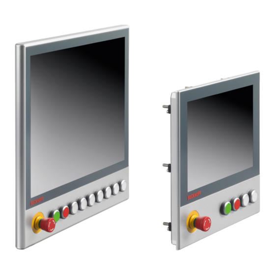
Product overview Product overview The C9900-G00x and C9900-G02x push button extensions can be used to control the central functions of a machine or system such as emergency stop, start or stop by means of electromechanical keys. The push button extensions are designed for the CP2xxx or CP39xx Control Panels and are already mounted ex factory. -
Page 10: Ordering Options
Product overview Ordering options You have different ordering options for the CP2xxx and CP39xx Control Panels. The options are adapted to the available display sizes of the control panels. 3.1.1 CP2xxx ordering options The following ordering options are available in combination with a CP2xxx built-in Control Panel: Table 2: CP2xxx ordering options Ordering option Description... - Page 11 Product overview C9900-G005 Push button extension for CP2x18 with horizontal 18.5-inch display • Push button extension below • 10 illuminated push buttons, type RAFI RAFIX 22FS+, round, 30 mm • 1 emergency stop button, type RAFI RAFIX 22FS+ • Labels for the push button caps allow each push button to be labeled individually •...
-
Page 12: Cp39Xx Ordering Options
Product overview 3.1.2 CP39xx ordering options The following ordering options are available in combination with a CP39xx mounting arm Control Panel: Table 3: CP39xx ordering options Ordering option Description C9900-G022 Push button extension for CP3912 with horizontal 12-inch display • Push button extension below •... - Page 13 Product overview C9900-G025 Push button extension for CP3918 with horizontal 18.5-inch display • Push button extension below • 10 illuminated push buttons, type RAFI RAFIX 22FS+, round, 30 mm • 1 emergency stop button, type RAFI RAFIX 22FS+ • Labels for the push button caps allow each push button to be labeled individually •...
-
Page 14: Description Of The Boards
Product overview Description of the boards NOTICE Material damage due to excessive switching voltage An excessively high switching voltage can lead to damage to property. • Supply the push buttons with a maximum of 24 V and a maximum switching capacity per push button of 250 mW. -
Page 15: Fig. 3 A919 3-Push Button Board
Product overview Table 4: Connection strip assignment - A918 emergency stop board Connection strip Terminal point Description Input normally closed contact 1 Output normally closed contact 1 Input normally closed contact 2 Output normally closed contact 2 Not used Not used A919 3-push button board Fig. 3: A919 3-push button board The 3-push button board A919 has two K-bus interfaces CON400 and CON 401 (Fig. -
Page 16: Fig. 4 A920 4-Push Button Board
Product overview Table 5: Assignment of connection strips 3-push button board A919 Connection strip Terminal point Description 24 V DC Input normally open contact 1 Output normally open contact 1 Input normally open contact 2 Output normally open contact 2 Input normally open contact 3 Output normally open contact 3 24 V output Digital input 1... -
Page 17: Direct Wiring
Product overview Table 6: Assignment of connection strips 4-push button board A920 Connection strip Terminal point Description 24 V DC Input normally open contact 1 Output normally open contact 1 Input normally open contact 2 Output normally open contact 2 Input normally open contact 3 Output normally open contact 3 Input normally open contact 4 Output normally open contact 4... -
Page 18: Fig. 6 A972 3-Push Button Board
Product overview Table 7: Connection strip assignment - A971 emergency stop board Connection strip Terminal point Description Input normally closed contact 1 Output normally closed contact 1 Input normally closed contact 2 Output normally closed contact 2 Input normally open contact 1 Input normally open contact 1 A972 3-push button board 8 7 6 5... -
Page 19: Fig. 7 A973 4-Push Button Board
Product overview A973 4-push button board Fig. 7: A973 4-push button board The 4-push button board A973 has two external connection strips CON600 and CON601 (Fig. 7, No. 1). They are used to supply power to the board. Use the connection strip CON602 (No. 4) to wire the LEDs 1-4 and the push buttons S1 and S2. -
Page 20: Board Combinations
Product overview Board combinations An emergency stop board is always used in each setup. In addition, the 3 or 4-push button boards are combined depending on the option number. The following table lists all board combinations. Table 10: Board combinations Control panel Option number Number of push Emergency Number 3-push... -
Page 21: Fig. 9 Circuit Diagram 3-Push Button Boards
Product overview Circuit diagram 3-push button boards C9900-A919 C9900-A972 Fig. 9: Circuit diagram 3-push button boards C9900-G00x and C9900-G02x Version: 2.0... -
Page 22: Fig. 10 Circuit Diagram 4-Push Button Boards
Product overview Circuit diagram 4-push button boards C9900-A920 C9900-A973 Fig. 10: Circuit diagram 4-push button boards Version: 2.0 C9900-G00x and C9900-G02x... -
Page 23: Cp Configurator
Product overview CP configurator If you order your control panel with a push button extension under the corresponding ordering option, this is standardized. Alternatively you have the possibility to make customer specific adjustments to the push button extension by means of the CP configurator. You can customize the arrangement, functionality, color, sequence and wiring type of the push buttons. -
Page 24: Fig. 13 Select Display Size
Product overview Fig. 13: Select display size 5. Open the drop-down menu Push button query. 6. Select the wiring type of the push buttons of your push button extension. If you hold the mouse over the fields without clicking, info texts about the wiring types appear (see also chapter 3.2 Description of the boards [} 14]). -
Page 25: Fig. 15 Select Push Button Type
Product overview Fig. 15: Select push button type 9. Click through the configuration of the push button until you reach the end. 10. When you have configured all the desired push buttons, click on Finalize configuration. Fig. 16: Completing the configuration 11. Enter your mail address and password or register if you do not have access data yet. C9900-G00x and C9900-G02x Version: 2.0... -
Page 26: Fig. 17 Log In/Register
Product overview Fig. 17: Log in/Register 12. Click Create option number. ð You will receive a confirmation email of your configuration with the corresponding generated option number. If you have already configured a push button extension and therefore have an associated generated option number, you can enter this in the configurator and plan further push button extensions based on the configuration. -
Page 27: Commissioning
5. Check the contents for visible shipping damage. 6. In case of discrepancies between the package contents and the order, or in case of transport damage, please inform Beckhoff Service (see Chapter 9 Service and Support [} 40]). C9900-G00x and C9900-G02x... -
Page 28: Access To Boards
Commissioning Access to boards Before you can wire the push button extensions, you must gain access to the boards. The procedures differ slightly according to the device. For the CP2xxx and CP39xx Control Panels with connection block, you only have to remove the cover for access. -
Page 29: Mounting Push Button Caps And Label
Commissioning Fig. 20: Access boards CP39xx mounting arm adapter Mounting push button caps and label You have the possibility to exchange the push button caps of your push button extension and thus change the color. In addition, you can individually label the push buttons by means of a transparent foil. The following ordering options are available to you: C9900-G00x and C9900-G02x Version: 2.0... -
Page 30: Table 11 Push Button Caps And Label
Commissioning Table 11: Push button caps and label Options Description C9900-Z255 Blue push button cap for individual application to a pushbutton extension C9900-G0xx, type Rafi FS+, diameter: 22.3 mm, 5 pcs C9900-Z256 Yellow push button cap for individual application to a push button extension C9900-G0xx, type Rafi FS+, diameter: 22.3 mm, 5 pcs C9900-Z257 Green push button cap for individual application to a push button extension C9900-G0xx,... -
Page 31: Fig. 21 Push Button Cap And Label
Commissioning STOP STOP Fig. 21: Push button cap and label C9900-G00x and C9900-G02x Version: 2.0... -
Page 32: Wiring
Commissioning Wiring CAUTION Risk of electric shock Dangerous touch voltages can lead to electric shock. To avoid electric shock, adhere to the following points: • Never connect or disconnect the device cables during a thunderstorm. • Provide protective earthing for handling the device. After you have gained access to the push button extension boards, you can wire the push button extension. -
Page 33: Fig. 23 Connecting Cables
Commissioning Fig. 23: Connecting cables You can lead the wiring out of the push button extension through an M20 gland. For a CP2xxx and a CP39xx with connection block, the M20 gland is located on the rear side of the panel at the push button extension (see Fig. -
Page 34: Fig. 25 M20 Gland Cp39Xx With Mounting Arm Adapter
Commissioning Fig. 25: M20 gland CP39xx with mounting arm adapter Version: 2.0 C9900-G00x and C9900-G02x... -
Page 35: Commissioning In The Twincat System Manager
Commissioning Commissioning in the TwinCAT System Manager With the help of the TwinCAT System Manager you can connect the push button extension. Proceed as follows: 1. Click on File > New > Project in the menu to create a new TwinCAT XAE project. 2. -
Page 36: Fig. 28 Select Device
Commissioning Fig. 28: Select device 5. Confirm the request Scan for boxes with Yes. Fig. 29: Scan boxes ð The selected device is inserted as a box in the tree view and displayed with the respective inputs and outputs (e.g. Term 2 to 5). 6. -
Page 37: Decommissioning
Decommissioning Decommissioning CAUTION Risk of electric shock Disconnecting the push button extension during a thunderstorm can cause electric shock. • Never disconnect the wiring during a thunderstorm. As part of the decommissioning of the push button extension, you must first gain access to the boards of the push button extension again. -
Page 38: Maintenance
Maintenance Maintenance Maintenance measures increase the efficiency of the device by ensuring long-term functionality. The cleaning of the push button extension contributes to this. Cleaning NOTICE Unsuitable cleaning agents The use of unsuitable cleaning agents can damage the device. • Clean the push button extension only as indicated. It is essential to observe the following aspects when cleaning the push button extension: •... -
Page 39: Technical Data
Technical data Technical data Table 12: Characteristics of the respective push button extensions Product designation C9900-G00x & C9900-G02x Shock resistance EN 60068-2-6: 10 to 58 Hz: 0.035 mm 58 to 500 Hz: 0.5 G (~ 5 m/s²) (sinusoidal vibration) Shock resistance (shock) EN 60068-2-27: 5 G (~50 m/s²), duration: 30 ms Supply voltage 24 V (20.4 –... -
Page 40: Appendix
33415 Verl Germany Phone: + 49 5246/963-0 email: info@beckhoff.de The addresses of the worldwide Beckhoff branches and agencies can be found on our website at http:// www.beckhoff.com/. You will also find further documentation for Beckhoff components there. Version: 2.0 C9900-G00x and C9900-G02x... -
Page 41: Approvals
Appendix Approvals The push button extension is CE and EAC certified. FCC approvals for the United States of America FCC: Federal Communications Commission Radio Frequency Interference Statement This device was tested and complies with the limits for a digital device of class A, according part 15 of the FCC regulations. - Page 42 List of figures List of figures Fig. 1 Structure with CP39xx........................Fig. 2 A918 emergency stop board ......................Fig. 3 A919 3-push button board......................Fig. 4 A920 4-push button board......................Fig. 5 A971 emergency stop board ......................Fig. 6 A972 3-push button board......................Fig.
- Page 43 List of tables List of tables Table 1 Legend structure .......................... Table 2 CP2xxx ordering options ......................Table 3 CP39xx ordering options......................Table 4 Connection strip assignment - A918 emergency stop board ............Table 5 Assignment of connection strips 3-push button board A919............Table 6 Assignment of connection strips 4-push button board A920............
- Page 45 More Information: www.beckhoff.com/en-en/products/ipc/control-panels/ accessories/ Beckhoff Automation GmbH & Co. KG Hülshorstweg 20 33415 Verl Germany Phone: +49 5246 9630 info@beckhoff.com www.beckhoff.com...
Need help?
Do you have a question about the C9900-G00 Series and is the answer not in the manual?
Questions and answers