
Related Manuals for Beckhoff EK1960 Series


Summary of Contents for Beckhoff EK1960 Series
- Page 1 Operating Instructions for EK1960 TwinSAFE Compact Controller Version: 1.3.1 Date: 2019-01-28...
-
Page 3: Table Of Contents
Description of safety symbols .................... 9 Documentation issue status ...................... 10 Version history of the TwinSAFE product .................. 11 2 System description TwinSAFE....................... 12 Extension of the Beckhoff I/O system with safety functions ............ 12 Safety concept .......................... 12 3 Product description.......................... 13 General description ......................... 13 Product designations ........................ 14... - Page 4 Table of contents 4.3.3 Creating a safety project in TwinCAT 3 ................ 43 4.3.4 Downloading the safety application ................. 75 Info data............................ 79 4.4.1 Info data for the connection .................... 79 4.4.2 Info data for function blocks..................... 80 4.4.3 Info data for the TwinSAFE group ................... 81 4.4.4 Info data for the device ....................
- Page 5 Table of contents 4.22 Maintenance .......................... 133 4.22.1 Cleaning......................... 133 4.23 Service life ............................. 134 4.23.1 Decommissioning ...................... 135 4.24 Firmware update of TwinSAFE products .................. 136 5 Appendix .............................. 139 Support and Service ........................ 139 Certificates............................. 140 EK1960 Version: 1.3.1...
- Page 6 Table of contents Version: 1.3.1 EK1960...
-
Page 7: Foreword
Product features Only the product features specified in the current user documentation are valid. Further information given on the product pages of the Beckhoff homepage, in emails or in other publications is not authoritative. Disclaimer The documentation has been prepared with care. The products described are subject to cyclical revision. For that reason the documentation is not in every case checked for consistency with performance data, standards or other characteristics. -
Page 8: Safety Instructions
Offenders will be held liable for the payment of damages. All rights reserved in the event of the grant of a patent, utility model or design. Delivery conditions In addition, the general delivery conditions of the company Beckhoff Automation GmbH & Co. KG apply. Safety instructions 1.2.1... -
Page 9: Description Of Safety Symbols
Foreword 1.2.3 Description of safety symbols In these operating instructions the following instructions are used. These instructions must be read carefully and followed without fail! DANGER Serious risk of injury! Failure to follow this safety instruction directly endangers the life and health of persons. WARNING Risk of injury! Failure to follow this safety instruction endangers the life and health of persons. -
Page 10: Documentation Issue Status
Foreword Documentation issue status Version Comment 1.3.1 • Layout corrected at chapter Sample program for parameterization 1.3.0 • Description of Module Fault Link active parameter added • Description of Multiple Download added • Description of input and output signals expanded •... -
Page 11: Version History Of The Twinsafe Product
Foreword Version history of the TwinSAFE product This version history lists the releases of the software and hardware versions. A description of the respective changes to the previous version is also listed. Updated hardware and software The TwinSAFE products are subject to a cyclical revision. We reserve the right to revise and change the TwinSAFE products at any time and without notice. -
Page 12: System Description Twinsafe
Extension of the Beckhoff I/O system with safety functions The TwinSAFE products from Beckhoff enable convenient expansion of the Beckhoff I/O system with safety components, and integration of all the cabling for the safety circuit within the existing fieldbus cable. Safe signals can be mixed with standard signals as required. -
Page 13: Product Description
Product description Product description General description EK1960 – TwinSAFE-Compact-Controller The EK1960 is a TwinSAFE controller with 20 fail-safe inputs and 24 fail-safe outputs. The EK1960-2600 and EK1960-2608 variants feature an additional four relays, each with one make contact. The EK1960 TwinSAFE compact controller is suitable for safety applications up to SIL 3 according to IEC 62061 and IEC 61508 and up to Cat. -
Page 14: Product Designations
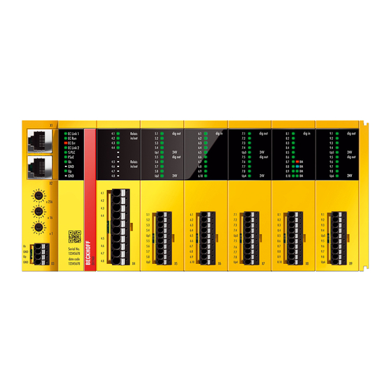
Product description Fig. 1: EK1960-260x TwinSAFE-Compact-Controller The EK1960 without relay option has a dummy cap on X4. Fig. 2: EK1960-000x TwinSAFE compact controller without relay option Product designations Product designation Description EK1960-0000 EK1960 with EtherCAT RJ45 connections – without relay option EK1960-0008 EK1960 with EtherCAT M8 connections –... -
Page 15: Inputs And Outputs Of The Ek1960
Product description Inputs and outputs of the EK1960 NOTE Fuses for the EK1960 Fuses must be provided for the power supplies of the EK1960 2 A each for U and U (X3) and 5 A each for to U (X5, X7, X9). plug contact Name... - Page 16 Product description plug contact Name Description Input (X6) Input 1 (Channel8.FSIN Module 1.Channel1.Input) Input 2 (Channel8.FSIN Module 1.Channel2.Input) Input 3 (Channel9.FSIN Module 2.Channel1.Input) Input 4 (Channel9.FSIN Module 2.Channel2.Input) Input 5 (Channel10.FSIN Module 3.Channel1.Input) Input 6 (Channel10.FSIN Module 3.Channel2.Input) Input 7 (Channel11.FSIN Module 4.Channel1.Input) Input 8 (Channel11.FSIN Module 4.Channel2.Input)
- Page 17 Product description plug contact Name Description Output (X9) Output 17 from U (Channel5.FSOUT Module 5.Channel1.Output) Output 18 from U (Channel5.FSOUT Module 5.Channel2.Output) Output 19 from U (Channel5.FSOUT Module 5.Channel3.Output) Output 20 from U (Channel5.FSOUT Module 5.Channel4.Output) Peripheral voltage U 24 V (SELV/PELV) P5 ...
-
Page 18: Connection Technology
Product description Connection technology 3.4.1 Power supply spring contact strip The power supply spring contact strip is required for the X3 connection. Item number ZS2003-0001 Number of contacts Contact spacing 3.5 mm Connection methods Spring-loaded terminal technology Wire cross-section (solid-wire) 0.2 –... -
Page 19: Intended Use
The TwinSAFE compact controller may only be used for the purposes described below! The TwinSAFE compact controller expands the application range of the Beckhoff EtherCAT system by functions that enable it to be used in the field of machine safety as well. The TwinSAFE compact controller is designed for machine safety functions and the directly associated industrial automation tasks. -
Page 20: Technical Data
Product description Technical data Product designation EK1960 Number of inputs Number of outputs 24 (+ 4 optional relay outputs) Cable length between sensor and input 30 m (if cables with a cross-sectional area of 0.75 mm² are used) Cable length between output and actuator 30 m (if cables with a cross-sectional area of 0.75 mm²... - Page 21 Product description Product designation EK1960 Climate category according to EN 60721-3-3 (the deviation from 3K3 is possible only with optimal environmental conditions and also applies only to the technical data which are specified differently in this documentation) Permissible level of contamination level of contamination 2 according to EN 60664-1 (comply with the chapter Cleaning [} 133])
-
Page 22: Technical Data - Relay Option
Product description 3.6.1 Technical data – relay option Product designation EK1960-260x Contacts 1 NO / 1 NC Make contact material (NO) AgNi + 0.2 µm Au Feedback contact material (NC) AgNi + 5 µm Au Coil voltage Maximum continuous current, NO contact DC13 (24 V ) I = 2 A (when used in safety applications) AC15 (230 V ) I = 3 A... -
Page 23: Fig. 4 Operating Lifetime Of The Agni No Contact For Dc1, Dc13, Ac1 And Ac15
Product description Operating lifetime for contact material AgNi Fig. 4: Operating lifetime of the AgNi NO contact for DC1, DC13, AC1 and AC15 Reduction factor for inductive loads Fig. 5: Reduction factor for inductive loads EK1960 Version: 1.3.1... -
Page 24: Safety Parameters
Product description Safety parameters In the following tables the safety parameters are shown separately for inputs, logic and outputs. The PFH values for the inputs, logic and outputs used must be added together for the complete safety loop. The Safety-over-EtherCAT communication is included in the logic part. General parameters EK1960 Lifetime [a]... - Page 25 Product description Relay output parameters (Cat. 2 – single-channel) Value 7.25 E-10 6.42 E-05 MTTF high high Performance Level PL d Category relay option values Characteristic numbers EK1960-260x value (DC13 24 V and I ≤ 2 A) 1,500,000 [switching cycles] value (AD15 230 V and I ≤ 1 A) 750,000 [switching cycles] value (AD15 230 V and I...
-
Page 26: Error Response Times
Product description Logic parameters Value 5.18 E-09 4.32 E-05 MTTF high high Performance Level PL e Category Output safety parameters The following table contains the safety parameters for the digital output of the EK1960. This must be added to the input and logic value to determine the total PFH value. Digital output parameters Value 1.5 E-10... -
Page 27: Characteristic Curve Of The Inputs
Product description Characteristic curve of the inputs The characteristic curve of the inputs of the EK1960 is similar to type 3 according to EN 61131-2. Fig. 6: EK1960 input characteristic curve 3.10 Test pulses for the outputs The output signals of each module of the EK1960 can be determined via the parameter Diag TestPulse Active. - Page 28 Product description Test Time until next test Channel 1 (only channel 1 is tested) Module switch (all four channels are tested) Channel 2 (only channel 2 is tested) Module switch (all four channels are tested) Channel 3 (only channel 3 is tested) Module switch (all four channels are tested) Channel 4 (only channel 4 is tested) Module switch (all four channels are tested)
-
Page 29: Load Characteristic Curve - Inductive Load
Product description 3.11 Load characteristic curve – inductive load If an external freewheeling diode is not used for inductive loads, the permissible maximum load can be taken from the following characteristic curve. Fig. 7: Characteristic curve - inductive load EK1960 Version: 1.3.1... -
Page 30: Block Diagram Of The Ek1960
Product description 3.12 Block diagram of the EK1960 The following block diagram shows the basic structure of the EK1960. The sub-modules shown exist several times according to the information on the sub-modules. Fig. 8: Block diagram EK1960 Version: 1.3.1 EK1960... -
Page 31: Address Setting Of The Twinsafe Compact Controller
Product description 3.13 Address setting of the TwinSAFE compact controller Fig. 9: Address selection switch of the EK1960 The TwinSAFE address of the controller must be set with the three rotary switches on the housing of the EK1960 TwinSAFE controller. TwinSAFE addresses between 1 and 4095 are available. Rotary switch Address 1 (top) -
Page 32: Dimensions
Product description 3.14 Dimensions Fig. 10: EK1960 dimensions Width: 230.5 mm Height: 100 mm Depth: 58.6 mm 3.15 Wiring examples 3.15.1 Inputs and outputs Examples of the wiring of the individual connections of the EK1960 are shown in the following. Power supply X3 The X3 connection is for the supply of power to the EK1960. The internal logic and the E-bus connection are supplied via U , while U supplies the relays and the safe inputs (safety mat operation mode). -
Page 33: Fig. 12 Relay Contact X4 (Ek1960-260X Only)
Product description Potential-free relay contacts C4 (EK1960-260x) The relay contacts (four relays each with one make contact) are fed out to the X4 connection. The area surrounded by the dotted line shows the make contacts of the individual relays. Fig. 12: Relay contact X4 (EK1960-260x only) Digital outputs X5, X7 and X9 Connection X5, X7 and X9 must be supplied with 24 V on contacts 5 and 10. -
Page 34: Fig. 14 Digital Inputs X6 And X8
Product description Digital inputs X6, X8 The digital inputs are supplied with 24V signals. In the default setting, static or clocked signals are supported. Safe outputs of the EK1960 can also be selected as the clock signal source. Fig. 14: Digital inputs X6 and X8 Version: 1.3.1 EK1960... -
Page 35: Fig. 15 Safety Mat Wiring
Product description Safety mat connection example Inputs 8.7 to 8.10 on connection X8 of the EK1960 can be configured for a safety mat operation mode. Only safety mats operating according to the resistance-change principle may be used. Only 8K2 (8.2 kΩ) termination resistors are supported. -
Page 36: Clocked Signals
Product description 3.15.2 Clocked signals All output groups (four outputs each) can be configured as clock outputs. The test pulses of the groups can be set accordingly via parameters. If a sensor such as a key switch (represented here by S19 and S20) is two-channel wired within one single non-metallic sheathed cable, the two channels must be fed from different clock sources. -
Page 37: Operation
Operation Operation Environmental conditions Please ensure that the TwinSAFE components are only transported, stored and operated under the specified conditions (see technical data)! WARNING Risk of injury! The TwinSAFE components must not be used under the following operating conditions. • under the influence of ionizing radiation (that exceeds the level of the natural environmental radiation) •... -
Page 38: Fig. 17 Installation Position And Minimum Distances
Operation 4.2.3.2 Control cabinet / terminal box For operation, the TwinSAFE compact controller must be installed in a control cabinet or terminal box with IP54 protection class according to IEC 60529 as a minimum. 4.2.3.3 Installation position and minimum distances For the prescribed installation position the mounting rail is installed horizontally and the mating surfaces of the TwinSAFE compact controller point towards the front (see illustration below). -
Page 39: Fig. 18 Mounting The Ek1960 On The Din Rail
Operation Fig. 18: Mounting the EK1960 on the DIN rail The EK1960 is released from the DIN rail by opening the two clamps on top of or underneath the device. To do this, insert a screwdriver into the recess provided and open the clamp until it latches. Fig. 19: DIN rail clamp closed Once the two upper or lower clamps are unlocked, the device can be taken off the DIN rail in an upward or downward direction. -
Page 40: Electrical Installation
Operation 4.2.4 Electrical installation 4.2.4.1 Overvoltage protection If protection against overvoltage is necessary in your system, provide an overvoltage protective circuit (surge filter) for the power supply to the TwinSAFE compact controller. 4.2.4.2 Wiring The connectors support the push-in wiring of individual wires and fine-wire conductors with wire-end sleeves. In the case of multi-wire and fine-wire conductors, the latch must be depressed to connect the conductor with the contact point. -
Page 41: Fig. 22 Cable Routing
Operation 4.2.4.3 Signal cables Cable routing Fig. 22: Cable routing NOTE Route the signal cable separately The signal cable must be routed separately from potential sources of interference, such as motor supply ca- bles, 230 V power cables etc.! Interference caused by cables routed in parallel can influence the signal form of the test pulses and thus cause diagnostic messages (e.g. -
Page 42: Configuration Of The Controller In Twincat
The EK1960 cannot be used under TwinCAT 2 4.3.2 Insertion of a controller An EK1960 is inserted in exactly the same way as any other Beckhoff EtherCAT device. In the list, open Safety Terminals and select the EK1960. Fig. 23: Inserting an EK1960 Version: 1.3.1... -
Page 43: Creating A Safety Project In Twincat 3
4.3.3 Creating a safety project in TwinCAT 3 Further documentation Information regarding the TwinSAFE-blocks, -groups and -connections can be found in the Twin- SAFE-Logik-FB Documentation available on the Beckhoff website under http://www.beckhoff.de/german/download/twinsafe.htm. 4.3.3.1 Add new item In TwinCAT 3 a new project can be created via Add New Item… in the context menu of the Safety node. -
Page 44: Fig. 26 Twincat Safety Project Wizard
Operation 4.3.3.2 TwinCAT Safety Project Wizard In the TwinCAT Safety Project wizard you can then select the target system, the programming language, the author and the internal project name. Select the setting Hardware Safety PLC as the target system and the graphical editor as the programming language. The author and the internal project name can be freely selected by the user. -
Page 45: Fig. 28 Linking Of Target System And Twinsafe Compact Controller
Operation Fig. 28: Linking of target system and TwinSAFE compact controller 4.3.3.4 Alias devices The communication between the safety logic and the I/O level is realized via an alias level. At this alias level (subnode Alias Devices) corresponding alias devices are created for all safe inputs and outputs, and also for standard signal types. -
Page 46: Fig. 30 Selection From The I/O Tree
Operation Fig. 30: Selection from the I/O tree The alias devices are created in the safety project when the dialog is closed via OK. Alternatively, the user can create the alias devices individually. To this end select Add and New item from the context menu, followed by the required device. -
Page 47: Fig. 32 Alias Device In The Safety Project Structure
Operation 4.3.3.5 Parameterization of the alias device The settings can be opened by double-clicking on the Alias Device in the safety project structure. Fig. 32: Alias Device in the safety project structure The Linking tab contains the FSoE address, the checkbox for setting as External Device and the link to the physical I/O device. -
Page 48: Fig. 35 Selecting An Alias Device
Operation Parameter Description User inter- action re- quired Conn. no. Connection number - automatically assigned by the TwinCAT system Conn ID Connection ID: preallocated by the system, but can be changed by the user. A Check Conn ID must be unique within a configuration. Duplicate connection IDs result in an error message. -
Page 49: Fig. 36 Safety Parameter For The Device
Operation Fig. 36: Safety parameter for the device 4.3.3.6 Connection to AX5805/AX5806 There are separate dialogs for linking an AX5805 or AX5806 TwinSAFE Drive option card, which can be used to set the safety functions of the AX5000 safety drive options. Creating and opening of an alias device for an AX5805 results in five tabs;... -
Page 50: Fig. 38 Ax5000 Safety Drive Options - General Ax5805 Settings
Operation Fig. 38: AX5000 safety drive options - general AX5805 settings The Process Image tab can be used to set the different safety functions for the AX5805. Fig. 39: AX5000 safety drive options - Process Image The parameters under the General AX5805 Settings and Process Image tabs are identical to the parameters under the Safety Parameters tab. -
Page 51: Fig. 40 Ax5000 Safety Drive Options - Function Diagram
Operation Fig. 40: AX5000 safety drive options - Function Diagram 4.3.3.7 External connection An external Custom FSoE Connection can be created for a connection to a further EL69x0, EJ6910, KL6904 or third-party device. If a dedicated ESI file exists for a third-party device, the device is listed as a selectable safety device, and the Custom FSoE Connection option is not required. -
Page 52: Fig. 41 Creating An External Connection (Custom Fsoe Connection)
Operation Fig. 41: Creating an external connection (Custom FSoE Connection) Before the connection can be used and linked further, the process image size must be parameterized. This can be set under the Process Image tab. Suitable data types for different numbers of safety data are provided in the dropdown lists for the input and output parameters. -
Page 53: Fig. 43 Renaming The Individual Signals Within The Telegram
Operation Fig. 43: Renaming the individual signals within the telegram The connection is linked under the Linking tab. The Link button next to Full Name (input) and Full Name (output) can be used to select the corresponding variable. Fig. 44: Selecting the variables This can be a PLC variable, for example, which is then forwarded to the remote device or can be linked directly with the process image of an EtherCAT Terminal (e.g. - Page 54 Operation Fig. 45: Direct linking with the process image of an EtherCAT Terminal Further information can be found in the TwinCAT documentation for the variable selection dialog. The Connection tab is used to set the connection-specific parameters. Fig. 46: Connection-specific parameters Version: 1.3.1 EK1960...
- Page 55 Operation Detailed information about the individual settings can be found in the following table. Parameter Description User inter- action re- quired Conn. no. Connection number: is automatically assigned by the TwinCAT system Conn ID Connection ID: preallocated by the system, but can be changed by the user. A Check Conn ID must be unique within a configuration.
- Page 56 Operation Fig. 48: Switching the alias device to Local Only the info data for inputs and outputs can be activated on the Connection tab. Fig. 49: Info data for local connection The corresponding parameters are set for each input and output module on the Safety Parameter tab. Version: 1.3.1 EK1960...
- Page 57 Operation Fig. 50: Safety parameters of the output and input modules Overview of output parameters PrmName Index Meaning Value FSOUT Module 0 8000:00 Settings for output module 0 (outputs 01 - 04) Settings Common ModuloDiag 8000:01 Test frequency of the clocking TestPulse All modules used are processed in succession in one logic cycle respectively.
- Page 58 Operation Fig. 51: Safety parameters of the input modules Version: 1.3.1 EK1960...
- Page 59 Operation Overview of input parameters PrmName Index Meaning Value FSIN Module 9 80F0:00 Settings for input module 9 (inputs 17 - 18) This setting Settings Common exists only for modules 9 and 10 InputMode 80F0:03 Only input modules 9 and 10 support the parameters - Digital Mode On Digital Mode On and Bumper Mode On.
- Page 60 Operation Fig. 52: Process data of input modules 9 and 10 The input modules 9 and 10 have a fault evaluation per channel when using the Bumper Mode, so there are also 2 separate ModuleFault signals. When using the digital mode, both signals are set in the case of a module fault.
- Page 61 Operation Fig. 53: Function blocks available for EL6910/EJ6910 The function blocks can be moved from the toolbox into the SAL worksheet via drag and drop. Variables can be created by clicking next to a function block input or output, which can then be linked with alias devices in the Variable Mapping dialog.
- Page 62 Operation Once the pointer connector has been selected from the toolbox, connections between the input and output ports of the function blocks can be dragged with the mouse. Fig. 55: Dragging a connection between two function blocks Version: 1.3.1 EK1960...
- Page 63 Operation Fig. 56: Connection between two function blocks 4.3.3.10 Networks For structuring the safety application, several networks can be created within a sal worksheet. Right-click in the worksheet and select Add After and Network or Add Before and Network to create a network after or before the current network.
- Page 64 Operation Alternatively, Change Link can be selected by opening the context menus next to the FB port. Fig. 58: Change Link This function opens a dialog for selecting a suitable FB port. Fig. 59: Dialog for selecting a suitable FB port Once the link has been created on one side of the connection, the link is automatically set/displayed on the opposite side.
- Page 65 Operation 4.3.3.11 TwinSAFE groups It makes sense to create TwinSAFE groups in cases where different machine safety zones are to realize, or simply in order to separate the fault behavior. Within a group, a FB or connection error (here: alias device) leads to a group error and therefore to switching off all outputs for this group.
- Page 66 Operation Fig. 63: Change Link This function opens a dialog for selecting a suitable FB port. Fig. 64: Dialog for selecting a suitable FB port Once the link has been created on one side of the connection, the link is automatically set/displayed on the opposite side.
- Page 67 Operation Fig. 65: Link display 4.3.3.12 Variables of the TwinSAFE group The inputs and outputs of the TwinSAFE groups are consolidated under the Group Ports tab of the Variable Mapping dialog. Group inputs EL6910/EJ6910 For a project to be valid, as a minimum the signals Run/Stop and ErrAck must be linked. Fig. 66: The Variable Mapping dialog EK1960 Version: 1.3.1...
- Page 68 Operation Group Port Direction Description Err Ack Error Acknowledge for resetting errors within the group - Signal must be linked with a standard variable Run/Stop 1 - Run; 0 – Stop - Signal must be linked with a standard variable Module Input for an error output of another module that is connected, e.g.
- Page 69 Operation 4.3.3.13 Order of the TwinSAFE groups The order of the groups can be changed, in order to realize a defined processing sequence of the safety application. To this end, select the entry Edit TwinSAFE Group Order via the node menu of the safety project node. A dialog opens, in which the order of the groups can be changed.
- Page 70 Operation Fig. 69: The command line below the SAL worksheet Currently the commands listed in the following table are supported. Command Description FBNAME FB_INSTANCENAME NETWORKNAME; Adding a function block Sample: safeAnd FBAnd1 Network1 FB_INSTANCENAME->PORTNAME = Creating a variable mapping VARIABLE_NAME; Sample: FBAnd1->AndIn1 = testVariable FB_INSTANCENAME->PORTNAME = Creating a connection between two FBs FB_INSTANCENAME->PORTNAME;...
- Page 71 Operation Channel Interface Description Both Deactivated Both inputs are deactivated Single-Channel 1 Activated Channel 1: Single-channel evaluation Channel 2: deactivated Single-Channel 2 Activated Channel 1: deactivated Channel 2: Single-channel evaluation Single-Channel Both Activated Channel 1: Single-channel evaluation Channel 2: Single-channel evaluation Two-Channel Both inputs are activated, and two-channel evaluation with Discrepancy Time (ms)
- Page 72 Operation Fig. 72: Menu Change Inport Settings Fig. 73: Dialog Change InPort Settings 4.3.3.16 Variable Mapping Fig. 74: Variable Mapping Version: 1.3.1 EK1960...
- Page 73 Operation Variables are linked to the alias devices in the Variable Mapping window. Use the Link button to open the selection dialog for the alias port. Safe only signal types or safe and standard signal types are offered in the selection dialog, depending on the port setting of the FB. Safe Boolean signals are shown with a yellow background, standard signal types with a white background.
- Page 74 Operation Toolbar TwinCAT Safety Icon Name Description Verify Safety Project The safety project is checked for validity. Verify Complete Safety The safety project including the hardware level is checked for validity. Project Download Safety Project Loading the safety project onto the target system, here EL6910/ EJ6910 Delete Safety Project Deleting the safety project from the target system, here EL6910/...
-
Page 75: Downloading The Safety Application
Operation Fig. 78: Check Safe Addresses context menu Fig. 79: Check Safe Addresses dialog 4.3.4 Downloading the safety application Before downloading the safety project to the EL6910/EJ6910 or a logic component, the project should first be checked for validity. If the hardware is complete, the hardware level can be used for checking, or checking can take place at the project level , if online access is only available for the EL6910/EJ6910 or... - Page 76 Operation NOTE Power supply during download Make sure that the TwinSAFE Logic is not switched off during the download. This can lead to unexpected behavior or permanently disable the TwinSAFE Logic. WARNING Execution of the safety application During a login or download of a safety application, the execution of the current project is stopped on the TwinSAFE Logic.
- Page 77 Operation Fig. 82: Download Project Data – The Download Result dialog Once the download is complete, the download results are displayed. Use the Next button to move to the next dialog. Fig. 83: Download Project Data – The Final Verification dialog The locally calculated CRCs and the online CRCs of the safety project are displayed in the Final Verification dialog.
- Page 78 Operation Fig. 84: Download Project Data – The Activation dialog In the Activation dialog the user re-enters the password to activate the safety project on the EL6910/EJ6910 or the logic component. Use the Finish button to complete the download of the safety project. WARNING Verification of the input and output process data After downloading the safety-related program to the TwinSAFE logic, the user must check that the input...
-
Page 79: Info Data
Operation Info data 4.4.1 Info data for the connection Info data for connections can be enabled on the Connection tab of the alias device. Fig. 85: Enabling the info data for connections The info data are shown in the I/O tree structure below the EL6910 in the process image. From here, these signals can be linked with PLC variables. -
Page 80: Info Data For Function Blocks
Operation Fig. 88: Info data for the connection in the I/O tree structure as individual data 4.4.2 Info data for function blocks For function blocks, info data can be enabled in the properties of the function block. Fig. 89: Enabling the info data for function blocks The info data are shown in the I/O tree structure below the EL6910 in the process image. -
Page 81: Info Data For The Twinsafe Group
Operation Fig. 90: Info data for the function block in the I/O tree structure 4.4.3 Info data for the TwinSAFE group For TwinSAFE groups, info data can be enabled via the properties of the TwinSAFE group. Fig. 91: Enabling the info data in the properties of the TwinSAFE group The info data are shown in the I/O tree structure below the I/O device in the process image. -
Page 82: Info Data For The Device
Operation Fig. 92: Info data for the TwinSAFE group in the tree structure 4.4.4 Info data for the device The info data for the EK1960 can be activated on theTarget System tab. These are the serial number of the EK 1960 and the current online-CRC of the safety project. Fig. 93: Activation of the info data for the EK1960 The info data are shown in the I/O tree structure below the EK1960 in the process image. -
Page 83: Version History
Operation Fig. 94: Info data in the EK1960 tree structure Info data of the internal EK1960 inputs and outputs In addition to the project CRC and the serial number, the local inputs and outputs of the EK1960 connection are shown under Device Info Data. The inputs, outputs, module errors and module ErrAck signals are shown below the entry Internal I/O. -
Page 84: User Administration
Operation User Administration User administration is called up via the Target System tree item. Use Get User List to read the current list of users of the EL6910, EJ6910 or EK1960. The user Administrator cannot be deleted. The default password can and should be replaced with a customer-specific password. - Page 85 Operation Fig. 99: User Administration - Add New User(s) - User Credentials Fig. 100: User Administration - Add New User(s) - Access Rights Enter the new user and the corresponding password (twice). The password must be at least 6 characters long. In addition, select the rights for the new user. Use the button to apply these data and display them in the New User list.
-
Page 86: Backup/Restore
Operation Fig. 101: User Administration - New User added Several users can be created before leaving the dialog via the Finish button. Access Rights Description Change Password Users can change their password. Download Safe Logic Data The user can load the safety-related program onto the EL6910, EJ6910 or EK1960. - Page 87 EL6910, EJ6910 or EK1960 has changed, or start the restore manually via a service menu, e.g. in the visualization. Detailed information about the Backup/Restore mechanism is available from Beckhoff Support. Restore If a project that doesn't match the system is loaded during a restore, this will only be detected when the distributed CRCs are checked.
- Page 88 The PLC function blocks with which a backup and restore to a TwinSAFE logic component (currently EL6910, EJ6910 or EK1960) can be carried out are available through Beckhoff Support. This is a compiled library that can be installed in the TwinCAT Library Repository.
- Page 89 Operation Fig. 104: FB_SAVELOGICPROGRAM illustration Fig. 105: FB_SAVELOGICPROGRAM parameters FB_RESTORELOGICPROGRAM Fig. 106: FB_RESTORELOGICPROGRAM illustration Fig. 107: FB_RESTORELOGICPROGRAM parameters Sample PROGRAM MAIN fb_save: FB_SAVELOGICPROGRAM; fb_restore: FB_RESTORELOGICPROGRAM; StartBackup: BOOL; EL6910AmsNetID AT %I*: ARRAY [0..5] OF BYTE; EL6910port AT %I*: WORD; internalBuffer: array[0..16#FFFF] of byte; FileString: T_MaxString := 'c:\temp\safety\complibTest_EL6910.bin'; LocalAmsNetID: T_AmsNetID := '172.55.76.53.1.1'; SaveDone: BOOL;...
-
Page 90: Export/Import Of The Safety Project
Operation RestoreResult: STRING(200); RestoreErr: BOOL; END_VAR // Backup of the TwinSAFE logic program fb_save( bExecute:= StartBackup, au8EcatNetId:= EL6910AmsNetID, u16EcatPort:= EL6910port, u32BufferAddress:= ADR(internalBuffer), u32BufferSize:= SIZEOF(internalBuffer), sFileName:= FileString, sNetIDWriteFile:= LocalAmsNetID, Done=> SaveDone, sResult=> SaveResult, bErr=> SaveErr); // Restore of the TwinSAFE logic program fb_restore( bExecute:= StartRestore, au8EcatNetId:= EL6910AmsNetID, u16EcatPort:= EL6910port, u32BufferAddress:= ADR(internalbuffer2), u32BufferSize:= SIZEOF(internalBuffer2), sFileName:= FileString, sNetIDReadFile:= LocalAmsNetID, Done=> RestoreDone, sResult=> RestoreResult, bErr=> RestoreErr);... - Page 91 Operation Fig. 109: Saving the safety project in a binary format (e.g. for the TwinSAFE loader) A previously exported safety project can be imported via the context menu of the main Safety entry in the TwinCAT project structure. Add Existing Item… can be used to select the file type for the import. Fig. 110: Selecting the file type for importing a safety project The following file types are supported: •...
-
Page 92: Diag History Tab
Operation Fig. 111: Importing a safety project Diag History tab Any errors that occur in the EL6910, EJ6910 or EK1960 are stored in the their diag history. The diag history can be viewed by selecting the EL6910, EJ6910 or EK1960 in the I/O tree structure and then selecting the Diag History tab. -
Page 93: Twinsafe Sc Configuration
Operation Fig. 113: Diag History - Advanced Settings Advanced Settings Setting Description Message Types • disable Info Messages with status Info are not stored in the diag history • disable Warnings Messages with status Warning are not stored in the diag history •... - Page 94 Operation Fig. 114: Adding the TwinSAFE SC process data under the component, e.g. EL5021-0090 Additional process data with the ID TSC Inputs, TSC Outputs are generated (TSC - TwinSAFE Single Channel). Fig. 115: TwinSAFE SC component process data, example EL5021-0090 A TwinSAFE SC connection is added by adding an alias devices in the safety project and selecting TSC (TwinSAFE Single Channel) Fig. 116: Adding a TwinSAFE SC connection After opening the alias device by double-clicking, select the Link button...
- Page 95 Operation Fig. 117: Creating a link to TwinSAFE SC terminal The CRC to be used can be selected or a free CRC can be entered under the Connection tab of the alias device. Entry Mode Used CRCs TwinSAFE SC CRC 1 master 0x17B0F TwinSAFE SC CRC 2 master 0x1571F...
- Page 96 Operation Fig. 119: Selecting the process data size and the process data The process data (defined in the ESI file) can be adjusted to user requirements by selecting the Edit button in the dialog Configure I/O element(s). Fig. 120: Selection of the process data The safety address together with the CRC must be entered on the TwinSAFE SC slave side.
-
Page 97: Customizing / Disabling Twinsafe Groups
Operation Object „TSC Settings” Depending on the terminal, the index designation of the configuration object „TSC Settings“ can vary. Example: - EL3214-0090 and EL3314-0090, „TSC Settings“, Index 8040 - EL5021-0090, „TSC Settings“, Index 8010 - EL6224-0090, „TSC Settings“, Index 800F Fig. 122: Entering the safety address and the CRC TwinSAFE SC connections If several TwinSAFE SC connections are used within a configuration, a different CRC must be se-... - Page 98 Operation The customization can also be carried out during the download of the safety application. In order to be able to perform a customization, the groups must be set accordingly. This is done via the group properties. Fig. 123: Properties of the TwinSAFE group If one of the Customizing parameters (Passification Allowed, Permanent Deactivation Allowed or Temporary Deactivation Allowed) is set to TRUE, all outputs of the TwinSAFE group that are not Safety Alias Devices are listed in the list of Replacement Values.
- Page 99 Operation Fig. 125: Login The Customizing dialog opens once the user has entered the data and selected Next. The current group status is indicated with a green background. Fig. 126: Customizing TwinSAFE Groups The user can select the new status via the option area. In the sample below Deactivate Temporarily is selected.
-
Page 100: Saving The Analog Group Inputs Persistently
Operation TwinSAFE Logic in PreOP state If Customizing is carried out on a TwinSAFE Logic with EtherCAT status PreOP, the customizing of a group does not become active. Customizing must be carried out again if the TwinSAFE Logic is in the EtherCAT status SafeOP or OP. -
Page 101: New Features In Tc3.1 Build 4022
Operation 4.13 New features in TC3.1 Build 4022 In the TwinCAT Version 3.1 Build 4022 some extensions have been implemented for the TwinSAFE editor. With the release of the TwinCAT version, these are available to the user. This chapter lists the new features. 4.13.1 Group status The status of the TwinSAFE group is displayed as a color-coded frame in online mode. - Page 102 Operation Fig. 131: Group Status Online ERROR Fig. 132: Group Status Online STOP Version: 1.3.1 EK1960...
-
Page 103: Online View Group Ports
Operation 4.13.2 Online view group ports In online mode the group inputs and outputs are marked according to their signal status. A logical 1 of the signal is represented with a green background, a logical 0 with a white background. Error information is displayed with a red background. -
Page 104: Subfolder Alias Devices
Operation Fig. 135: Collapsing networks 4.13.5 Subfolder Alias Devices Under the node Alias Devices, further subfolders can be created. After the subfolder has been created, it can be renamed, here for example to Drives. Fig. 136: Adding a subfolder After adding a subfolder, Alias Devices can be added in this folder. Version: 1.3.1 EK1960... -
Page 105: Goto Linked Element
Operation Fig. 137: Subfolder e.g. Drives 4.13.6 Goto linked element The entry Goto Linked Element can be called via the context menu. All links and variables used on that port are listed. Selecting an entry triggers a jump to the corresponding position in the network, a TwinSAFE group or variable mapping. -
Page 106: Multiline Comments
Operation Fig. 139: Path view for safety Alias Devices For the Standard Alias Devices, the path to the signal below the TwinSAFE logic (full name), the link to the PLC (Linked to), and the name in the process image of the TwinSAFE logic are displayed. Fig. 140: Path view for Standard Alias Devices 4.13.8 Multiline comments... -
Page 107: Names Of Alias Devices In The Process Image
Operation 4.13.9 Names of Alias Devices in the process image The user has now the option of adapting the naming of process data below the TwinSAFE logic in the I/O tree. For this purpose, checkboxes are available on the Target System dialog to accept the naming of TwinSAFE connections and standard inputs and outputs from the respective Alias Device names. -
Page 108: 4.13.10 Project Settings - Verification
Operation 4.13.10 Project settings - Verification The project settings can be found below the target system. Safe Address Verification The Safe Address Verification entry is used to set how the safety addresses are checked. • Project wide unique (recommended) - Unique safety addresses within the entire solution •... -
Page 109: 4.13.12 Copy And Paste For Fbs And Comments
Operation Fig. 147: Project Properties - Diagnostic Diagnostic Properties of the group node If the group node of the TwinSAFE project is selected, the properties under the entry Diagnostic display the current TwinSAFE group parameters. These are e.g. the number of connections, the number of function blocks, or the number of standard signals. - Page 110 Operation Fig. 149: Copying the data After inserting the data, the following message appears. The user may have to adjust copied variable names. Fig. 150: Message box after inserting the data Version: 1.3.1 EK1960...
-
Page 111: 4.13.13 Global Settings In Visual Studio
Operation Fig. 151: Inserted data Here, in the example, the user must adapt the links of the output EStopOut and change the variable names Restart, Input_01, Input_02 and EDM so that no duplicate names are assigned. 4.13.13 Global settings in Visual Studio Options can be selected under the Tools menu in Visual Studio. - Page 112 Operation Under TwinCAT / TwinSAFE Environment / Default Info Data you can configure which info data should be activated automatically when TwinSAFE projects, groups, connections or FBs are created. Fig. 153: Global setting - Default Info Data Under TwinCAT / TwinSAFE Environment / Group Diagram Editor you can specify whether the Undo / Redo function should automatically zoom and scroll into the area that has changed.
-
Page 113: 4.13.14 Sorting
Operation 4.13.14 Sorting Setting the execution order of the groups via dialog The context menu of the project node can be used to access the execution order of the TwinSAFE groups. Fig. 155: Context menu - Edit TwinSAFE Group Order By selecting a group and then holding and dragging an entry with the mouse, the execution order of the groups can be changed. - Page 114 Operation Fig. 157: Sorting of Alias Devices Sorting of FBs (execution order) The execution order of the function blocks can be accessed via the context menu within the graphical worksheet. Fig. 158: Context Menu - Change Execution Order of FBs By selecting an FB and then holding and dragging an entry with the mouse, the execution order of the function blocks can be changed.
-
Page 115: 4.13.15 Direct Mapping Of Local I/Os
Operation Fig. 159: Execution order FBs 4.13.15 Direct mapping of local I/Os If a TwinSAFE Logic has local inputs and outputs, e.g. an EK1960, an assignment to safe and non-safe signals can be made by the user via the Internal Direct Mapping tab of the alias device. These direct assignments have the advantage that no logic program has to be created by the user for this purpose. -
Page 116: 4.13.16 Backup/Restore Settings
Operation 4.13.16 Backup/Restore settings Backup/restore settings have been extended so that TwinSAFE logic components can also be used to store a TwinSAFE project CRC. The following table describes the settings for each TwinSAFE connection listed in the Backup/Restore dialog. Checkbox Desciption Available in Store Project CRC in Slave... -
Page 117: 4.13.17 Multiple Download
Operation Fig. 161: Backup/Restore settings 4.13.17 Multiple download New TwinSAFE products typically also support the use of a local logic function. Thus the number of necessary downloads can increase significantly. In TwinCAT 3.1 Build 4022 it is now also possible to load several safety projects simultaneously onto the corresponding logic components via the Multiple Download feature. - Page 118 Operation Fig. 163: Multiple Download - Selection of projects In the general settings, enter the user name and password and check the displayed serial numbers of the logic components. Use the Verified checkbox to confirm that the correct serial numbers are displayed and used.
- Page 119 Operation Fig. 165: Multiple Download - Final Verification To activate the safety projects, enter the password for the current user again and confirm with the Next button. Fig. 166: Multiple Download - Activation The Result dialog lists all safety projects with the status Activated and Downloaded. Click the Finish button to finish the multiple download.
-
Page 120: Diagnostics
Operation Fig. 167: Multiple Download - Result 4.14 Diagnostics 4.14.1 Diagnostic LEDs Fig. 168: Diagnostic LED Version: 1.3.1 EK1960... - Page 121 Operation LED EC Link1 (green) State Meaning EC Link 1 No connection on the incoming EtherCAT segment upstream EtherCAT device or EtherCAT Master connected flashes communication with upstream EtherCAT device or EtherCAT Master LED EC RUN (green) Display Meaning permanently off EtherCAT State INIT (Initialisation) flashing uniformly EtherCAT State PREOP (Pre- Operational)
-
Page 122: Status Leds
Operation LED Up The U LED lights up as soon as the 24 V voltage is present at the U connection. 4.14.2 Status LEDs Relais LEDs Digital inputs Version: 1.3.1 EK1960... -
Page 123: Diagnostic Objects
Operation Digital outputs Inputs 17 - 20 LED left green - Digital Mode On LED right blue - Bumper Mode On 4.14.3 Diagnostic objects CAUTION Do not change CoE objects! Do not make any modifications to the CoE objects in the TwinSAFE components! Any modifications (e.g. using TwinCAT) of the CoE objects will permanently set the TwinSAFE components to the Fail-Stop state. -
Page 124: Cycle Time Of The Safety Project
Operation Index F985 : Device Info Data C2 CoE object F985 currently displays internal temperature and voltage values for the TwinSAFE component. Index Name Meaning Flags Default F985:01 Voltage C1 Voltage µC1 F985:02 Temperature C2 Temperature µC2 F985:03 Firmware CRC C2 CRC of the firmware on µC2 F985:04 Vendor data CRC C2 CRC of the vendor data on µC2... -
Page 125: Diagnosis History
Operation Index FEA0 : CTRL Diag Data Index Name Description Flags Default FEA0:09 Actual Safety Control Current execution time of the EK1960, when Task Execution Time Logic State = 1 (RUN) Cycle time = 1.25 * value (Mean value over 64 cycles) FEA0:0A Min Safety Control Task Minimum execution time of the EK1960, when Execution Time... - Page 126 Operation Index 10F3 Diagnosis History Index (hex) Name Meaning Data type Flags Default 10F3:0 Diagnosis History 10F3:01 Maximum Maximum number of stored messages. A UINT8 0x40 (64 Messages maximum of 64 messages can be stored. After that the respective oldest messages are overwritten.
- Page 127 Operation Dynamic parameters in the diagnostic messages Type Data type Description Flags parameter 1 UINT16 Describes the type of parameter 1 Bits 12 to 15 = Bits 0 to 11 = data type of parameter 1 0x0001 - BOOLEAN 0x0002 - INT8 0x0003 - INT16 0x0004 - INT32 0x0005 - UINT8...
-
Page 128: Project Design Limits Of The Ek1960
Operation 4.15 Project design limits of the EK1960 Project design limits The maximum project design size of the EK1960 is limited by the available memory. This is man- aged dynamically. The values specified in the following table are therefore only guide values and may differ from the actual values, depending on the safety project. -
Page 129: Sync-Manager Configuration
Operation 4.17 Sync-Manager Configuration Depending on the size of the TwinSAFE project on the TwinSAFE logic, it may be necessary to adjust the sync manager configuration. As soon as the following message appears during the saving or downloading of the project, the sync manager configuration for the device has to be adapted. - Page 130 Operation Fig. 174: Sync Manager settings Fig. 175: Setting the start address for SM3 After changing the start address, all dialogs are closed with OK, the TwinCAT project is saved and the configuration is activated. If the calculation was carried out correctly, no error message should now be displayed and the project should be executed without errors.
-
Page 131: Reaction Times Of Local Signals
Operation 4.18 Reaction times of local signals Typical reaction time of the local input and output The typical reaction time is the time that is required to transmit information from the sensor to the actuator, if the overall system is working without error in normal operation. Fig. 176: Reaction time of local signals Definition Description... - Page 132 Operation Definition Description RTSensor Reaction time of the sensor until the signal is provided at the interface. Typically supplied by the sensor manufacturer. RTInput Reaction time of the safe input, such as EL1904 or EP1908. This time can be found in the technical data.
-
Page 133: Reaction Times Bumper Mode
Operation 4.20 Reaction times Bumper mode If the operating mode BumperMode is set for inputs 8.7 to 8.10, safety mats or safety bumpers can be evaluated at these inputs. The connection diagram can be found under Inputs and outputs [} 32]. In this operation mode, the inputs give out a pulsed voltage. -
Page 134: Service Life
Operation 4.23 Service life The TwinSAFE compact controllers have a service life of 20 years. Due to the high diagnostic coverage within the lifecycle no special proof tests are required. The TwinSAFE controllers carry a data code, which is composed as follows: Date Code: CW YY SW HW Legend Example: Datecode 08160201... -
Page 135: Decommissioning
Operation 4.23.1 Decommissioning DANGER Serious risk of injury! Bring the bus system and the TwinSAFE compact controller into a safe, de-energized state before starting with the disassembly of the TwinSAFE compact controller! Disposal In order to dispose of the device, it must be removed and fully dismantled. •... -
Page 136: Firmware Update Of Twinsafe Products
TwinSAFE component is deleted and replaced by a new version. The latest firmware can be downloaded from the Beckhoff website or requested from Beckhoff Support. The versions are available in an encrypted form and can only be loaded onto the matching TwinSAFE product. - Page 137 Operation Performing the firmware update Click the button (1) in the TwinCAT system to enter Config mode. Confirm the query with OK (2). After that a further window appears which must be confirmed with Yes (Ja) (3). Deactivate the "Free Run" with No (Nein) (4).
- Page 138 Operation Fig. 182: Firmware update of TwinSAFE products - Part 2 In the place where you have stored the desired firmware version, select the firmware file (9) and click "Open" (10). Confirm the window that then opens with "OK" (11); the firmware update is then performed. After successful completion you must click OK (12) in the concluding "Function Succeeded"...
-
Page 139: Appendix
Beckhoff's branch offices and representatives Please contact your Beckhoff branch office or representative for local support and service on Beckhoff products! The addresses of Beckhoff's branch offices and representatives round the world can be found on her internet pages: http://www.beckhoff.com You will also find further documentation for Beckhoff components there. -
Page 140: Certificates
Appendix Certificates Version: 1.3.1 EK1960... - Page 141 List of figures List of figures Fig. 1 EK1960-260x TwinSAFE-Compact-Controller................Fig. 2 EK1960-000x TwinSAFE compact controller without relay option..........Fig. 3 Load limit curve, make contact ....................Fig. 4 Operating lifetime of the AgNi NO contact for DC1, DC13, AC1 and AC15 ........ Fig.
- Page 142 List of figures Fig. 45 Direct linking with the process image of an EtherCAT Terminal..........Fig. 46 Connection-specific parameters ....................Fig. 47 Insertion of an EK1960 alias device .................... Fig. 48 Switching the alias device to Local ....................Fig. 49 Info data for local connection.......................
- Page 143 List of figures Fig. 91 Enabling the info data in the properties of the TwinSAFE group ..........Fig. 92 Info data for the TwinSAFE group in the tree structure ............... Fig. 93 Activation of the info data for the EK1960 ................... Fig.
- Page 144 List of figures Fig. 137 Subfolder e.g. Drives ........................105 Fig. 138 Goto Linked Element ........................105 Fig. 139 Path view for safety Alias Devices....................106 Fig. 140 Path view for Standard Alias Devices..................106 Fig. 141 Multiline comments ........................106 Fig.
- Page 145 List of figures Fig. 182 Firmware update of TwinSAFE products - Part 2 ................ 138 Fig. 183 Firmware update of TwinSAFE products - Part 3 ................ 138 EK1960 Version: 1.3.1...
Need help?
Do you have a question about the EK1960 Series and is the answer not in the manual?
Questions and answers