Beckhoff BC8050 Documentation

Beckhoff BC8050 Documentation

Bus terminal controller with rs485 or rs232 interface
Table of Contents

Advertisement

Documentation
BC8050 und BC8150
Bus Terminal Controller with RS485 or RS232 Interface
Version:
Date:
3.0.0
2017-07-18

Advertisement

Table of Contents
loading

Summary of Contents for Beckhoff BC8050

  • Page 1 Documentation BC8050 und BC8150 Bus Terminal Controller with RS485 or RS232 Interface Version: 3.0.0 Date: 2017-07-18...
  • Page 3: Table Of Contents

    Safety instructions ..........................  6 Documentation issue status...................... 7 2 Product overview............................ 8 BCxx50 Overview ...........................  8 The principle of the Bus Terminal .................... 9 The Beckhoff Bus Terminal system .................... 9 Technical data .......................... 11 2.4.1 Technical Data - BCxx50 .................... 11 2.4.2 Technical data - RS485 .................... 13...
  • Page 4 Switching between controllers ......................  82 Example programs for serial communication................ 84 Firmware Update ..........................  85 General operating conditions...................... 87 Test standards for device testing.................... 90 Bibliography .......................... 90 List of Abbreviations ........................ 90 Support and Service ........................ 91 Version: 3.0.0 BC8050 und BC8150...
  • Page 5: Foreword

    The TwinCAT Technology is covered, including but not limited to the following patent applications and patents: EP0851348, US6167425 with corresponding applications or registrations in various other countries. ® EtherCAT is registered trademark and patented technology, licensed by Beckhoff Automation GmbH, Germany Copyright © Beckhoff Automation GmbH & Co. KG, Germany.
  • Page 6: Safety Instructions

    All the components are supplied in particular hardware and software configurations appropriate for the application. Modifications to hardware or software configurations other than those described in the documentation are not permitted, and nullify the liability of Beckhoff Automation GmbH & Co. KG. Personnel qualification This description is only intended for trained specialists in control, automation and drive engineering who are familiar with the applicable national standards.
  • Page 7: Documentation Issue Status
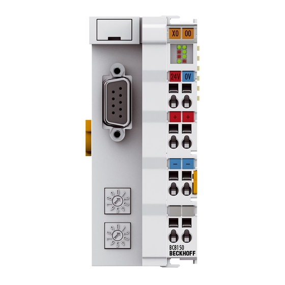
    Foreword Documentation issue status Version Comment 3.0.0 • Migration 2.0.0 • BC8050 added 1.1.1 • ADS communication example added [} 84] 1.1.0 • Notes to meet the UL requirements added. 1.0.1 • Minor routine corrections 1.0.0 • First public issue (only available in German)
  • Page 8: Product Overview

    The BCxx50 devices are programmed according to the powerful IEC 61131-3 standard. Like for all other BECKHOFF controllers, the TwinCAT automation software is the basis for parameterization and programming. Users therefore have the familiar TwinCAT tools available, e.g. PLC programming interface, System Manager and TwinCAT Scope.
  • Page 9: The Principle Of The Bus Terminal

    The principle of the Bus Terminal Fig. 1: The principle of the Bus Terminal The Beckhoff Bus Terminal system Up to 256 Bus Terminals, with 1 to 16 I/O channels per signal form The Bus Terminal system is the universal interface between a fieldbus system and the sensor / actuator level.
  • Page 10 Bus Couplers for all usual bus systems The Beckhoff Bus Terminal system unites the advantages of a bus system with the possibilities of the compact series terminal. Bus Terminals can be driven within all the usual bus systems, thus reducing the controller parts count.
  • Page 11: Technical Data

    - Serial ADS - ModbusRTU - KS8000 protocol - ModbusASCII - ModbusRTU - ModbusASCII Interfaces Serial interface COM1 (RS232 for configuration and programming, automatic baud rate detection 9600/19200/38400 baud) Terminal Bus (K-Bus) 64 (255 with K-bus extension) BC8050 und BC8150 Version: 3.0.0...
  • Page 12 Permissible ambient -40°C ... +85°C temperature range during storage Relative humidity 95 % no condensation Vibration / shock resistance conforms to EN 60068-2-6 / EN 60068-2-27 EMC immunity / emission conforms to EN 61000-6-2 / EN 61000-6-4 Installation position variable Protection class IP20 Version: 3.0.0 BC8050 und BC8150...
  • Page 13: Technical Data - Rs485

    2 x 0.25 mm², cable type A according to EN 50 170 Segment length up to 1200 m Data transfer rate 1200 - 38400 baud Topology RS485 line Transmission time depending on protocol and baud rate )* only via the configuration interfaces, not via RS485. BC8050 und BC8150 Version: 3.0.0...
  • Page 14: Technical Data - Rs232

    Data transfer medium shielded copper cable, 3 x 0.25 mm² Segment length up to 15 m Data transfer rate 1200 - 38400 baud Topology RS232 peer to peer Transmission time depending on protocol and baud rate Version: 3.0.0 BC8050 und BC8150...
  • Page 15: Technical Data - Plc

    32 kbyte Remanent flags 2 kbyte PLC cycle time Approx. 3.0 ms for 1000 IL commands (without I/O cycle) Programming languages IEC 6-1131-3 (IL, LD, FBD, ST, SFC) Runtime 1 SPS Task Online Change Up/Down Load Code Yes/Yes BC8050 und BC8150 Version: 3.0.0...
  • Page 16: Mounting And Wiring

    3.1.1 Dimensions The Beckhoff Bus Terminal system is characterized by low physical volume and high modularity. When planning a project it must be assumed that at least one Bus Coupler and a number of Bus Terminals will be used. The mechanical dimensions of the Bus Couplers are independent of the fieldbus system.
  • Page 17: Installation

    The spring-loaded terminal is opened with a screwdriver or rod, by exerting gentle pressure in the opening above the terminal. The wire can be inserted into the terminal without any force. The terminal closes automatically when the pressure is released, holding the wire safely and permanently. BC8050 und BC8150 Version: 3.0.0...
  • Page 18: Wiring

    3.2.1 Potential groups, insulation testing and PE Potential groups A Beckhoff Bus Terminal block usually has three different potential groups: • The fieldbus interface is electrically isolated (except for individual Low Cost couplers) and forms the first potential group. • Bus Coupler / Bus Terminal Controller logic, K-bus and terminal logic form a second electrically isolated potential group.
  • Page 19: Power Supply

    The connection is made by means of the upper spring-loaded terminals labelled 24 V and 0 V. This supply voltage is used for the electronic components of the Bus Coupler / Bus Terminal Controllers and (via the K- bus) the electronic components of the Bus Terminals. It is galvanically separated from the field level voltage. BC8050 und BC8150 Version: 3.0.0...
  • Page 20: Fig. 9 Terminal Points For The Bus Terminal Controller Supply

    The current load from the power contact must not exceed 10 A for long periods. The current carrying capacity between two spring-loaded terminals is identical to that of the connecting wires. Version: 3.0.0 BC8050 und BC8150...
  • Page 21: Programming Cable

    Do not interrupt the ground connection for the supply voltage When the programming cable (between BCxx50 and PC) is connected, the ground connec- tion of the Bus Terminal controller must not be interrupted or disconnected, since this may Attention destroy the programming cable. BC8050 und BC8150 Version: 3.0.0...
  • Page 22: Rs232 Connection

    Pin assignment of the RS232 D-Sub socket Fig. 12: RS232 pin assignment Cable The cable must be crossed type. GND is connected 1:1. Only use assigned and described pins. Fig. 13: Three-core cable with shield, crossed Version: 3.0.0 BC8050 und BC8150...
  • Page 23: Rs485 Connection

    A two-core cable with shielding should be used. The shielding should be connected to signal ground (GND). Pin assignment of the RS485 D-sub socket Fig. 14: RS485 pin assignment Cable The BC8050 can establish connections to several devices; the maximum permitted cable length is 1200 m. Fig. 15: Two-core cable with shield BC8050 und BC8150 Version: 3.0.0...
  • Page 24: Parameterization And Commissioning

    The I/O LEDs flash when the Bus Terminal Controller starts up. If the system is in an error-free state, the I/O LEDs should stop flashing after approx. 2-3 seconds. In the event of a fault the error type determines which LED flashes (see chapter Diagnostic LEDs). Fig. 16: Start-up behavior of the Bus Terminal Controller Version: 3.0.0 BC8050 und BC8150...
  • Page 25: Setting The Address

    (as long as the coupler is switched off), only the end terminal may be connected (KL9010), and the coupler must then be connected to the supply voltage. Address 99: Factory setting Address 98: Delete boot project Address 97: Delete TwinCAT configuration BC8050 und BC8150 Version: 3.0.0...
  • Page 26: Baud Rate

    The following is required for the TwinCAT configuration (TC file): • Via the fieldbus (PROFIBUS, CANopen, Ethernet) PROFIBUS: (BC3150, BX3100) ◦ PC with FC310x from version 2.0 and TwinCAT 2.9 build 1000 ◦ BX3100 with CIF60 or CP5412 Version: 3.0.0 BC8050 und BC8150...
  • Page 27 9. Open the TC file in the System Manager, complete the configuration and transfer it to the BCxx50, BCxx20 or BXxx00 10. Transfer the program to BCxx50, BCxx20 or BXxx00 11. Creating a boot project BC8050 und BC8150 Version: 3.0.0...
  • Page 28: Creating A Twincat Configuration

    The TwinCAT configuration is loaded into the Bus Terminal Controller via ADS protocol. Serial ADS protocol (all Bus Terminal Controllers of the BXxx00 and BCxx50 series) Enter the serial ADS connection, as described in the chapter Serial ADS [} 34]. Version: 3.0.0 BC8050 und BC8150...
  • Page 29: Fig. 20 Downloading A Twincat Configuration

    Select the corresponding Bus Terminal Controller. Fig. 21: Selecting the Bus Terminal Controller The state of the Bus Terminal Controller is shown at the bottom right of the System Manager. Fig. 22: State of the Bus Terminal Controller BC8050 und BC8150 Version: 3.0.0...
  • Page 30: Uploading A Twincat Configuration

    (e.g. fieldbus card) and the Bus Terminal Controller. Choose Target System Select the Bus Terminal Controller onto which the configuration is to be loaded. Use the function key [F8] to open the dialog for downloading your file to the corresponding device. Version: 3.0.0 BC8050 und BC8150...
  • Page 31: Fig. 24 Choose Target System

    The state of the Bus Terminal Controller is shown at the bottom right of the System Manager. Fig. 26: State of the Bus Terminal Controller Click on the red folder. The TwinCAT configuration will now be uploaded. BC8050 und BC8150 Version: 3.0.0...
  • Page 32: Resources In The Bus Terminal Controller

    The percentages are added here. In the example from Fig. Memory for code mapping, 8% of the memory is allocated to the mapping calculation. Fig. 28: Memory for code mapping Data memory mapping Data memory for mapping. The values are to be considered individually, i.e. each value can be up to 100%. Version: 3.0.0 BC8050 und BC8150...
  • Page 33: Fig. 29 Data Memory Mapping

    Fig. Other Memory (2) "Used Huge Heap" is required for the ADS communication. % values. This value should be less than 30 %. Fig. Other Memory (3) "Used File Area" is required for the TwinCAT configuration, the TSM file and the 16 kbyte flash access. % values. BC8050 und BC8150 Version: 3.0.0...
  • Page 34: Ads Connection Via Serial Interface

    Initializing the ADS connection Enter the Bus Terminal Controller in the remote connection under TwinCAT. Click on the TwinCAT icon and open the features menu. The following settings can be made under the >AMS Remote< tab. Version: 3.0.0 BC8050 und BC8150...
  • Page 35: Fig. 32 Properties Of The Remote Connection

    Manager. In this case a new serial ADS connection is only possible, if the AMS Net ID is adjusted. BX series: reading the AMS Net ID The current AMS Net ID can be read from the menu via the display of BX series Bus Terminal Controller. AMS Net ID 1.1.1.1.1.1 BC8050 und BC8150 Version: 3.0.0...
  • Page 36: Rs232 Interface

    Watchdog setting - at 0 ms the watchdog is disabled, adjustable up to 64000 ms max. The baud rate and parity are only valid if the address switch is set to 40-59. The input and output sizes are calculated from the attached variables. Version: 3.0.0 BC8050 und BC8150...
  • Page 37: Fig. 35 "Communication Properties" Tab

    Fig. 36: Creating variables (inputs, outputs) Please not that an even start address (0, 2, 4, 6, ...) has to be selected for variables with a size of 2 bytes or greater. Fig. 37: Definition of variables BC8050 und BC8150 Version: 3.0.0...
  • Page 38: K-Bus

    If breakpoints are set in PLC Control, the K-Bus is no longer processed, i.e. the outputs are set to a safe state (zero). K-Bus Sync Mode Writing and reading of the Bus Terminals can take place synchronously with task 1 or the fieldbus. Version: 3.0.0 BC8050 und BC8150...
  • Page 39: Fig. 39 Bx Diag Tab

    Factory Settings: the Bus Terminal Controller is set to its delivery. These settings are reactivated via Restart System or by switching the system off and on again (display shows DEFAULT-CONFIG). Reset Maximum Values: resets the maximum values BC8050 und BC8150 Version: 3.0.0...
  • Page 40: Configuration Software Ks2000

    • The BX controller must be in FreeRun mode. Activate it with the TwinCAT System Manager. You can now log in with the KS2000 configuration software via ADS (port 100) or the serial cable and use the KS2000 dialogs in the Bus Terminals. Version: 3.0.0 BC8050 und BC8150...
  • Page 41: Programming

    Limited by memory TwinCAT PLC The Beckhoff TwinCAT Software System turns any compatible PC into a real-time controller with a multi-PLC system, NC axis control, programming environment and operating station. The TwinCAT programming environment is also used for programming the BC/BX. If you have TwinCAT PLC (Windows NT4/2000/XP) installed, you can use the fieldbus connection or the serial port for downloading and debugging software.
  • Page 42: Twincat Plc - Error Codes

    If libraries are integrated this value may be insufficient. In this case, the number of POUs should be increased. To this end, open in PLC Control under Projects/Options... Fig. 41: Menu path Projects / Options / Controller Settings ...the controller settings. Version: 3.0.0 BC8050 und BC8150...
  • Page 43: Fig. 42 Controller Settings

    2 x 16 kbyte of data are available by default. If large data quantities are to be used, this range should be increased. A maximum of 14 data segments are possible for the BX. Fig. 44: Menu path Projects / Options / Build BC8050 und BC8150 Version: 3.0.0...
  • Page 44 Programming Fig. 45: Build Version: 3.0.0 BC8050 und BC8150...
  • Page 45: Remanent Data

    A program sample can be found below. Function block test (no program code required - in ST semicolon is sufficient) FUNCTION_BLOCK Test VAR_INPUT END_VAR VAR_OUTPUT END_VAR END_VAR VAR_IN_OUT      Counter   :INT; END_VAR MAIN program PROGRAM MAIN     fb_Test:Test; END_VAR VAR RETAIN     iCounter1:INT; END_VAR fb_Test(Counter:=iCounter1); BC8050 und BC8150 Version: 3.0.0...
  • Page 46: Allocated Flags

    . The fieldbus data length depends on the fieldbus system used. Inputs Outputs Bus Terminal %IB0 ... Bus Terminal %QB0 ... Fieldbus data (PLC variables) %IB1000 ... Fieldbus data (PLC variables) %QB1000 ..  %IB2047 maximal ...  %QB2047 maximal Version: 3.0.0 BC8050 und BC8150...
  • Page 47 Position 9: 1 x KL9010 Process image Bus Terminal Position Input image Output image KL1501 %IB0...%IB5 %QB0...%QB5 KL3002 %IB6...%IB13 %QB6...%QB13 KL4002 %IB14...%IB21 %QB14...%QB21 KL6001 %IB22...%IB29 %QB22...%QB29 KL1012 %IX30.0..30.1 KL1104 %IX30.1..30.5 KL2012 %QX30.0..30.1 KL2034 %QX30.2..30.5 KL9010 BC8050 und BC8150 Version: 3.0.0...
  • Page 48: Mapping The Bus Terminals

    Mapping the Bus Terminals The precise assignment of the byte-oriented Bus Terminals may be found in the configuration guide for the particular bus terminal. This documentation is available on the Beckhoff Products & Solutions CD or on the Internet under http://www.beckhoff.de. Byte oriented Bus Terminals...
  • Page 49: Local Process Image In The Twincat Configuration

    Bus Terminal, as required. This is parameterized in the System Manager, and the configuration is then downloaded to the Bus Terminal Controller (see TwinCAT configuration [} 26]). It is also possible to upload an existing TwinCAT configuration. BC8050 und BC8150 Version: 3.0.0...
  • Page 50: Creating A Boot Project

    1 byte. Boolean expressions should always be masked in a byte or word. Example 1: A structure on the BX/BCxx50 and on the PC Variable BX/BCxx50 memory PC memory (TwinCAT) Byte %..B0 %..B0 INT (1) %..B2 %..B1 INT (2) %..B4 %..B3 Version: 3.0.0 BC8050 und BC8150...
  • Page 51 Larger fieldbus data blocks You can transfer larger fieldbus data blocks, in order to have a reserve for your structure. Disadvantage: These reserves are then transferred with each fieldbus telegram, resulting in Note overload of the fieldbus communication. BC8050 und BC8150 Version: 3.0.0...
  • Page 52: Up- And Downloading Of Programs

    Fig. 48: Opening the options menu Select Source Download. Fig. 49: Selecting Source Download Here you can set which parts of the source code are to be downloaded to the Bus Terminal Controller, and when. Version: 3.0.0 BC8050 und BC8150...
  • Page 53 Under Online/Source code download the program code can now be transferred to the Bus Terminal Controller. Fig. 50: Downloading the program code After a short delay, a window will open that indicates the download progress. Fig. 51: Download progress BC8050 und BC8150 Version: 3.0.0...
  • Page 54 • BCxx50 or BX via serial, if you are connected to the Bus Terminal Controller via the serial interface. Fig. 53: Selecting the data transfer route Then select the device and confirm with OK. Fig. 54: Selecting the device Version: 3.0.0 BC8050 und BC8150...
  • Page 55: Libraries

    Libraries overview The TwinCAT Automation Software offers various libraries for the BCxx50 series Bus Terminal Controllers (Bus Coupler with PLC functionality) (see BECKHOFF Information System). Download The libraries are also included in this documentation. To extract the libraries, left-click on the link and copy the libraries to directory TwinCAT\PLC\LIB.
  • Page 56: Seriell_Set Data Structure

    BC8150. It is therefore possible to set the length of the I/O data, the baud rate, and the transfer mode from the local PLC project. The function block is not required for the TwinCAT configuration, as in this case the settings are created via the System Manager. Version: 3.0.0 BC8050 und BC8150...
  • Page 57 • BC8150 library (https://infosys.beckhoff.com/content/1033/bc8x50/Resources/ lbx/4059878411.lbx) (old version) • BC8150 library (https://infosys.beckhoff.com/content/1033/bc8x50/Resources/ lbx/4059880587.lbx) (current version) • example for BC8150 and KS8000 protocol (https://infosys.beckhoff.com/content/1033/bc8x50/ Resources/prx/4059882763.prx) • example for BC8150 and ModbusRTU protocol (https://infosys.beckhoff.com/content/1033/ bc8x50/Resources/prx/4059884939.prx) BC8150_Settings Fig. 55: Function block BC8150_SETTINGS FUNCTION_BLOCK BC8150_Settings VAR_INPUT bWriteSet       :BOOL;...
  • Page 58: Tcbasebcxx50

    [} 58]. The structure definition can be found in the system library. The index in this field is the task ID. Development environment Target platform PLC libraries to be linked TwinCAT v2.9.0 BCxx50, BC9x20 Controller TcBaseBCxx50.lbx 5.12.3.2 System Task Info Type TYPE SYSTEMTASKINFOTYPE STRUCT     active             :       BOOL;     taskName           :       STRING(16);     firstCycle         :       BOOL;     cycleTimeExceeded  :       BOOL;     cycleTime          :       UDINT;     lastExecTime       :       UDINT;     priority           :       BYTE;     cycleCount         :       UDINT; END_STRUCT END_TYPE Version: 3.0.0 BC8050 und BC8150...
  • Page 59 BCxx50, BC9x20 Controller TcBaseBCxx50.lbx 5.12.3.5 5.12.3.5.1 Local ADS Port Numbers Port number Description Reading and writing of registers and tables from the coupler and the complex Bus 100 [} 60] Terminals Local PLC process image 801 [} 60] BC8050 und BC8150 Version: 3.0.0...
  • Page 60 When reading the register, the time out of the ADS block has to be set to a time longer than 1 second. Note Setting the password When writing to the registers, the password has to be set (see the documentation for the particular Bus Terminal). Note Version: 3.0.0 BC8050 und BC8150...
  • Page 61: Program Transfer

    The Bus Terminal Controller can be programmed via the PC's RS232 interface. Before you can work with the Bus Terminal Controller, TwinCAT must be notified of it (see serial ADS [} 34]). Select the ADS connection in TwinCAT PLC Control. BC8050 und BC8150 Version: 3.0.0...
  • Page 62: Process Image

    The data of the KS8000 slave interface are stored in the allocated section of the BC8x50. The input data from the master perspective are stored in the controller output section from address %QB1000 (address offset 0 from the master perspective). Version: 3.0.0 BC8050 und BC8150...
  • Page 63 The output data from the master perspective are stored in the controller input section from address %IB1000 (address offset 0 from the master perspective). The maximum data length is 512 bytes input and 512 bytes output. BC8050 und BC8150 Version: 3.0.0...
  • Page 64: Rs232 - Interface

    2 bytes 2 bytes n Bytes 2 bytes 2 bytes 0x0D, 0x0A 6.1.1.2 Data Frame Description ModbusRTU (address 40-59) DEFAULT ModbusASCII (address 1-39) DEFAULT Data bits Stop bits Baud rate 9600 baud 38400 baud (automatic detection) Parity none even Version: 3.0.0 BC8050 und BC8150...
  • Page 65 Registers in the complex terminals and Bus Terminal Controller registers can be both read and written using the 2 byte PLC interface. The complex terminal registers are described in the associated terminal documentation. The Bus Coupler registers can be used, for example, to read terminal bus diagnostics data, BC8050 und BC8150 Version: 3.0.0...
  • Page 66 The inputs have offsets 0 - 0xFF while the outputs have offsets 0x800 - 0x8FF. The first two analog outputs are read in this example. The analog outputs begin at offset 0x800 (hex). The length indicates the number of channels to be read. Version: 3.0.0 BC8050 und BC8150...
  • Page 67 0xFF "FF" 0x46, 0x46 Data 2 high byte 0x00 "00" 0x30, 0x30 Data 2 low byte 0x00 "00" 0x30, 0x30 Error check, LRC/ 0xC6, 0xC1 "B0" 0x42, 0x30 End - frame t1-t2-t3 CRLF 0x0D, 0x0A BC8050 und BC8150 Version: 3.0.0...
  • Page 68 0x38 "38" 0x33, 0x38 Data 2 high byte 0x3F "3F" 0x33, 0x46 Data 2 low byte 0x0B "0B" 0x30, 0x42 Error check, LRC/ 0x80, 0x7E "6A" 0x36, 0x41 End - frame t1-t2-t3 CRLF 0x0D, 0x0A Version: 3.0.0 BC8050 und BC8150...
  • Page 69 0x30, 0x36 Start address low 0x00 "00" 0x30, 0x30 Data high 0x3F "3F" 0x33, 0x46 Data low 0xFF "FF" 0x46, 0x46 Error check, LRC/ 0xDA, 0xB0 "A9" 0x41, 0x39 End - frame t1-t2-t3 CRLF 0x0D, 0x0A BC8050 und BC8150 Version: 3.0.0...
  • Page 70 Response with subfunction 1 Before the Bus Terminal Controller restarts, it sends a response with subfunction 1. Note Subfunctions 0 and 1 The BC8150 has subfunctions 0 and 1 implemented. All other subfunctions return "0". Note Version: 3.0.0 BC8050 und BC8150...
  • Page 71 00 0F 00 00 Counter value Number of error responses (subfunction 16) Contains the number of error answers that the slave has sent. Subfunction Data field (query) Data field (response) 00 10 00 00 Counter value BC8050 und BC8150 Version: 3.0.0...
  • Page 72 0x30, 0x38 Start address low 0x00 "00" 0x30, 0x30 Length high 0x00 "00" 0x30, 0x30 Length low 0x02 "02" 0x30, 0x32 Error check, LRC/ 0x43, 0x02 "DB" 0x44, 0x42 End - frame t1-t2-t3 CRLF 0x0D, 0x0A Version: 3.0.0 BC8050 und BC8150...
  • Page 73 Data 1 low 0x38 "38" 0x33, 0x38 Data 2 high 0x3F "3F" 0x33, 0x46 Data 2 low 0x0B "0B" 0x30, 0x42 Error check, LRC/CRC 0xF8, 0xA7 "E3" 0x45, 0x33 End - frame t1-t2-t3 CRLF 0x0D, 0x0A BC8050 und BC8150 Version: 3.0.0...
  • Page 74: Protocol Overview

    (free running mode). The KS2000 configuration software can be used to switch the mode to synchronous. In synchronous mode, access by the Bus Coupler/Fieldbus Box to the Bus Terminals/ extension modules is synchronous with access by the controller to the Bus Coupler/Fieldbus Box. Version: 3.0.0 BC8050 und BC8150...
  • Page 75 The checksum is formed by adding up the contents of the individual bytes (total request string, without checksum byte). Any overflow is not taken into account. Response The Bus Coupler/Fieldbus Box responds to a request by the master. BC8050 und BC8150 Version: 3.0.0...
  • Page 76 The process data inputs are entered as data words in Intel format. Checksum The checksum is formed by adding up the contents of the individual bytes (total request string, without checksum byte). Any overflow is not taken into account. Version: 3.0.0 BC8050 und BC8150...
  • Page 77: Introduction To The System

    KS8000 Communication Software Fig. 60: Communication library icon The Beckhoff KS8000 Communication Library provides functions with which it is possible to communicate with the serial Bus Couplers (BK8000, BK8100, IP/ILxxxx-B8x0) easily via a serial PC interface. The KS8000 can be used as an OCX with all programming languages that use the Component Object Model (COM) specifications from Microsoft (VC++, Visual Basic from version 4.0, Delphi, Java, etc).
  • Page 78: Topology Of The Physical Rs232 Structure

    RS232 - Interface 6.2.2 Topology of the physical RS232 structure RS232 is a peer-to-peer connection. The means that only two devices can be connected at any time. The maximum cable length is 15 meters. Version: 3.0.0 BC8050 und BC8150...
  • Page 79: Error Handling And Diagnosis

    K-Bus is re-triggered NOTE Reading K-bus state by ADS In default or TwinCAT configuration the fieldbus state can be read via ADSREAD. Parameter ADSREAD function block Description NetID local – empty string Port IndexGroup 16#0006 IndexOffset 16#000C_9000 BC8050 und BC8150 Version: 3.0.0...
  • Page 80: Diagnostic Leds

    LEDs for K-Bus diagnostics LED (Power LEDs) Meaning LED RUN LED off: no K-Bus update, LED on, flashing: K-bus running LED ERR LED off: no error, LED flashing: see K-Bus error code Version: 3.0.0 BC8050 und BC8150...
  • Page 81 LED WD not implemented LED RX Flashes when data are being received LED TX Flashes when data are being sent LED PLC - PLC diagnostics Meaning PLC LED LED on: PLC running, LED off: PLC stopped BC8050 und BC8150 Version: 3.0.0...
  • Page 82: Appendix

    A maximum of one task is available. This task must be configured. PLC and fieldbus terminals For the standard Bus Terminal Controllers (BCxx00) it was possible to select whether a Bus Terminal is assigned to the fieldbus or the local PLC. Version: 3.0.0 BC8050 und BC8150...
  • Page 83 In the Bus Terminal controllers of the BCxx50/BCxx20 and BXxx00 series, libraries have the extension *.lbx, programs have the extension *.prx. Allocated variables For the Bus Terminal controllers of the BCxx50/BCxx20 and BXxx00 series, a limited number of allocated data are available: • Inputs 2 kB, %IB0..2048 BC8050 und BC8150 Version: 3.0.0...
  • Page 84: Example Programs For Serial Communication

    The serial interface of the BC8150 can also be used as a Modbus slave. In this example, a panel from the company Beijers is connected. Further information about the panel can be found at www.beijerelectronics.de. Fig. 63: Connection example BC8150 to a CIMREX 12 panel from Beijers Version: 3.0.0 BC8050 und BC8150...
  • Page 85: Firmware Update

    41 on the BC8150. After 10-20 seconds a numerical value should start incrementing on the panel and stop when F2 is pressed on the Cimrex 12. sample program in ST for BC8150 (any terminal configuration) (https://infosys.beckhoff.com/ content/1033/bc8x50/Resources/prx/4059893643.prx) Example Cimrex 12 panel (https://infosys.beckhoff.com/content/1033/bc8x50/Resources/ zip/4059895819.zip)
  • Page 86 Note for BX3100: Updates are not available with BX3100 firmware 0.64 (or lower). If these devices need updating, send the BX3100 to the manufacturer with a corresponding note. Beckhoff Automation GmbH & Co. KG Service Department Stahlstr. 31 33415 Verl, Germany Firmware update program 241 (https://infosys.beckhoff.com/content/1033/bc8x50/Resources/...
  • Page 87: General Operating Conditions

    BX's display. After successful download (approx. 2 to 3 minutes) the Bus Terminal Controller reboots automatically. Fig. 68: Status messages relating to the firmware update General operating conditions The following conditions must be met in order to ensure flawless operation of the fieldbus components. BC8050 und BC8150 Version: 3.0.0...
  • Page 88 Protection against water no protection Component identification Every supplied component includes an adhesive label providing information about the product's approvals. For sample, on the BK2000 Bus Coupler: The following information is printed on the label: Version: 3.0.0 BC8050 und BC8150...
  • Page 89 (Use a 4 A fuse or a Class 2 power supply to meet UL requirements) Data transfer rate 2.5 Mbaud Manufacturer Beckhoff Automation GmbH & Co. KG CE mark Conformity mark UL mark Mark for UL approval. UL stands for the Underwriters Laboratories Inc., the leading certification organization for North America, based in the USA.
  • Page 90: Test Standards For Device Testing

    Appendix Test standards for device testing EMC immunity EN 61000-6-2 Electromagnetic emission EN 61000-6-4 Vibration / shock resistance Vibration resistance EN 60068-2-6 Shock resistance EN 60068-2-27 Bibliography in preparation List of Abbreviations in preparation Version: 3.0.0 BC8050 und BC8150...
  • Page 91: Support And Service

    Beckhoff's branch offices and representatives Please contact your Beckhoff branch office or representative for local support and service on Beckhoff products! The addresses of Beckhoff's branch offices and representatives round the world can be found on her internet pages: http://www.beckhoff.com You will also find further documentation for Beckhoff components there.
  • Page 92 Maximum number of POUs exceeded..................Fig. 41 Menu path Projects / Options / Controller Settings..............Fig. 42 Controller settings........................Fig. 43 Global memory insufficient ......................Fig. 44 Menu path Projects / Options / Build ................... Version: 3.0.0 BC8050 und BC8150...
  • Page 93 Selecting a BX series Bus Terminal Controller................Fig. 65 Selecting a BC series Bus Terminal Controller................Fig. 66 Select the COM port ........................Fig. 67 Open the firmware file........................Fig. 68 Status messages relating to the firmware update................ BC8050 und BC8150 Version: 3.0.0...

This manual is also suitable for:

Bc8150

Table of Contents