Sign In
Upload
Download
Table of Contents
Contents
Add to my manuals
Delete from my manuals
Share
URL of this page:
HTML Link:
Bookmark this page
Add
Manual will be automatically added to "My Manuals"
Print this page
×
Bookmark added
×
Added to my manuals
Manuals
Brands
Beckhoff Manuals
Controller
BX Series
Documentation
Beckhoff BX Series Documentation
Bus terminal controller
Hide thumbs
1
2
3
4
5
6
7
8
9
10
11
12
13
14
15
16
17
18
19
20
21
22
23
24
25
26
27
28
29
30
31
32
33
34
35
36
37
38
39
40
41
42
43
44
45
46
47
48
49
50
51
52
53
54
55
56
57
58
59
60
61
62
63
64
65
66
67
68
69
70
71
72
73
74
75
76
77
78
79
80
81
82
83
84
85
86
87
88
89
90
91
92
93
94
95
96
97
98
99
100
101
102
103
104
105
106
107
108
109
110
111
112
113
114
115
116
117
118
119
120
121
122
123
124
125
126
127
128
129
130
131
132
133
134
135
136
137
138
139
140
141
142
143
144
145
146
147
148
149
page
of
149
Go
/
149
Contents
Table of Contents
Bookmarks
Table of Contents
Table of Contents
1 Foreword
Safety Instructions
Documentation Issue Status
Fig. 1 Bus Terminal Controllers of the BX Series
2 Product Overview
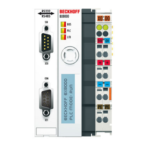
Fig. 2 BX8000
Introduction
Fig. 3 the Principle of the Bus Terminal
Technical Data
Technical Data - PLC
Fig. 4 BX3100, BX5100, BX5200, BX9000
3 Mounting and Wiring
Fig. 5 BX8000
Fig. 6 Released BX Controller
Installation on Mounting Rails
Fig. 7 Latched BX Controller
Fig. 8 Disassembly
Wiring
Fig. 9 Potential Groups of a Bus Terminal Block
Fig. 10 Power Contact on the Left
Power Supply
Fig. 11 Terminal Points for the Bus Terminal Controller Supply
Fig. 12 UL Identification
Fig. 13: Programming Cable ZK1000-0030 - COM 1 and COM 2
Programming Cable for COM1
Fig. 14 Programming Cable ZK1000-0030 - Plug Connector Dimensions
Fig. 15 Programming Cable ZK1000-0030 - Pinning
SSB and COM Interface
Fig. 16 SSB Interface
Fig. 17 COM1 (RS 232) and COM2 (RS 232/485) Interface
Fig. 18 Start-Up Behavior of the Bus Terminal Controller
4 Parameterization and Commissioning
Configuration
Fig. 19 Creating a Twincat Configuration
Fig. 20 Selecting the Bus Terminal Controller
Fig. 21 Downloading a Twincat Configuration
Fig. 22 Selecting the Bus Terminal Controller
Fig. 23 State of the Bus Terminal Controller
Fig. 24 Activating the Twincat Configuration
Uploading a Twincat Configuration
Fig. 25 Choose Target System
Fig. 26 Selecting the Bus Terminal Controller
Fig. 27 State of the Bus Terminal Controller
Fig. 28 Uploading the Twincat Configuration
Fig. 29 Memory for Code Mapping
Resources in the Bus Terminal Controller
Fig. 30 Data Memory Mapping
Fig. 31 Code and Data Memory
Fig. 32 Other Memory
ADS Connection Via Serial Interface
Fig. 33 Properties of the Remote Connection
Fig. 34 BX Settings Tab
K-Bus
Fig. 35 BX Diag Tab
Fig. 36 Selecting the PLC Project
Fig. 37 Connecting PLC Variable and Hardware
Fig. 38 Target System Display
Fig. 39 Setting the Task Time
Fig. 40 Displaying the PLC Cycle Time
Fig. 41 Termination of the Bus with a 120 Ohm Termination Resistor
Fig. 42 Insensitivity to Incoming Interference
Fig. 43 Sample Topology of Drop Lines
Fig. 44 Structure of CAN Cable ZB5100
Real-Time Clock (RTC)
COM Port
Menu
Creating Own Menus
Programming
Allocated Flags
Persistent Data
Local Process Image in Delivery State (Default Config)
Twincat PLC - Error Codes
Mapping the Bus Terminals
Local Process Image in the Twincat Configuration
Creating a Boot Project
Up- and Downloading of Programs
Libraries
Tcbasebx
Fig. 91 Function Block F_COMPORTWRITE
Fig. 92 Function Block FB_COMPORTOPEN
Fig. 93 Function Block FB_COMPORTCLOSE
Fig. 94 Function Block F_STARTDEBUGTIMER
Fig. 95 Function Block F_READDEBUGTIMER
Fig. 96 Function Block F_GETNAVSWITCH
Fig. 97 Function Block FB_DISPWRITE
Fig. 98 Function Block RTC
Tcsystembx
Fig. 99 Function Block Fb_Readwritefile
Fig. 100 Function Block Fb_Bx_Bk8X00_Master
Tccomportbx
Fig. 101 Function Block FB_BX_BK8X00_SLAVE
Fig. 102 Communication Features
Fig. 103 Function Block FB_BX_COM_5
Fig. 104 Function Block FB_BX_COM_64
Fig. 105 Function Block FB_BX_COM_64EX
Fig. 106 Cimrex Panel at the COM Port of the BX Controller
Fig. 107 Mobile Phone at the COM Port of the BX Controller
Tctwinsafe
Fig. 108 Function Block F_GETVERSIONTCTWINSAFE
Fig. 109 Function Block FB_TWINSAFE_KLX904_INPUT
Fig. 110 Function Block Fb_Twinsafe_Klx904_Input
Fig. 111 Linking the Input Data
Fig. 112 Selecting the Safetyin Variable
Fig. 113 Function Block Fb_Twinsafe_Klx904_Output
Fig. 114 Call of Function Block FB_TWINSAFE_KLX904_OUTPUT
Fig. 115 Call of Function Block FB_TWINSAFE_KLX904_OUTPUT
Fig. 116 Linking the Input Data
Fig. 117 Selecting the Corresponding Safetyqbx Variable
Fig. 118 Selecting the Data Transfer Route - Serial Interface
Fig. 119 Parameterization of the Serial Interface
Program Transfer Via the Serial Interface
Fig. 120 Selecting the Data Transfer Route - AMS
Fig. 121 Selecting the Device
Fig. 122 State of the K-Bus
6 Error Handling and Diagnosis
Fig. 123 Diagnostic Leds for the PLC, the K-Bus and the Power Supply
Fig. 124 Diagnostic Leds for the PLC and the K-Bus
Diagnostics Display
7 Appendix
Fig. 125 Selecting a BX Series Bus Terminal Controller
Firmware Update
Fig. 126 Selecting a BC Series Bus Terminal Controller
Fig. 127 Select the COM Port
Fig. 128 Open the Firmware File
Fig. 129 Status Messages Relating to the Firmware Update
Fig. 130 CFC Client
Fig. 131 Call the Port Setup
Fig. 132 Set the COM Parameters
Fig. 133 Open the COM Port
Fig. 134 Upload the BX Memory Content to a bin File
Fig. 135 Downloading a bin File to the BX Controller
Sample Programs - Overview
Fig. 136 Name Plate of a BX Controller
Test Standards for Device Testing
Support and Service
List of Illustrations
Advertisement
Quick Links
1
Fig. 13: Programming Cable Zk1000-0030 - Com 1 and Com 2
Download this manual
Documentation
BX8000
Bus Terminal Controller for RS232/RS485
Version:
Date:
2.1.0
2019-06-14
Table of
Contents
Previous
Page
Next
Page
1
2
3
4
5
Advertisement
Chapters
Table of Contents
3
List of Illustrations
147
Table of Contents
Need help?
Do you have a question about the BX Series and is the answer not in the manual?
Ask a question
Questions and answers
Related Manuals for Beckhoff BX Series
Controller Beckhoff BK7300 User Manual
(8 pages)
Controller Beckhoff BC9000 Documentation
Bus terminal controller for ethernet (90 pages)
Controller Beckhoff BC9100 Documentation
Bus terminal controller for ethernet (90 pages)
Controller Beckhoff BX8000 Documentation
Bus terminal controller (149 pages)
Controller Beckhoff BC**50 Series Documentation
Bus terminal controller for devicenet (90 pages)
Controller Beckhoff BC5250 Documentation
Bus terminal controller for devicenet (90 pages)
Controller Beckhoff BC8050 Documentation
Bus terminal controller with rs485 or rs232 interface (93 pages)
Controller Beckhoff BC8150 Documentation
Bus terminal controller with rs485 or rs232 interface (93 pages)
Controller Beckhoff BC2000 Technical Documentation Manual
Bus terminal controller (28 pages)
Controller Beckhoff BC7300 Manual
Modbus bus terminal controller (48 pages)
Controller Beckhoff BC3150 Documentation
Bus terminal controller for profibus-dp (104 pages)
Controller Beckhoff CX8080 Documentation
The cx8080 is a controller with an ethernet port and two serial interfaces (67 pages)
Controller Beckhoff C6930 Installation And Operating Instructions Manual
Control cabinet pc (31 pages)
Controller Beckhoff C9900-G00 Series Manual
Push button extension (45 pages)
Controller Beckhoff CX90 0 Series Hardware Documentation
Ethernet controller (61 pages)
Controller Beckhoff EK1960 Series Operating Instructions Manual
Twinsafe compact controller (145 pages)
This manual is also suitable for:
Bx8000
Bx3100
Bx9000
Bx5100
Bx5200
Table of Contents
Print
Rename the bookmark
Delete bookmark?
Delete from my manuals?
Login
Sign In
OR
Sign in with Facebook
Sign in with Google
Upload manual
Upload from disk
Upload from URL


Need help?
Do you have a question about the BX Series and is the answer not in the manual?
Questions and answers