Table of Contents
Advertisement
Advertisement
Table of Contents

Related Manuals for Beckhoff BC7300


Summary of Contents for Beckhoff BC7300
- Page 1 MODBUS Bus Terminal Controller BC7300 Version: 1.5 Last change: 2006-11-06...
- Page 2 © This manual is copyrighted. Any reproduction or third party use of this protected publication, whether in whole or in part, without the written permission of Elektro Beckhoff GmbH, is forbidden. BC7300...
-
Page 3: Table Of Contents
Liability Conditions Delivery conditions Copyright Safety Instructions State at Delivery Description of safety symbols 2. Basic Principles Device Description of the BC7300 The Beckhoff Bus Terminal System The interfaces Electrical power supply Power contacts feeding points Power contacts Fieldbus connection... - Page 4 The Program in the Bus Terminal Controller Creating the BOOT Program MODBUS Communication 6. Questions and Answers General No communication with the BC7300 Mapping of the digital and the byte-oriented Bus Terminals onto a fixed address Drop of the digital outputs 7. Index 8.
-
Page 5: Foreword
In addition, the general delivery conditions of the company Beckhoff Automation GmbH apply. Copyright © This documentation is copyrighted. Any reproduction or third party use of this publication, whether in whole or in part, without the written permission of Beckhoff Automation GmbH, is forbidden. BC7300... -
Page 6: Safety Instructions
All the components are supplied in particular hardware and software configurations appropriate for the application. Modifications to hardware or software configurations other than those described in the documentation are not permitted, and nullify the liability of Beckhoff Automation GmbH. Description of safety symbols The following safety symbols are used in this documentation. -
Page 7: Basic Principles
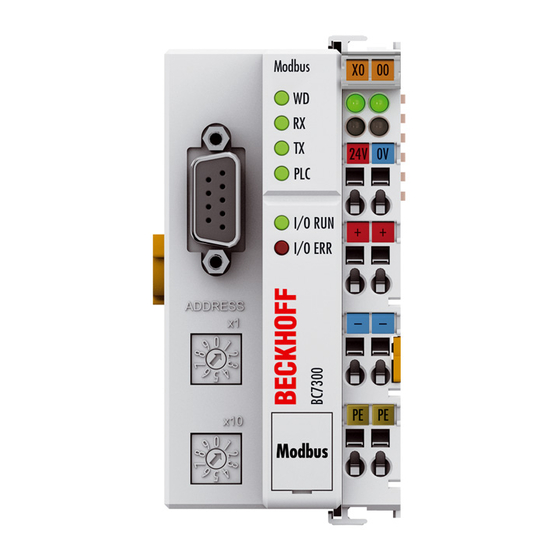
Basic Principles Basic Principles Device Description of the BC7300 The BC7300 Bus Terminal Controller is a Bus Coupler with integrated PLC functionality and a MODBUS slave interface. The controller is programmed in IEC 1131-3. Up to 64 terminals belonging to the Beckhoff Bus Terminal System can be connected to the BC7300. - Page 8 Bus Coupler Potential The principle of the Bus Terminal power input Bus Coupler supply terminal End Terminal BC7300 K-Bus MODBUS PE PE Potential Power isolation contacts Additional characteristics of Bus Terminal Controllers (BC) differ from Bus Couplers (BK) in that, in the Bus Terminal addition to K-Bus processing, a real-time PLC task is also running.
-
Page 9: The Interfaces
The MODBUS – Bus MODBUS Power LEDs Terminal Controller Bus Coupler / power contacts BC7300 K-Bus MODBUS Bus Coupler power supply 24 V DC / GND Configuration and Power contacts... -
Page 10: Configuration And Programming Interface
The miniature connector can be joined to a PC with the aid of a connecting cable and either the KS2000 configuration software or TwinCAT BC. The interface allows the analog channels to be configured with the KS2000 software. The BC7300 is programmed via the same interface. KS2000 Software... -
Page 11: Operating Modes Of The Bus Terminal Controller
Communication start Mechanical structure The system of the Beckhoff Bus Terminals is characterised by low physical volume and high modularity. When planning a project it must be assumed that at least one Bus Coupler and a number of Bus Terminals will be used. - Page 12 The transfer of the data and the supply voltage for the intelligent electronics in the Bus Terminals is performed by the K-Bus. The supply of the field electronics is performed for the digital Bus Terminals through the power contacts. BC7300...
- Page 13 10 mm out from the connected group of other terminals. In that case, the PE conductors do not have to be disconnected. PE power contacts The “PE” power contact must not be used for other potentials. BC7300...
-
Page 14: Technical Data
Bus Coupler that is available for supply of the Bus Terminals. A special power supply terminal (KL9400) can be inserted at any location to insert more power into the K-Bus. Refer to Beckhoff’s technical support department regarding the use of a power supply terminal. -
Page 15: Peripheral Data In The Process Image
The assignment starts on the left next to the Bus Coupler. The software in the Bus Coupler collects the individual entries for each of the channels in order to create the assignment list counting from left to right. BC7300... -
Page 16: Start-Up Procedure And Diagnostics
Bus Terminals and the connections to these terminals. The green LED lights up in order to indicate fault-free operation. The red LED blinks with two different frequencies in order to indicate an error. BC7300... - Page 17 Exchange Bus Terminals communication with Bus Terminal n 9 pulses Checksum error in program flash Transmit program to the BC7300 again memory n (n>0) Bus Terminal n is not consistent with Check the n Bus Terminal. If a new Bus...
-
Page 18: Fieldbus Errors
Once a WD error has occurred, data communication can only be restarted by resetting the coupler (see "Coupler Reset", under Diagnostics). The maximum watchdog time is 65000 ms, and it can be set by rotary switch or via the KS2000 software. BC7300... -
Page 19: Modbus
Preset multiple register • PIN assignment The BC7300 uses RS485 for the data transmission. A screened two-wire cable is sufficient. The connection to the coupler is a 9-pin sub-D socket. The data line is connected to PIN 3 and PIN 8. -
Page 20: Process Data And Memory Map
The PLC variables offer an interface between these two process images. MODBUS The input process image of the BC7300 starts from address 0x0000. All the byte-oriented Bus Terminals (see Appendix) are entered here into the process image first. The bit-oriented Bus Terminals them follow, and each word (16 bit) is filled before starting a new one. - Page 21 POS 3 KL2012 MODBUS terminal POS 4 KL2012 BC7300 terminal POS 5 KL3002 MODBUS terminal POS 6 KL3002 BC7300 complex terminal POS 7 KL3002 BC7300 compact terminal POS 8 KL4032 MODBUS terminal POS 9 KL4032 BC7300 complex terminal POS 10...
-
Page 22: Modbus Process Image
0x0008 16 bit 0x0009 16 bit 0x000A 16 bit BC7300 Process Image Byte address Terminal Inputs Terminal Outputs Example for the BC7300 KL3002 (POS 6) Status KL3002 Control (POS 6) Data 0 Data 0 Data 1 Data 1 Status Control... -
Page 23: Assignment Of The Bus Terminals
In the default setting, all the Bus Terminals are assigned to the Bus Terminal Controller. This can be changed with the KS2000 software. The assignment of the terminals is specified in Table 1 of the BC7300. Description The Bus Terminal is assigned to the MODBUS, and byte-... -
Page 24: Setting And Parameterisation Of The Modbus
BC7300. Only the Bus Terminal Controller's end terminal may be inserted for this. Only plug the KL9010 into the BC7300. Use the rotary switch to select the parameters. The x10 address switch is used to select the parameter, while the x1 address switch is used for the associated setting. The settings can be found in the table. -
Page 25: Parameterisation Table
In ms for RTU mode (0 dependent on the baud rate) In seconds for ASCII mode (0 EOF time switched off) Watchdog 100 ms 5 0..9 Watchdog x 100 ms Watchdog 1000 ms 6 0..9 Watchdog x 1000 ms Factory setting 9 BC7300... -
Page 26: The Modbus Protocol
(illustrated in the diagram with T1-T2-T3-T4). The characters permitted for transmission in all fields are hexadecimal 0... 9, A..., F. RTU frame Start Addres Functio Data Check T1-T2- T1-T2- T3-T4 charact charact charact charact T3-T4 BC7300... -
Page 27: Functions
The query was for 10 bits, and these are now distributed over 2 bytes. The third bit in the output process image of the BC7300 is set, and the Bus Coupler returns a "4" in the first data byte. -
Page 28: Read Digital Inputs (Function 2)
The query was for 10 bits, and these are now distributed over 2 bytes. The first bit in the input process image of the BC7300 is set, and the Bus Coupler returns a "1" in the first data byte. -
Page 29: Read Analog Inputs (Function 4)
LRC / CRC 0x61 End of frame t1-t2-t3 CRLF 0xD, 0xA Response The Bus Terminal Controller answers with byte count 4, i.e. 4 bytes of data are returned. The query was for 2 analog channels, and these will now be BC7300... -
Page 30: Writing A Digital Output (Function 5)
The first analog output of slave number 11 is written with function 6. The analog outputs begin at offset 0x0800 (hex). Here again the offset always describes a word. This means offset 0x0803 refers to the fourth word in the output process image. BC7300... -
Page 31: Writing A Number Of Digital Outputs (Function 15)
Example: 20 bits – corresponds to 24 bits – count is 3 bytes (round up to the nearest byte) The data bytes contain the values for the individual bits. In this example, the first 16 bits are set to "TRUE", while bits 17 to 20 are "FALSE". BC7300... -
Page 32: Writing A Number Of Analog Outputs (Function 16)
The data bytes contain the values for the analog outputs. In this example, two words are to be written. The first word is to receive the value 0x7FFF (hex), and the second word is to receive the value 0x3FFF. BC7300... -
Page 33: Writing And Reading Analog Outputs And Inputs
The data bytes contain the values for the analog outputs. In this example, two words are to be written. The first word is to receive the value 0x3FFF (hex), and the second word is to receive the value 0x7FFF. BC7300... - Page 34 The slave outputs the function code and the sub-function code as an answer. The diagnostic queries use a two-byte data field to send diagnostics data or control information to the slave. BC7300...
-
Page 35: Echoes A Query (Sub-Function 0)
Sub-function 0 causes the data that is sent to the slave by the master to be returned. Bus Coupler Reset (Sub-Function 1) Sub-function 1 re-initialises the BC7300. Error counters are reset, and the coupler executes a self-test. No telegrams are either received or sent while the coupler is being reset. -
Page 36: Slave Answers (Sub-Function 14)
Data field (response) 00 0F 00 00 Slave Response Count Number of Error Answers (Sub-Function 16) Contains the number of error answers that the slave has sent. Sub-function Data field (query) Data field (response) 00 10 00 00 Number error answers BC7300... -
Page 37: Bc7300 Error Answers
When the user sends the slave either a request or information that the Bus EXCEPTION RESPONSE Coupler does not understand, the BC7300 responds with an error report. This answer contains the function and the error code. 0x80 is added to the value returned by the function. -
Page 38: Bus Terminal Controller
Before initiating the program, the Bus Terminal Controller executes a K-Bus update, in order to interrogate the inputs. After the program has been executed, the BC7300 carries out another K-Bus update, in order to write the current outputs. The background time follows this. -
Page 39: Persistent Data
The Persistent Variable memory area must always be smaller or equal than that of the Retain Variables. The KS2000 software allows this area to be increased to a maximum of 512 bytes (Table 1, Register 18). These data are deleted by a general reset. From Firmware B4 BC7300... -
Page 40: Allocated Flags Area
From the firmware B4 is it as well possible to access directly reading and writing on the flag area. This access does not trigger the watchdog. That means values which are written in this range, remain as well after a watchdog error set. BC7300... -
Page 41: Appendix
Terminal bus diagnostics must however be activated for this purpose. The 2-byte diagnostic interface occupies two bytes each of output and input data. They are handled using a special protocol. A description of the 2 byte-diagnostic interface can be supplied on request. From Firmware B4 BC7300... -
Page 42: Mapping The Bus Terminals
To update your firmware you need the KS2000 software and the appropriate serial cable, supplied along with KS2000. You may find the firmware under www.Beckhoff.de. Table Firmware Description B1 Released version B2 PLC optimized B3 Internal version B4 Modbus access to flag range BC7300... -
Page 43: Example Program
This is included when TwinCAT BC or KS2000 is supplied. The first step is to create a program in the BC7300. For this purpose the address selection switch is set to "00". This it the programming mode for the Bus Terminal Controller. -
Page 44: Creating The Boot Program
Bus Terminal Controller off and then on again. Remove the programming cable, and connect the MODBUS cable. MODBUS Communication Function 4 is used in order to obtain the states of the counters in the two 16-bit output words in the MODBUS master. BC7300... - Page 45 Data 1 high byte 0 0x00 Address %QB129 Data 1 low byte 56 0x38 Address %QB128 Data 2 high byte 63 0x3F Address %QB131 Data 2 low byte 11 0x0B Address %QB130 Error Check 0x80 LRC / CRC 0x7E End of frame t1-t2-t3 BC7300...
-
Page 46: Questions And Answers
Questions and Answers Questions and Answers General No communication with the BC7300 Problem You cannot log in with either KS2000 nor TwinCAT (BC). Solution Set the address selection switch to "00" and start the Bus Terminal Controller again. Mapping of the digital and the byte-oriented Bus Terminals... -
Page 47: Index
Writing a number of analog outputs Writing a number of digital outputs Interfaces Writing an analog output K-Bus 6, 12 If you have suggestions to make or ideas about our documentation, please send us an e-mail, stating the version number, at Dokumentation@Beckhoff.de. BC7300... -
Page 48: Support And Service
Please contact your Beckhoff branch office or representative for local support and service on Beckhoff products! The addresses of Beckhoff's branch offices and representatives round the world can be found on her internet pages: http://www.beckhoff.com You will also find further documentation for Beckhoff components there.
Need help?
Do you have a question about the BC7300 and is the answer not in the manual?
Questions and answers