Emerson Micro Motion 2700 Configuration And Use Manual
With foundation fieldbus
Hide thumbs
Also See for Micro Motion 2700:
- Configuration and use manual (374 pages) ,
- Installation manual (80 pages) ,
- Configuration and use manual supplement (44 pages)

Subscribe to Our Youtube Channel
Related Manuals for Emerson Micro Motion 2700


Summary of Contents for Emerson Micro Motion 2700
- Page 1 Configuration and Use Manual 20000326, Rev ED April 2018 ® Micro Motion Model 2700 Transmitters with ™ FOUNDATION Fieldbus Configuration and Use Manual...
- Page 2 Micro Motion employees. Micro Motion will not accept your returned equipment if you fail to follow Micro Motion procedures. Return procedures and forms are available on our web support site at www.emerson.com, or by phoning the Micro Motion Customer Service department.
-
Page 3: Table Of Contents
Contents Contents Part I Getting started Chapter 1 Before you begin ......................3 About this manual ........................3 Communication methods ......................3 Additional documentation and resources ..................4 Chapter 2 Quick start ........................5 Power up the transmitter ......................5 Check meter status ........................5 2.2.1 Transmitter status reported by LED ................6 Determine the FOUNDATION Fieldbus unique device ID ..............7... - Page 4 Contents 4.5.2 Configure two-phase flow parameters ................ 34 4.5.3 Configure Density Damping ..................35 4.5.4 Configure Density Cutoff ....................36 Configure temperature measurement ..................37 4.6.1 Configure Temperature Measurement Unit ..............37 4.6.2 Configure Temperature Damping ................38 4.6.3 Effect of Temperature Damping on process measurement ......... 39 Configure the petroleum measurement application ..............
- Page 5 Contents Back up transmitter configuration ..................... 71 Return function blocks to In Service (Auto) mode ..............72 Part III Operations, maintenance, and troubleshooting Chapter 7 Transmitter operation ....................75 Record the process variables ..................... 75 View process variables .......................76 7.2.1 View process variables using the display ..............76 7.2.2 View process variables and other data using ProLink III ..........77...
- Page 6 Contents Check the drive gain ........................ 122 9.9.1 Collect drive gain data ....................123 9.10 Check the pickoff voltage ......................123 9.10.1 Collect pickoff voltage data ..................124 9.11 Check for internal electrical problems ..................124 9.11.1 Check the sensor coils ....................124 Appendices and reference Appendix A Transducer blocks and views ..................127...
- Page 7 Contents A.8.3 Process variables for concentration measurement transducer blocks ....... 225 A.8.4 Totals for concentration measurement transducer blocks ........226 A.8.5 Setup data for concentration measurement transducer blocks ......... 227 A.8.6 Other additions for concentration measurement transducer blocks ......232 Density viscosity meter transducer blocks ................
- Page 8 Contents Appendix D Using the transmitter display ..................299 Using the display ........................299 D.1.1 Components of the transmitter interface ..............299 D.1.2 Use the optical switches ....................300 D.1.3 Access and use the display menu system ..............300 D.1.4 Display codes for process variables ................305 D.1.5 Codes and abbreviations used in display menus ............306 Appendix E...
-
Page 9: Getting Started
Getting started Part I Getting started Chapters covered in this part: • Before you begin • Quick start Configuration and Use Manual... - Page 10 Getting started Micro Motion Model 2700 Transmitters with FOUNDATION Fieldbus...
-
Page 11: Before You Begin
Before you begin Before you begin Topics covered in this chapter: • About this manual • Communication methods • Additional documentation and resources About this manual This manual helps you configure, commission, use, maintain, and troubleshoot ™ Micro Motion Model 2700 transmitters with FOUNDATION fieldbus. -
Page 12: Additional Documentation And Resources
Topic Document Hazardous area installa- See the approval documentation shipped with the transmitter, or tion download the appropriate documentation at www.emerson.com. ™ Product Data Sheet Micro Motion Series 1000 and Series 2000 Transmitters with MVD Tech‐ nology Product Data Sheet... -
Page 13: Chapter 2 Quick Start
Quick start Quick start Topics covered in this chapter: • Power up the transmitter • Check meter status • Determine the FOUNDATION Fieldbus unique device ID • Make a startup connection to the transmitter • Verify mass flow measurement Power up the transmitter The transmitter must be powered up for all configuration and commissioning tasks, or for process measurement. -
Page 14: Transmitter Status Reported By Led
Quick start Wait approximately 10 seconds for the power-up sequence to complete. Immediately after power-up, the transmitter runs through diagnostic routines and checks for error conditions. During the power-up sequence, Alert A009 is active. This alert should clear automatically when the power-up sequence is complete. Check the status LED on the transmitter. -
Page 15: Determine The Foundation Fieldbus Unique Device Id
Quick start Determine the FOUNDATION Fieldbus unique device ID The transmitter is shipped with a sticker that displays a unique 32-digit number that the fieldbus segment uses for identification. If the sticker is missing, use this procedure to determine your device ID. From ProLink III, navigate to Device Tools >... - Page 16 Quick start Micro Motion Model 2700 Transmitters with FOUNDATION Fieldbus...
-
Page 17: Part Ii Configuration And Commissioning
Configuration and commissioning Part II Configuration and commissioning Chapters covered in this part: • Introduction to configuration and commissioning • Configure process measurement • Configure device options and preferences • Complete the configuration Configuration and Use Manual... - Page 18 Configuration and commissioning Micro Motion Model 2700 Transmitters with FOUNDATION Fieldbus...
-
Page 19: Introduction To Configuration And Commissioning
Introduction to configuration and commissioning Introduction to configuration and commissioning Topics covered in this chapter: • Configuration flowchart • Default values and ranges • Enable access to the off‐line menu of the display • Disable write‐protection on the transmitter configuration •... - Page 20 Introduction to configuration and commissioning Figure 3-1: Configuration flowchart Configure device options and preferences Test and move to production Configure process measurement Configure mass flow Test or tune transmitter Configure display measurement using sensor simulation parameters Configure volume flow meaurement Configure fault handling Back up transmitter parameters...
-
Page 21: Default Values And Ranges
Introduction to configuration and commissioning Default values and ranges Section G.1 to view the default values and ranges for the most commonly used parameters. Enable access to the off-line menu of the display Display OFF-LINE MAINT > OFF-LINE CONFG ProLink III Device Tools >... -
Page 22: Place Function, Transducer, And Resource Blocks In Oos Mode
Introduction to configuration and commissioning Place function, transducer, and resource blocks in OOS mode Before you modify parameters on the fieldbus function, transducer, and resource blocks, you must place the blocks in Out of Service (OOS) mode. Before you return the device to operation, you must place them back in service (Auto mode). -
Page 23: Restore The Factory Configuration
Introduction to configuration and commissioning Restore the factory configuration Display Not available ProLink III Device Tools > Configuration Transfer > Restore Factory Configuration Field Communicator Service Tools > Maintenance > Reset/Restore > Master Reset Fieldbus host Diagnostic TB > Restore Factory Config (OD Index 056) Overview Restoring the factory configuration returns the transmitter to a known operational configuration. - Page 24 Introduction to configuration and commissioning Micro Motion Model 2700 Transmitters with FOUNDATION Fieldbus...
-
Page 25: Configure Process Measurement
Configure process measurement Configure process measurement Topics covered in this chapter: • Configure mass flow measurement • Configure volume flow measurement for liquid applications • Configure GSV flow measurement • Configure flow direction • Configure density measurement • Configure temperature measurement •... - Page 26 Configure process measurement Options for Mass Flow Measurement Unit The transmitter provides a standard set of measurement units for Mass Flow Measurement Unit, plus one user-defined special measurement unit. Different communications tools may use different labels for the units. Label Display ProLink III Field Communica-...
- Page 27 Configure process measurement Define a special measurement unit for mass flow Display Not available ProLink III Device Tools > Configuration > Process Measurement > Flow > Special Units Field Communicator Configure > Manual Setup > Measurements > Special Units > Mass Special Units Fieldbus host Measurement TB >...
-
Page 28: Configure Flow Damping
Configure process measurement Example: Defining a special measurement unit for mass flow You want to measure mass flow in ounces per second (oz/sec). Set Base Mass Unit to Pounds (lb). Set Base Time Unit to Seconds (sec). Calculate Mass Flow Conversion Factor: a. -
Page 29: Configure Mass Flow Cutoff
Configure process measurement • In general, lower damping values are preferable because there is less chance of data loss, and less lag time between the actual measurement and the reported value. The value you enter is automatically rounded off to the nearest valid value. For example, if the damping is currently set to 0.8 seconds, any value entered up to 1.2 seconds will be rounded down to 0.8 seconds, and any value entered from 1.21 to 1.59 seconds will be rounded up to 1.6 seconds. -
Page 30: Configure Volume Flow Measurement For Liquid Applications
Configure process measurement Configure volume flow measurement for liquid applications The volume flow measurement parameters control how liquid volume flow is measured and reported. Restriction You cannot implement both liquid volume flow and gas standard volume flow at the same time. Choose one or the other. - Page 31 Configure process measurement Overview Volume Flow Measurement Unit specifies the unit of measurement that will be displayed for the volume flow rate. The unit used for the volume total and volume inventory is based on this unit. Prerequisites Before you configure Volume Flow Measurement Unit, be sure that Volume Flow Type is set to Liquid.
- Page 32 Configure process measurement Label Unit description Display ProLink III Field Communicator l/hr Liters per hour Million liters per day MILL/D mil l/day ML/d UKGPS Imp gal/sec Impgal/s Imperial gallons per second UKGPM Imp gal/min Impgal/min Imperial gallons per minute UKGPH Imp gal/hr Impgal/h Imperial gallons per hour...
-
Page 33: Configure Volume Flow Cutoff
Configure process measurement The special unit label displays only on the local display. The AI block uses and displays the actual engineering unit (i.e. L/min). Procedure Specify Base Volume Unit. Base Volume Unit is the existing volume unit that the special unit will be based on. Specify Base Time Unit. -
Page 34: Configure Gsv Flow Measurement
Configure process measurement Overview Volume Flow Cutoff specifies the lowest volume flow rate that will be reported as measured. All volume flow rates below this cutoff are reported as 0. Procedure Set Volume Flow Cutoff to the value you want to use. The default value for Volume Flow Cutoff is 0.0 l/sec (liters per second). -
Page 35: Configure Standard Density Of Gas
Configure process measurement Procedure Set Volume Flow Type to Gas Standard Volume. 4.3.2 Configure Standard Density of Gas Display Not available ProLink III Device Tools > Configuration > Process Measurement > Flow Field Communicator Configure > Manual Setup > Measurements > GSV > Gas Ref Density Fielbus host Measurement TB >... - Page 36 Configure process measurement The default setting for Gas Standard Volume Flow Unit is SCFM (Standard Cubic Feet per Minute). If the measurement unit you want to use is not available, you can define a special measurement unit. Options for Gas Standard Volume Flow Unit The transmitter provides a standard set of measurement units for Gas Standard Volume Flow Unit, plus one user-defined special measurement unit.
- Page 37 Configure process measurement Define a special measurement unit for gas standard volume flow Display Not available ProLink III Device Tools > Configuration > Process Measurement > Flow > Special Units Field Communicator Configure > Manual Setup > Measurements > Special Units > Special GSV Units Fieldbus host Measurement TB >...
-
Page 38: Configure Gas Standard Volume Flow Cutoff
Configure process measurement The special measurement unit is stored in the transmitter. You can configure the transmitter to use the special measurement unit at any time. Example: Defining a special measurement unit for gas standard volume flow You want to measure gas standard volume flow in thousands of standard cubic feet per minute. -
Page 39: Configure Flow Direction
Configure process measurement Configure flow direction Display Not available ProLink III Device Tools > Configuration > Process Measurement > Flow Field Communicator Configure > Manual Setup > Measurements > Flow > Flow Direction Fieldbus host Measurement TB > FLOW_DIRECTION {OD Index 41) Overview Flow Direction controls how forward flow and reverse flow affect flow measurement and reporting. - Page 40 Configure process measurement Flow Direction setting Relationship to Flow Direction arrow ProLink III Field Communicator on sensor Negate Forward Negate/Forward Only Appropriate when the Flow Direction ar- row is in the opposite direction from the majority of flow. Negate Bidirectional Negate/Bi-directional Appropriate when both forward and re- verse flow are expected, and reverse flow...
-
Page 41: Configure Density Measurement
Configure process measurement Configure density measurement The density measurement parameters control how density is measured and reported. 4.5.1 Configure Density Measurement Unit Display OFF-LINE MAINT > OFF-LINE CONFG > UNITS > DENS ProLink III Device Tools > Configuration > Process Measurement > Density Field Communicator Configure >... -
Page 42: Configure Two-Phase Flow Parameters
Configure process measurement Label Unit description Display ProLink III Field Communicator D API degAPI degAPI Degrees API (1) Non‐standard calculation. This value represents line density divided by the density of water at 4 °C. 4.5.2 Configure two-phase flow parameters Display Not available ProLink III Device Tools >... -
Page 43: Configure Density Damping
Configure process measurement You must enter Two-Phase Flow High Limit in g/cm³, even if you configured another unit for density measurement. Set Two-Phase Flow Timeout to the number of seconds that the transmitter will wait for a two-phase flow condition to clear before posting the alert. The default value for Two-Phase Flow Timeout is 0.0 seconds, meaning that the alert will be posted immediately. -
Page 44: Configure Density Cutoff
Configure process measurement Damping is used to smooth out small, rapid fluctuations in process measurement. Damping Value specifies the time period (in seconds) over which the transmitter will spread changes in the process variable. At the end of the interval, the internal value will reflect 63% of the change in the actual measured value. -
Page 45: Configure Temperature Measurement
Configure process measurement Overview Density Cutoff specifies the lowest density value that will be reported as measured. All density values below this cutoff will be reported as 0. Procedure Set Density Cutoff to the value you want to use. For most applications, the default setting (0.2 g/cm³) is sufficient. The range is 0.0 g/cm³ to 0.5 g/cm³. -
Page 46: Configure Temperature Damping
Configure process measurement Label Field Communica- Unit description Display ProLink III °C °C degC Degrees Celsius Degrees Fahrenheit °F °F degF °R °R degR Degrees Rankine °K °K Kelvin 4.6.2 Configure Temperature Damping Display Not available ProLink III Device Tools > Configuration > Temperature Field Communicator Configure >... -
Page 47: Effect Of Temperature Damping On Process Measurement
Configure process measurement • In general, lower damping values are preferable because there is less chance of data loss, and less lag time between the actual measurement and the reported value. The value you enter is automatically rounded off to the nearest valid value. Valid values for Temperature Damping are 0, 0.6, 1.2, 2.4, 4.8, …... - Page 48 Configure process measurement Prerequisites You will need API documentation for the API table that you select. Depending on your API table, you may need to know the thermal expansion coefficient (TEC) for your process fluid. You must know the reference temperature that you want to use. Procedure Choose Device Tools >...
-
Page 49: Configure Petroleum Measurement Using The Field Communicator
Configure process measurement b. Verify that the referred density range of the selected table is adequate for your application. If you chose a C table, enter Thermal Expansion Coefficient (TEC) for your process fluid. Set Reference Temperature to the temperature to which density will be corrected in referred density calculations. - Page 50 Configure process measurement Table name Process fluid CTL source data Reference temperature Density unit Generalized crude and Observed density and 60 °F (non-configurable) Degrees API observed temperature Range: 0 to 100 Generalized products Observed density and 60 °F (non-configurable) Degrees API observed temperature Range: 0 to 85 Lubricating oils...
-
Page 51: Set Up Concentration Measurement
Configure process measurement Set up concentration measurement This section guides you through loading and setting up a concentration matrix used for measurement. It does not cover building a concentration matrix. The concentration measurement application calculates concentration data from process temperature and density. Micro Motion provides a set of concentration matrices that provide the reference data for several standard industry applications and process fluids. -
Page 52: Configure Concentration Measurement Using The Field Communicator
Configure process measurement • If you change the setting of Derived Variable, all existing concentration matrices will be deleted from transmitter memory. Set Derived Variable before loading concentration matrices. Load one or more matrices. a. Set Matrix Being Configured to the location to which the matrix will be loaded. b. - Page 53 Configure process measurement Choose Online > Configure > Manual Setup > Measurements > Temperature and set Temperature Unit to match the temperature unit used by your matrix. Choose Online > Configure > Manual Setup > Measurements and click Concentration Measurement. Set up extrapolation alerts.
-
Page 54: Standard Matrices For The Concentration Measurement Application
Configure process measurement Option Setup A value written by a. Choose Online > Configure > Manual Setup > Measurements > digital communica- External Inputs tions b. Enable External Temperature. c. Perform the necessary host programming and communications setup to write temperature data to the transmitter at appropri- ate intervals. -
Page 55: Derived Variables And Calculated Process Variables
Configure process measurement Temperature Matrix name Description Density unit unit Derived variable HFCS 42 °C Mass Concentration Matrix represents a hydrometer scale g/cm (Density) for HFCS 42 (high-fructose corn syrup) solutions that indicates the percent by mass of HFCS in solution. HFCS 55 Matrix represents a hydrometer scale g/cm... -
Page 56: Set Up Concentration Measurement Using A Basic Ff Host
Configure process measurement Calculated process variables Density at reference Standard Derived tempera- volume Specific Concen- Net mass volume Variable Description ture flow rate gravity tration flow rate flow rate ✓ ✓ ✓ ✓ ✓ Mass The percent mass of Concentration solute or of material in (Specific Gravity) suspension in the total... -
Page 57: Set Reference Temperature Values For Specific Gravity Using A Basic Ff Host
Configure process measurement 4.9.1 Set reference temperature values for specific gravity using a basic FF host When Derived Variable is set to any option based on specific gravity, you must set the reference temperature for water, then verify the density of water at the configured reference temperature. -
Page 58: Modify Extrapolation Alerts For Concentration Measurement Using A Basic Ff Host
Configure process measurement Table 4-3: Concentration unit codes Fieldbus code Unit 1110 degTwad 1426 degBrix 1111 degBaum hv 1112 degBaum It 1343 % sol/wt 1344 % sol/vol 1427 degBall 1428 proof/vol 1429 proof/mass 1346 % plato special Write a value into the Special Concentration Unit Label parameter if Concentration Unit is set to code 253 (special). -
Page 59: Select The Active Concentration Matrix Using A Basic Ff Host
Not all sensors or applications require pressure compensation. The pressure effect for a specific sensor model can be found in the product data sheet located at www.emerson.com. If you are uncertain about implementing pressure compensation, contact customer service. Prerequisites You will need the flow factor, density factor, and calibration pressure values for your sensor. -
Page 60: Configure Pressure Compensation Using Prolink Iii
Configure process measurement • For the calibration pressure, see the calibration sheet for your sensor. If the data is unavailable, use 20 PSI. 4.10.1 Configure pressure compensation using ProLink III Choose Device Tools > Configuration > Process Measurement > Pressure Compensation. -
Page 61: Options For Pressure Measurement Unit
Configure process measurement The flow factor is the percent change in the flow rate per PSI. When entering the value, reverse the sign. Example: If the flow factor is 0.000004 % per PSI, enter −0.000004 % per PSI. Enter Dens Press Factor for your sensor. The density factor is the change in fluid density, in g/cm /PSI. - Page 62 Configure process measurement Label Unit description Display ProLink III Field Communicator mmH2O mm Water @ 68°F mmH2O (68°F) Millimeters water @ 68 °F Millimeters mercury @ 0 °C mmHG mm Mercury @ 0°C mmHg (0°C) INHG In Mercury @ 0°C inHg (0°C) Inches mercury @ 0 °C Pounds per square inch...
-
Page 63: Configure Device Options And Preferences
Configure device options and preferences Configure device options and preferences Topics covered in this chapter: • Configure the transmitter display • Enable or disable operator actions from the display • Configure security for the display menus • Configure response time parameters •... -
Page 64: Configure The Process Variables And Diagnostic Variables Shown On The Display
Configure device options and preferences 5.1.2 Configure the process variables and diagnostic variables shown on the display Display Not available ProLink III Device Tools > Configuration > Transmitter Display > Display Variables Field Communicator Configure > Manual Setup > Display > Display Variables Fieldbus host LDO TB >... -
Page 65: Configure The Number Of Decimal Places (Precision) Shown On The Display
Configure device options and preferences Display variable Process variable assignment Display Variable 12 None Display Variable 13 None Display Variable 14 None Display Variable 15 None 5.1.3 Configure the number of decimal places (precision) shown on the display Display Not available ProLink III Device Tools >... -
Page 66: Configure The Refresh Rate Of Data Shown On The Display
Configure device options and preferences 5.1.4 Configure the refresh rate of data shown on the display Display OFF-LINE MAINT > OFF-LINE CONFG > DISPLAY > RATE ProLink III Device Tools > Configuration > Transmitter Display > Display Variables Field Communicator Configure > Manual Setup > Display > Display Variable Menu Features > Refresh Rate Fieldbus host LDO TB >... -
Page 67: Enable Or Disable The Display Backlight
Configure device options and preferences If you enabled Auto Scroll, set Scroll Rate as desired. The default value is 10 seconds. Scroll Rate may not be available until you apply Auto Scroll. 5.1.6 Enable or disable the display backlight Display OFF-LINE MAINT >... -
Page 68: Enable Or Disable Operator Actions From The Display
Configure device options and preferences Enable or disable operator actions from the display You can configure the transmitter to let the operator perform specific actions using the display. • Enable or disable Totalizer Start/Stop from the display (Section 5.2.1) • Enable or disable Totalizer Reset from the display (Section 5.2.2) •... -
Page 69: Enable Or Disable Totalizer Reset From The Display
Configure device options and preferences 5.2.2 Enable or disable Totalizer Reset from the display Display OFF-LINE MAINT > OFF-LINE CONFG > DISPLAY > TOTALS RESET ProLink III Device Tools > Configuration > Totalizer Control Methods Field Communicator Configure > Manual Setup > Display > Display Variable Menu Features > Totalizer Reset Fieldbus host LDO TB >... -
Page 70: Configure Security For The Display Menus
Configure device options and preferences Overview You can configure whether or not the operator can use a single command to acknowledge all alerts from the display. Procedure Ensure that the alert menu is accessible from the display. To acknowledge alerts from the display, operators must have access to the alert menu. - Page 71 Configure device options and preferences Option Description Enabled (default) Operator can access the alert menu. This access is required to view and acknowledge alerts, but is not required for Smart Meter Verification (if applicable), configuration, or calibration. Disabled Operator cannot access the alert menu. Note The transmitter status LED changes color to indicate that there are active alerts, but does not show specific alerts.
-
Page 72: Configure Response Time Parameters
Configure device options and preferences Configure response time parameters You can configure the rate at which process data is polled and process variables are calculated. Configure alert handling The alert handling parameters control the transmitter’s response to process and device conditions. -
Page 73: Configure Status Alert Severity
Configure device options and preferences 5.5.2 Configure Status Alert Severity Display Not available ProLink III Device Tools > Configuration > Alert Severity Field Communicator Configure > Alert Setup > Alert Severity > Set Alert Severity Fieldbus host Diag TB > ALARM_INDEX (OD Index 23) Diag TB >... - Page 74 Configure device options and preferences Status alerts and options for Status Alert Severity Table 5-1: Status alerts and Status Alert Severity Alert code Status message Default severity Notes Configurable? A001 EEPROM Error (Core Pro- Fault cessor) RAM Error (Core Processor) Fault A002 Fault A003...
-
Page 75: Configure Informational Parameters
Configure device options and preferences Table 5-1: Status alerts and Status Alert Severity (continued) Alert code Status message Default severity Notes Configurable? Meter Verification Aborted Fault A035 Applies only to transmitters with Smart Meter Verification. A102 Drive Overrange Informational A104 Calibration in Progress Informational Can be set to either Informational or... -
Page 76: Configure Sensor Serial Number
Configure device options and preferences 5.6.1 Configure Sensor Serial Number Display Not available ProLink III Device Tools > Configuration > Informational Parameters > Sensor Field Communicator Configure > Manual Setup > Info Parameters > Sensor Information > Sensor Serial Num- Fieldbus host Device Info TB >... -
Page 77: Configure Sensor Liner Material
Configure device options and preferences 5.6.3 Configure Sensor Liner Material Display Not available ProLink III Device Tools > Configuration > Informational Parameters > Sensor Field Communicator Configure > Manual Setup > Info Parameters > Sensor Information > Tube Lining Fieldbus host Device Info TB >... -
Page 78: Configure Descriptor
Configure device options and preferences 5.6.5 Configure Descriptor Display Not available ProLink III Device Tools > Configuration > Informational Parameters > Transmitter Field Communicator Configure > Manual Setup > Info Parameters > Transmitter Info > Descriptor Fieldbus host Device Info TB > DESCRIPTION (OD Index 19) Overview Descriptor lets you store a description in transmitter memory. -
Page 79: Complete The Configuration
Complete the configuration Complete the configuration Topics covered in this chapter: • Back up transmitter configuration • Return function blocks to In Service (Auto) mode Back up transmitter configuration ProLink III provides a configuration upload/download function which allows you to save configuration sets to your PC. -
Page 80: Return Function Blocks To In Service (Auto) Mode
Complete the configuration Return function blocks to In Service (Auto) mode Display Not available ProLink III Not available Field Communicator Overview > Mode Fieldbus host All TBs > MODE_BLOCK (OD Index Number 005) Overview After modifying function block parameters, the fieldbus function blocks must be placed in service (Auto) mode before you return the device to operation. -
Page 81: Part Iii Operations, Maintenance, And Troubleshooting
Operations, maintenance, and troubleshooting Part III Operations, maintenance, and troubleshooting Chapters covered in this part: • Transmitter operation • Measurement support • Troubleshooting Configuration and Use Manual... - Page 82 Operations, maintenance, and troubleshooting Micro Motion Model 2700 Transmitters with FOUNDATION Fieldbus...
-
Page 83: Chapter 7 Transmitter Operation
Reset inventories Record the process variables Emerson suggests that you make a record of specific process variable measurements, including the acceptable range of measurements, under normal operating conditions. This data will help you recognize when the process or diagnostic variables are unusually high or low, and may help you diagnose and troubleshoot application issues. -
Page 84: View Process Variables
Transmitter operation View process variables Display Scroll to the desired process variable. If AutoScroll is enabled, you can wait until the process variable is displayed. See Section 7.2.1 for more information. ProLink III View the desired variable on the main screen under Process Variables. See Section 7.2.2 for more information. -
Page 85: View Process Variables And Other Data Using Prolink Iii
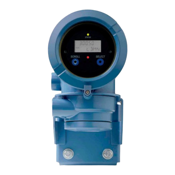
Transmitter operation Figure 7-1: Transmitter display features A. Status LED B. Display (LCD panel) C. Process variable D. Scroll optical switch E. Optical switch indicator: turns red when either Scroll or Select is activated F. Select optical switch G. Unit of measure for process variable H. -
Page 86: View Transmitter Status Using The Status Led
Transmitter operation • To view a more complete set of process variables, plus the current state of the outputs, choose Service Tools > Variables. View transmitter status using the status LED The status LED shows the current alert condition of the transmitter. The status LED is located on the face of the transmitter. -
Page 87: View And Acknowledge Status Alerts
Transmitter operation Table 7-1: Transmitter status reported by status LED (continued) LED state Description Recommendation Flashing red (if ena- One or more high-severity alerts are active A high-severity alert condition affects meas- bled) and have not been acknowledged. urement accuracy and output behavior. Re- solve the alert condition before continuing. - Page 88 Transmitter operation Figure 7-2: Using the display to view and acknowledge the status alerts Scroll and Select simultaneously for 4 seconds SEE ALARM Select Is ACK ALL enabled? ACK ALL Select Scroll EXIT Select Scroll Active/ unacknowledged alarms? Alarm code NO ALARM Scroll Select...
-
Page 89: View And Acknowledge Alerts Using Prolink Iii
Transmitter operation Postrequisites • To clear the following alerts, you must correct the problem, acknowledge the alert, then power-cycle the transmitter: A001, A002, A010, A011, A012, A013, A018, A019, A022, A023, A024, A025, A028, A029, A031. • For all other alerts: If the alert is inactive when it is acknowledged, it will be removed from the list. -
Page 90: View Alerts Using The Field Communicator
Transmitter operation If the alert is active when it is acknowledged, it will be removed from the list when the alert condition clears. Related information Alert data in transmitter memory 7.4.3 View alerts using the Field Communicator You can view a list containing all alerts that are active, or inactive but unacknowledged. •... -
Page 91: Alert Data In Transmitter Memory
Transmitter operation 7.4.5 Alert data in transmitter memory The transmitter maintains three sets of data for every alert that is posted. For each alert occurrence, the following three sets of data are maintained in transmitter memory: • Alert List • Alert Statistics •... -
Page 92: Start And Stop Totalizers And Inventories
Transmitter operation Start and stop totalizers and inventories Display Section 7.6.1. ProLink III Device Tools > Totalizer Control > Totalizer and Inventories > Start All Totals Device Tools > Totalizer Control > Totalizer and Inventories > Stop All Totals Field Communicator Service Tools > Variables > Totalizer Control > All Totalizers > Start Totalizers Service Tools >... -
Page 93: Reset Totalizers
Transmitter operation Exit displays beneath the current totalizer value. 4. Select. 5. Select again to confirm. 6. Scroll to EXIT. • To stop all totalizers and inventories using the display: 1. Scroll until the word TOTAL appears in the lower left corner of the display. Important Because all totalizers are started or stopped together, it does not matter which total you use. -
Page 94: Reset Totalizers Using The Display
Transmitter operation 7.7.1 Reset totalizers using the display Prerequisites • The Totalizer Reset display function must be enabled. • The totalizer that you want to reset must be configured as a display variable. For example: If you want to reset the mass totalizer, Mass Total must be configured as a display variable. -
Page 95: Reset Inventories
Transmitter operation Exit displays beneath the current totalizer value. 3. Scroll until Reset displays beneath the current totalizer value. 4. Select. Reset and Yes? alternately flash beneath the current totalizer value. 5. Select again to confirm. 6. Scroll to EXIT. 7. - Page 96 Transmitter operation Micro Motion Model 2700 Transmitters with FOUNDATION Fieldbus...
-
Page 97: Chapter 8 Measurement Support
Measurement support Measurement support Topics covered in this chapter: • Options for measurement support • Use Smart Meter Verification (SMV) • Zero the meter • Validate the meter • Perform a (standard) D1 and D2 density calibration • Perform temperature calibration Options for measurement support Micro Motion provides several measurement support procedures to help you evaluate and maintain your flowmeter's accuracy. -
Page 98: Smv Requirements
Measurement support 8.2.1 SMV requirements To use SMV, the transmitter must be paired with an enhanced core processor. Table 8‐1 for the minimum version of the transmitter, enhanced core processor, and communication tool needed to support SMV. (If you are going to perform SMV using the display, only the transmitter and enhanced core processor versions apply.) Table 8-1: Minimum SMV version... -
Page 99: Run Smv
Measurement support SMV has an output mode called Continuous Measurement that allows the transmitter to keep measuring while the test is in progress. If you choose to run the test in Last Measured Value or Fault modes instead, the transmitter outputs will be held constant for the two minute duration of the test. - Page 100 Measurement support Option Description Last Value During the test, all outputs will report the last measured value of their as- signed process variable. The test will run for approximately 140 seconds. While the test is in progress, dots traverse the display and test progress is shown. Postrequisites View the test results and take any appropriate actions.
- Page 101 Measurement support Enter any desired information on the Test Definition screen, and click Next. All information on this screen is optional. Choose the desired output behavior. Option Description Continue Measur- During the test, all outputs will continue to report their assigned process variable.
-
Page 102: View Test Data
Measurement support 8.2.4 View test data You can view the results of the current test. You can also view results from previous tests. Important You can view previous test results and see detailed test reports only if SMV is licensed. The transmitter stores the following information about the previous twenty SMV tests: •... - Page 103 Measurement support b. Scroll to Results Read and press Select. The runcount of the most recent test is displayed. c. To view data for this test, press Select, then press Scroll to scroll through test data. d. To select a different test, press Scroll, then press Select when the transmitter displays Results More?.
- Page 104 Measurement support View test result data using ProLink III Prerequisites You can view test result data only if your SMV is licensed and only for tests that were run on the PC you are currently using. Procedure Choose Device Tools > Diagnostics > Meter Verification and click Previous Test Results.
-
Page 105: Schedule Automatic Execution Of The Smv Test
Measurement support • If the meter passes the second test, the first result can be ignored. • If the meter fails the second test, the flow tubes may be damaged. Call customer support. Abort A problem occurred with the meter verification test (such as process instability) or you stopped the test manually. - Page 106 Measurement support Figure 8-5: SMV – Top-level menu Scroll and Select simultaneously for 4 seconds Scroll ENTER METER VERFY Select RUN VERFY RESULTS READ SCHEDULE VERFY EXIT Scroll Scroll Scroll Select Select Select Scroll Select Scroll to Schedule Verfy and press Select. To schedule a single test or the first test in recurring execution: a.
- Page 107 Measurement support SMV flowchart: Scheduling test execution using the display Figure 8-6: Scheduling SMV test execution using the display SCHEDULE VERFY Select Schedule set? SCHED IS OFF TURN OFF SCHED/YES? Scroll Scroll Select Schedule deleted HOURS LEFT Scroll Select xx HOURS Select SET NEXT SET RECUR...
-
Page 108: Zero The Meter
Measurement support To schedule recurring execution, specify a value for Hours Between Recurring Runs. To disable scheduled execution: • To disable execution of a single scheduled test, set Hours Until Next Run to 0. • To disable recurring execution, set Hours Between Recurring Runs to 0. •... -
Page 109: Validate The Meter
Measurement support If necessary, modify Zero Time. Zero Time controls the amount of time the transmitter takes to determine its zero-flow reference point. The default Zero Time is 20 seconds. For most applications, the default Zero Time is appropriate. Postrequisites Restore normal flow through the sensor by opening the valves. - Page 110 Measurement support If you plan to calculate the meter factor for volume flow, be aware that validating volume in the field may be expensive, and the procedure may be hazardous for some process fluids. Therefore, because volume is inversely proportional to density, an alternative to direct measurement is to calculate the meter factor for volume flow from the meter factor for density.
-
Page 111: Alternate Method For Calculating The Meter Factor For Volume Flow
Measurement support 8.4.1 Alternate method for calculating the meter factor for volume flow The alternate method for calculating the meter factor for volume flow is used to avoid the difficulties that may be associated with the standard method. This alternate method is based on the fact that volume is inversely proportional to density. It provides partial correction of the volume flow measurement by adjusting for the portion of the total offset that is caused by the density measurement offset. -
Page 112: Perform A D1 And D2 Density Calibration Using Prolink Iii
Measurement support Prerequisites • During density calibration, the sensor must be completely filled with the calibration fluid, and flow through the sensor must be at the lowest rate allowed by your application. This is usually accomplished by closing the shutoff valve downstream from the sensor, then filling the sensor with the appropriate fluid. -
Page 113: Perform A D1 And D2 Density Calibration Using An Enhanced Ff Host
Measurement support Postrequisites If you disabled LD Optimization before the calibration procedure, re-enable it. 8.5.2 Perform a D1 and D2 density calibration using an enhanced FF host Read the Prerequistes on page 104 if you have not already done so. See the following figure. -
Page 114: Perform Temperature Calibration
Measurement support Perform temperature calibration Temperature calibration establishes the relationship between the temperature of the calibration fluids and the signal produced by the sensor. Prerequisites The temperature calibration is a two-part procedure: temperature offset calibration and temperature slope calibration. The two parts must be performed without interruption, in the order shown. -
Page 115: Perform Temperature Calibration Using A Fieldbus Host
Measurement support Important Consult customer support before performing a temperature calibration. Under normal circumstances, the temperature circuit is stable and should not need an adjustment. 8.6.1 Perform temperature calibration using a fieldbus host Write the temperature units to be used for calibration to Calibration TB > CAL_TEMPERATURE_UNITS (OD Index 56). - Page 116 Measurement support Micro Motion Model 2700 Transmitters with FOUNDATION Fieldbus...
-
Page 117: Chapter 9 Troubleshooting
Troubleshooting Troubleshooting Topics covered in this chapter: • Status alerts, causes, and recommendations • Flow measurement problems • Density measurement problems • Temperature measurement problems • Check power supply wiring • Check grounding • Check for radio frequency interference (RFI) •... - Page 118 Troubleshooting Alert num- Alert title Possible cause Recommended actions A004 Temperature Over- The RTD resistance is out of range • Check your process conditions against range for the sensor. The tube RTD resist- the values reported by the device. ance is out of range for the sensor. •...
- Page 119 Troubleshooting Alert num- Alert title Possible cause Recommended actions A009 Transmitter Initializ- Transmitter is in power-up mode. • Allow the meter to complete its power- ing/Warming Up up sequence. The alert should clear au- tomatically. • If other alerts are present, resolve those alert conditions first.
- Page 120 Troubleshooting Alert num- Alert title Possible cause Recommended actions A013 Zero Calibration There was too much process insta- • Remove or reduce sources of electro- Failed: Unstable bility during the calibration proce- mechanical noise (e.g., pumps, vibra- dure. tion, pipe stress), cycle power to the meter, then retry the procedure.
- Page 121 Troubleshooting Alert num- Alert title Possible cause Recommended actions A021 Transmitter/Sensor/ The configured board type does not • Verify all of the characterization or cali- Software Mismatch match the physical board, or the bration parameters. See the sensor tag configured sensor type does not or the calibration sheet for your meter.
- Page 122 Troubleshooting Alert num- Alert title Possible cause Recommended actions A031 Low Power The transmitter is not receiving • Check the wiring between the transmit- enough power. ter and the core processor, then cycle power to the meter. This alert will not clear until you cy- •...
- Page 123 Troubleshooting Alert num- Alert title Possible cause Recommended actions A102 Drive Overrange The drive power (current/voltage) is • Check the drive gain and the pickoff at its maximum. voltage. • Check the wiring between the sensor and the transmitter. • Verify that internal wiring is secure and that there are no internal electrical problems.
-
Page 124: Flow Measurement Problems
Troubleshooting Alert num- Alert title Possible cause Recommended actions A131 Meter Verification in A meter verification test is in pro- • Allow the procedure to complete. Progress: Outputs to gress, with outputs set to Last Meas- Last Measured Value ured Value. A132 Sensor Simulation Sensor simulation is enabled. - Page 125 Troubleshooting Problem Possible causes Recommended actions Erratic non-zero flow • Leaking valve or seal • Verify that the sensor orientation is appro- rate at no-flow condi- • Two-phase flow priate for your application (refer to the tions • Plugged or coated sensor tube sensor installation manual).
-
Page 126: Density Measurement Problems
Troubleshooting Problem Possible causes Recommended actions Inaccurate flow rate • Wiring problem • Check the wiring between the sensor and or batch total • Inappropriate measurement unit the transmitter. • Incorrect flow calibration factor • Verify that the measurement units are con- •... -
Page 127: Temperature Measurement Problems
Troubleshooting Problem Possible causes Recommended actions Unusually high densi- • Plugged or coated sensor tube • Ensure that all of the calibration parame- ty reading • Incorrect density calibration factors ters have been entered correctly. See the • Incorrect temperature measurement sensor tag or the calibration sheet for your •... -
Page 128: Check Power Supply Wiring
Troubleshooting Check power supply wiring If the power supply wiring is damaged or improperly connected, the transmitter may not receive enough power to operate properly. Prerequisites • You will need the installation manual for your transmitter. • When using DC power, a minimum of 1.5 amps of startup current is required. •... -
Page 129: Check Grounding
Troubleshooting Check grounding A sensor and the transmitter must be grounded. Prerequisites You will need an: • Installation manual for your sensor • Installation manual for your transmitter (remote-mount installations only) Procedure Refer to the sensor and transmitter installation manuals for grounding requirements and instructions. -
Page 130: Check The Drive Gain
Troubleshooting Check the settings of Two-Phase Flow Low Limit, Two-Phase Flow High Limit, and Two-Phase Flow Timeout. You can reduce the occurrence of two-phase flow alerts by setting Two-Phase Flow Low Limit to a lower value, Two-Phase Flow High Limit to a higher value, or Two-Phase Flow Timeout to a higher value. -
Page 131: Collect Drive Gain Data
Troubleshooting Table 9-1: Possible causes and recommended actions for excessive (saturated) drive gain (continued) Possible cause Recommended actions Vibrating element Ensure that the vibrating element is free to vibrate. not free to vibrate Erratic drive gain Table 9-2: Possible causes and recommended actions for erratic drive gain Possible cause Recommended actions Foreign material... -
Page 132: Collect Pickoff Voltage Data
Troubleshooting Table 9-3: Possible causes and recommended actions for low pickoff voltage (continued) Possible cause Recommended actions The vibrating element is not vibrating • Check for plugging or deposition. • Ensure that the vibrating element is free to vi- brate (no mechanical binding). Moisture in the sensor electronics Eliminate the moisture in the sensor electronics. - Page 133 Troubleshooting Procedure Disconnect power to the transmitter. DANGER! If the transmitter is in a hazardous area, wait 5 minutes before continuing. Unplug the terminal blocks from the terminal board on the core processor. Using a digital multimeter (DMM), check the pickoff coils by placing the DMM leads on the unplugged terminal blocks for each terminal pair.
- Page 134 Troubleshooting With the DMM set to its highest range, there should be infinite resistance on each lead. If there is any resistance at all, there is a short to case. Test the resistance of junction box terminal pairs. a. Test the brown terminal against all other terminals except the red one. b.
-
Page 135: Appendix A Transducer Blocks And Views
Transducer blocks and views Appendix A Transducer blocks and views Topics covered in this appendix: • Descriptions of transducer block table entries • Measurement transducer blocks • Calibration transducer blocks • Diagnostics transducer blocks • Device information transducer blocks • Local display transducer blocks •... -
Page 136: Descriptions Of Transducer Block Table Entries
Transducer blocks and views Descriptions of transducer block table entries Use the following definitions for the transducer block details tables: Index of the FOUNDATION Fieldbus parameter in the object dictionary Name Name of the fieldbus parameter used in the code Description Provides a description of the parameter. -
Page 137: Measurement Transducer Blocks
Transducer blocks and views Table A-2: Access (continued) RW (Auto) Read/write, with the transducer block in Auto mode List of values The list of valid values to write to an enumerated parameter. This field is not applicable for read only parameters. Valid value ranges for variable type parameters are specified in the tables. - Page 138 Transducer blocks and views Table A-3: Measurement transducer block parameters view list (continued) View Index Name ST_REV TAG_DESC — — — — STRATEGY — — — ALERT_KEY — — — MODE_BLK — — BLOCK_ERR — — UPDATE_EVT — — — —...
- Page 139 Transducer blocks and views Table A-3: Measurement transducer block parameters view list (continued) View Index Name MFLOW_M_FACTOR — — — DENSITY_M_FACTOR — — — VOL_M_FACTOR — — — MASS_LOW_CUT — — — VOLUME_FLOW_LOW_CUTOFF — — — DENSITY_LOW_CUTOFF — — — FLOW_DIRECTION —...
-
Page 140: Standard Fieldbus Parameters For Measurement Transducer Blocks
Transducer blocks and views Table A-3: Measurement transducer block parameters view list (continued) View Index Name SNS_GSVflowBaseUnit — — — SNS_GSVflowBaseTime — — — SNS_GSVflowFactor — — — SNS_GSVflowText — — — SNS_GSVtotText — — — SNS_GSV_FlowCutoff — — — SNS_ResetGSVolTotal —... - Page 141 Transducer blocks and views Index and name Description List of values The user description of the intended block Any 32 characters application. TAG_DESC Msg type = STR Data type = OCTET STRING (32) Store = Static Access = RW (OOS) or RW (Auto) Available in Release 1.0 Used to identify grouping of blocks.
- Page 142 Transducer blocks and views Index and name Description List of values Occurs when a static parameter is changed — while a block mode is not in out of service UPDATE_EVT (OOS) mode, or when the mode changes from OOS mode and one or more static pa- rameters changed while the block was OOS.
-
Page 143: Process Variables For Measurement Transducer Blocks
Transducer blocks and views Index and name Description List of values Used for all config, H/W, connection failure 0 = No Error of system problems in the block. 18 = Calibration Error XD_ERROR 19 = Configuration Error Msg type = VAR 20 = Electronics Failure Data type = Unsigned8 (1) 21 = Sensor Failure... - Page 144 Transducer blocks and views Table A-4: Process variables for measurement transducer blocks (continued) Index and name Description List of values Base mass unit 1089 = g 1088 = kg MFLOW_SPECIAL_UNIT_ Msg type = ENUM 1092 = t BASE Data type = Unsigned16 (2) 1094 = lb Store = Static 1095 = STon...
- Page 145 Transducer blocks and views Table A-4: Process variables for measurement transducer blocks (continued) Index and name Description List of values Density unit 1097 = kg/m3 1100 = g/cm3 DENSITY_UNITS Msg type = ENUM 1103 = kg/L Data type = Unsigned16 (2) 1104 = g/ml Store = Static 1105 = g/L...
- Page 146 Transducer blocks and views Table A-4: Process variables for measurement transducer blocks (continued) Index and name Description List of values Standard or special volume flow 1347 = m3/s rate unit 1348 = m 3/min VOLUME_FLOW_UNITS 1349 = m3/h CDM (2.0 and Msg type = ENUM 1350 = m3/d above)
- Page 147 Transducer blocks and views Table A-4: Process variables for measurement transducer blocks (continued) Index and name Description List of values Special volume unit conversion fac- — VOL_SPECIAL_UNIT_CONV Msg type = VAR Data type = FLOAT (4) Store = Static Access = RW (OOS) Available in Release 1.0 Special volume unit string Any 8 characters...
- Page 148 Transducer blocks and views Table A-4: Process variables for measurement transducer blocks (continued) Index and name Description List of values Density internal damping in sec- — onds DENSITY_DAMPING Msg type = VAR Data type = FLOAT (4) Store = Static Access = RW (OOS) Available in Release 1.0 Mass rate factor...
- Page 149 Transducer blocks and views Table A-4: Process variables for measurement transducer blocks (continued) Index and name Description List of values Flow direction 0 = Forward Only 1 = Reverse Only FLOW_DIRECTION Msg type = ENUM 2 = Bi-Directional Data type = Unsigned16 (2) 3 = Absolute Value Store = Static 4 = Negate/Forward Only...
-
Page 150: Totalizers For Measurement Transducer Blocks
Transducer blocks and views Table A-4: Process variables for measurement transducer blocks (continued) Index and name Description List of values Low density limit of sensor in g/cc — LOW_DENSITY_LIMIT Msg type = VAR Data type = FLOAT (4) Store = Static Access = Read only Available in Release 1.0 Low volume flow limit of sensor... - Page 151 Transducer blocks and views Table A-5: Totalizers for measurement transducer blocks (continued) Index and name Description List of values Reset all totals Value part of DS-66 1 = Reset RESET_TOTALS Msg type = VAR Data type = DS-66 (2) Store = — Access = R/W in any mode Available in Release 1.0 Reset all inventories...
-
Page 152: Gas Process Variables For Measurement Tranducer Blocks
Transducer blocks and views Table A-5: Totalizers for measurement transducer blocks (continued) Index and name Description List of values Volume inventory — VOLUME_INVENTORY Msg type = VAR Data type = DS-65 (5) Store = Dynamic/20 Access = Read only Available in Release 1.0 Standard or special mass total and 1089 = g mass inventory unit... - Page 153 Transducer blocks and views Table A-6: Gas process variables for measurement transducer blocks (continued) Index and name Description List of values Reference volume gas total (not — valid when petroleum measure- GSV_Vol_Tot ment or concentration measure- ment is enabled) Msg type = VAR Data type = DS-65 (5) Store = Dynamic/20 Access = Read only...
- Page 154 Transducer blocks and views Table A-6: Gas process variables for measurement transducer blocks (continued) Index and name Description List of values Gas standard volume total and in- 1053 = SCF ventory engineering units 1521 = Nm3 SNS_GSV_TotalUnits 1526 = Sm3 Msg type = ENUM 1531 = NL Data type = Unsigned16 (2)
-
Page 155: Other Additions For Measurement Transducer Blocks
Transducer blocks and views Table A-6: Gas process variables for measurement transducer blocks (continued) Index and name Description List of values Gas standard volume low flow cut- Must be >= 0.0 SNS_GSV_FlowCutoff Msg type = VAR Data type = FLOAT (4) Store = Static Access = R/W OOS Available in Release 4.0... -
Page 156: Calibration Transducer Blocks
Transducer blocks and views Table A-7: Other additions for measurement transducer blocks (continued) Index and name Description List of values Indicates whether flow is moving in Value part of DS-66 the forward or reverse direction 0 = Forward or Zero Flow SNS_ActualFlowDirection 1 = Reverse Flow Msg type = VAR... -
Page 157: Mode_Blk
Transducer blocks and views View Index Name MODE_BLK — — BLOCK_ERR — — UPDATE_EVT — — — — BLOCK_ALM — — — — TRANSDUCER_DIRECTORY — — — — TRANSDUCER_TYPE TRANSDUCER_TYPE_VER XD_ERROR — — COLLECTION_DIRECTORY — — — — MASS_FLOW_GAIN — —... -
Page 158: Standard Fieldbus Parameters For Calibration Transducer Blocks
Transducer blocks and views View Index Name T_DENSITY_FQ_COEFF1 — — — T_DENSITY_FQ_COEFF2 — — — TEMP_LOW_CAL — — — TEMP_HIGH_CAL — — — TEMP_VALUE — — — TEMP_OFFSET — — — TEMP_SLOPE — — — PRESSURE_COMP — — PRESSURE_UNITS — —... - Page 159 Transducer blocks and views Index and name Description List of values The revision level of the static data associ- — ated with the function block. Incremented ST_REV with each write of static store. Msg type = VAR Data type = Unsigned16 (2) Store = Static Access = Read only Available in Release 1.0...
- Page 160 Transducer blocks and views Index and name Description List of values Occurs when a static parameter is changed — while a block mode is not in out of service UPDATE_EVT (OOS) mode, or when the mode changes from OOS mode and one or more static pa- rameters changed while the block was OOS.
-
Page 161: Calibration Transducer Blocks
Transducer blocks and views Index and name Description List of values Used for all config, H/W, connection failure 0 = No Error of system problems in the block. 18 = Calibration Error XD_ERROR 19 = Configuration Error Msg type = VAR 20 = Electronics Failure Data type = Unsigned8 (1) 21 = Sensor Failure... - Page 162 Transducer blocks and views Table A-8: Calibration transducer blocks (continued) Index and name Description List of values Standard deviation of auto zero — ZERO_STD_DEV Msg type = VAR Data type = FLOAT (4) Store = Static Access = Read only Available in Release 1.0 Present flow signal offset at zero —...
- Page 163 Transducer blocks and views Table A-8: Calibration transducer blocks (continued) Index and name Description List of values Perform fourth point calibration 0 = None 1 = Start Cal D4_DENSITY_CAL Msg type = METHOD Data type = Unsigned16 (2) Store = — Access = R/W (OOS) Available in Release 1.0 Density calibration constant 1...
- Page 164 Transducer blocks and views Table A-8: Calibration transducer blocks (continued) Index and name Description List of values Density 1 (g/cc) — Msg type = VAR Data type = FLOAT (4) Store = Static Access = R/W (OOS) Available in Release 1.0 Density 2 (g/cc) —...
- Page 165 Transducer blocks and views Table A-8: Calibration transducer blocks (continued) Index and name Description List of values T-Series: Flow FQ Coefficient (FFQ) — T_FLOW_FQ_COEFF Msg type = VAR Data type = FLOAT (4) Store = Static Access = R/W (OOS) Available in Release 1.0 T-Series: Density TG Coefficient —...
-
Page 166: Pressure Compensation For Calibration Transducer Blocks
Transducer blocks and views Table A-8: Calibration transducer blocks (continued) Index and name Description List of values Temperature value for tempera- — ture calibrations (in degC) TEMP_VALUE Msg type = VAR Data type = FLOAT (4) Store = Static Access = R/W (OOS) Available in Release 1.0 Temperature calibration offset —... - Page 167 Transducer blocks and views Table A-9: Pressure compensation for calibration transducer blocks (continued) Index and name Description List of values Pressure unit 1148 = inH2O (68°F) 1724 = InH2O@60°F PRESSURE_UNITS Msg type = ENUM 1156 = inHg (0°C) Data type = Unsigned16 (2) 1154 = ftH2O (68°F) Store = Static 1151 = mmH2O (68°F)
-
Page 168: Temperature Compensation For Calibration Transducer Blocks
Transducer blocks and views A.3.5 Temperature compensation for calibration transducer blocks Table A-10: Temperature compensation for calibration transducer blocks Index and name Description List of values Enable/Disable temperature com- 0 = disabled pensation 1 = enabled SNS_ PuckEnableExtTemp Msg type = METHOD Data type = Unsigned16 (2) Store = Static Access = R/W (OOS) -
Page 169: Diagnostics Transducer Blocks
Transducer blocks and views Table A-11: Other additions for calibration transducer blocks (continued) Index and name Description List of values Pressure input type 1 = Digital Comm 2 = Fixed PRESSURE_INPUT_TYPE Msg type = VAR Data type = Unsigned16 (2) Store = Static Access = R/W (OOS) Available in Release 9.0... - Page 170 Transducer blocks and views View Index Name SLUG_LOW_LIMIT — — — — — SLUG_HIGH_LIMIT — — — — — ALARM1_STATUS — — — — ALARM2_STATUS — — — — ALARM3_STATUS — — — — ALARM4_STATUS — — — — FAULT_LIMIT —...
- Page 171 Transducer blocks and views View Index Name MFP_TYPE — — — — — MFP_TV_INST — — — — — MFP_TV_INST — — — — — MFP_TV_STD_DEV — — — — — MFP_TV_MAX — — — — — MFP_TV_MIN — — —...
- Page 172 Transducer blocks and views View Index Name FRF_StiffnessRpo_ — — — — — stddev FRF_Damping_stddev — — — — — FRF_MassLpo_stddev — — — — — FRF_MassRpo_stddev — — — — — FRF_StiffnessLpo_air — — — — — FRF_StiffnessRpo_air — —...
- Page 173 Transducer blocks and views View Index Name FRF_MV_Elapse_Time — — — — — FRF_MV_Time_Left — — — — — FRF_ToneLevel — — — — — FRF_ToneRampTime — — — — — FRF_BlCoeff — — — — — FRF_DriveTarget — — —...
-
Page 174: Standard Fieldbus Parameters For Diagnostic Transducer Blocks
Transducer blocks and views A.4.2 Standard fieldbus parameters for diagnostic transducer blocks Index and name Description List of values The beginning of the transducer block. — BLOCK_STRUCTURE Msg type = VAR Data type = DS_64 (5) Store = Static Access = RW (OOS) or RW (Auto) Available in Release 1.0 The revision level of the static data associ- —... - Page 175 Transducer blocks and views Index and name Description List of values The actual, target, permitted, and normal See section 2.6 of FF-891 modes of the block. MODE_BLK Msg type = REC Data type = DS-69 (4) Store = Mixed Access = RW (OOS) or RW (Auto) Available in Release 1.0 The error status associated with the hard- See section 4.8 of FF-903...
-
Page 176: Slug Flow Setup For Diagnostic Transducer Blocks
Transducer blocks and views Index and name Description List of values Identifies the version of the transducer — block. Format is XXYY where XX is the ma- TRANSDUCER_ jor spec revision and YY is the manufacturer TYPE_VER revision. Msg type = VAR Data type = Unsigned16 (2) Store = Static Access = RW (OOS) -
Page 177: Alarm Status For Diagnostic Transducer Blocks
Transducer blocks and views Table A-12: Slug flow setup for diagnostic transducer blocks (continued) Index and name Description List of values High density limit in g/cc — SLUG_HIGH_LIMIT Msg type = VAR Data type = FLOAT (4) Store = Static Access = R/W in any mode Available in Release 1.0 A.4.4... - Page 178 Transducer blocks and views Table A-13: Alarm status for diagnostic transducer blocks (continued) Index and name Description List of values Status Word 2 0x0001 = Line RTD Over 0x0002 = Meter RTD Over ALARM2_STATUS Msg type = ENUM 0x0004 = CP Exception Data type = BIT STRING (2) 0x0008 = API: Temp OOL Store = Dynamic/20...
- Page 179 Transducer blocks and views Table A-13: Alarm status for diagnostic transducer blocks (continued) Index and name Description List of values Status Word 4 0x0001 = Cal Fail: Low 0x0002 = Cal Fail: High ALARM4_STATUS Msg type = ENUM 0x0004 = Cal Fail: Noisy Data type = BIT STRING (2) 0x0008 = Auto Zero IP Store = Dynamic/20...
- Page 180 Transducer blocks and views Table A-13: Alarm status for diagnostic transducer blocks (continued) Index and name Description List of values Alarm index 0 = No Alarm 1 = A001 - (E)EPROM Error (CP) ALARM_INDEX Msg type = ENUM 2 = A002 - RAM Error (CP) Data type = Unsigned16 (2) 3 = A003 - Sensor Failure Store = Static...
- Page 181 Transducer blocks and views Table A-13: Alarm status for diagnostic transducer blocks (continued) Index and name Description List of values Failed 35 = A035 - Meter Verification Aborted 36 = A036 - Viscosity Out of Lim- 37 = A037 - Sensor Check Failed 38 = A038 - Time Period Out of Range 42 = A102 - Drive Overrange/Par-...
-
Page 182: Device Diagnostics From Diagnostics Transducer Block
Transducer blocks and views A.4.5 Device diagnostics from diagnostics transducer block Table A-14: Device diagnostics from diagnostics transducer block List of Index and name Description values Drive gain — DRIVE_GAIN Msg type = VAR Data type = DS-65 (5) Store = Dynamic/20 Access = Read only Available in Release 1.0 Raw tube period... - Page 183 Transducer blocks and views Table A-14: Device diagnostics from diagnostics transducer block (continued) List of Index and name Description values Maximum electronics temperature — ELECT_TEMP_ Msg type = VAR Data type = FLOAT (4) Store = Dynamic/20 Access = Read only Available in Release 2.0 Minimum electronics temperature —...
-
Page 184: Meter Fingerprinting For Diagnostic Transducer Blocks
Transducer blocks and views Table A-14: Device diagnostics from diagnostics transducer block (continued) List of Index and name Description values Meter RTD resistance in ohms — RTD_RESISTANCE_ Msg type = VAR METER Data type = FLOAT (4) Store = Dynamic/20 Access = Read only Available in Release 3.0 Number of core processor power cycles... - Page 185 Transducer blocks and views Table A-15: Meter fingerprinting for diagnostic transducer blocks (continued) Index and name Description List of values Meter fingerprint in SI (0) or English 0x0000 = SI (1) units 0x0001 = English MFP_UNITS Msg type = ENUM Data type = Unsigned16 (2) Store = Static Access = R/W in any mode...
-
Page 186: Other Additions For Diagnostics Transducer Blocks
Transducer blocks and views Table A-15: Meter fingerprinting for diagnostic transducer blocks (continued) Index and name Description List of values Transmitter variable, maximum — (since last statistics reset) MFP_TV_MAX Msg type = VAR Data type = FLOAT (4) Store = Dynamic Access = Read only Available in Release 3.0 Transmitter variable, minimum... - Page 187 Transducer blocks and views Table A-16: Other additions for diagnostics transducer blocks (continued) Index and name Description List of values Actual target amplitude (mV/Hz) — (pre 700 2.1, actual & override) SNS_TargetAmplitude Msg type = VAR Data type = FLOAT (4) Store = Dynamic Access = Read only Available in Release 4.0...
- Page 188 Transducer blocks and views Table A-16: Other additions for diagnostics transducer blocks (continued) Index and name Description List of values Start/Stop meter verification - (ap- 0= Disabled plicable only if meter verification is 1 = Fixed output mode FRF_EnableFCFValidation enabled) 2 = Factory air verification 3 = Factory water verification Msg type = METHOD...
- Page 189 Transducer blocks and views Table A-16: Other additions for diagnostics transducer blocks (continued) Index and name Description List of values The reason the meter verification 0 = No error routine aborted 1 = Manual abort FRF_AbortCode 2 = Watchdog timeout Msg type = ENUM 3 = Frequency drift Data type = Unsigned16 (2)
- Page 190 Transducer blocks and views Table A-16: Other additions for diagnostics transducer blocks (continued) Index and name Description List of values The current RPO stiffness calcula- — ted as a mean FRF_StiffnessRpo_mean Msg type = VAR Data type = FLOAT (4) Store = Static Access = Read only Available in Release 4.0...
- Page 191 Transducer blocks and views Table A-16: Other additions for diagnostics transducer blocks (continued) Index and name Description List of values The current damping calculated as — a standard deviation FRF_Damping_stddev Msg type = VAR Data type = FLOAT (4) Store = Static Access = Read only Available in Release 4.0 The current LPO mass calculated as...
- Page 192 Transducer blocks and views Table A-16: Other additions for diagnostics transducer blocks (continued) Index and name Description List of values The LPO mass calculated as a mean — during Factory Cal of Air FRF_MassLpo_air Msg type = VAR Data type = FLOAT (4) Store = Static Access = Read only Available in Release 4.0...
- Page 193 Transducer blocks and views Table A-16: Other additions for diagnostics transducer blocks (continued) Index and name Description List of values The RPO mass calculated as a mean — during Factory Cal of Water FRF_MassRpo_water Msg type = VAR Data type = FLOAT (4) Store = Static Access = Read only Available in Release 4.0...
- Page 194 Transducer blocks and views Table A-16: Other additions for diagnostics transducer blocks (continued) Index and name Description List of values FCF Datalog Item 2: Status; Abort Bit 7 = FCF pass/fail states are compressed to fit into 3 Bits 6-4 = state FRF_MV_Status bits Bits 3-0 = abort code...
- Page 195 Transducer blocks and views Table A-16: Other additions for diagnostics transducer blocks (continued) Index and name Description List of values #100 Temperature — FRF_Temp Msg type = VAR Data type = FLOAT (4) Store = Static Access = Read only Available in Release 6.0 #101 Density...
- Page 196 Transducer blocks and views Table A-16: Other additions for diagnostics transducer blocks (continued) Index and name Description List of values #106 FCF timers: time until first run in — hours (applicable only if meter veri- FRF_MV_FirstRun_Time fication feature is enabled) Msg type = VAR Data type = FLOAT (4) Store = Static...
- Page 197 Transducer blocks and views Table A-16: Other additions for diagnostics transducer blocks (continued) Index and name Description List of values #111 BL coefficient (applicable only if — meter verification feature is ena- FRF_BlCoeff bled) Msg type = VAR Data type = FLOAT (4) Store = Static Access = R/W (OOS) Available in Release 7.0...
- Page 198 Transducer blocks and views Table A-16: Other additions for diagnostics transducer blocks (continued) Index and name Description List of values #116 Maximum sensor current (applica- — ble only if meter verification feature FRF_Max_Current_mA is enabled) Msg type = VAR Data type = FLOAT (4) Store = Static Access = R/W (OOS) Available in Release 7.0...
- Page 199 Transducer blocks and views Table A-16: Other additions for diagnostics transducer blocks (continued) Index and name Description List of values #121 Temperature unit 1000 = K 1001 = Deg C DIAG_TEMPERATURE_ Msg type = ENUM 1002 = Deg F UNITS Data type = Unsigned16 (2) 1003 = Deg R Store = Static...
-
Page 200: Device Information Transducer Blocks
Transducer blocks and views Table A-16: Other additions for diagnostics transducer blocks (continued) Index and name Description List of values #126 Indexed by R2984 — DIAG_FRF_RPO_METER_ Msg type = VAR FACTOR Data type = FLOAT (4) Store = Static Access = Read only Available in Release 8.0 #127 Indexed by R2984... - Page 201 Transducer blocks and views View Index Name STRATEGY — — — ALERT_KEY — — — MODE_BLK — — BLOCK_ERR — — UPDATE_EVT — — — — BLOCK_ALM — — — — TRANSDUCER_DIRECTORY — — — — TRANSDUCER_TYPE TRANSDUCER_TYPE_VER XD_ERROR — —...
-
Page 202: Standard Fieldbus Parameters For Device Information Transducer Blocks
Transducer blocks and views A.5.2 Standard fieldbus parameters for device information transducer blocks Index and name Description List of values The beginning of the transducer block. — BLOCK_STRUCTURE Msg type = VAR Data type = DS_64 (5) Store = Static Access = RW (OOS) or RW (Auto) Available in Release 1.0 The revision level of the static data associ-... - Page 203 Transducer blocks and views Index and name Description List of values The actual, target, permitted, and normal See section 2.6 of FF-891 modes of the block. MODE_BLK Msg type = REC Data type = DS-69 (4) Store = Mixed Access = RW (OOS) or RW (Auto) Available in Release 1.0 The error status associated with the hard- See section 4.8 of FF-903...
-
Page 204: Transmitter Data For Device Information Transducer Blocks
Transducer blocks and views Index and name Description List of values Identifies the version of the transducer — block. Format is XXYY where XX is the ma- TRANSDUCER_ jor spec revision and YY is the manufacturer TYPE_VER revision. Msg type = VAR Data type = Unsigned16 (2) Store = Static Access = RW (OOS) -
Page 205: Sensor Data For Device Information Transducer Blocks
Transducer blocks and views Table A-17: Transmitter data for device information transducer blocks (continued) Index and name Description List of values Model 700 transmitter software re- — vision 700_SW_REV Msg type = VAR Data type = Unsigned16 (2) Store = Static Access = Read only Available in Release 1.0 Model 2700 transmitter software... - Page 206 Transducer blocks and views Table A-18: Sensor data for device information transducer blocks (continued) Index and name Description List of values Sensor type (i.e. F200, CMF025) — SENSOR_TYPE Msg type = STR Data type = VISIBLE STRING (16) Store = Static Access = Read only Available in Release 1.0 Sensor type code...
- Page 207 Transducer blocks and views Table A-18: Sensor data for device information transducer blocks (continued) Index and name Description List of values Flange type 0 = ANSI 150 [CP, ECP, FDM, FVM] SENSOR_END Msg type = ENUM 1 = ANSI 300 Data type = Unsigned16 (2) 2 = ANSI 600 Store = Static...
- Page 208 Transducer blocks and views Table A-18: Sensor data for device information transducer blocks (continued) Index and name Description List of values Device type for the attached core 40 = 700 [CP] processor 50 = 800 [ECP] SNS_PuckDeviceTypeCode 61 = Density Msg type = ENUM Data type = Unsigned16 (2) Store = Static...
-
Page 209: Local Display Transducer Blocks
Transducer blocks and views Local display transducer blocks A.6.1 View list for local display transducer block The following table lists the parameters contained in the transducer block for local display parameters. Four views are defined for the local display transducer block. The table also shows the applicable views for each parameter, and the size of the parameter in that view, in bytes. -
Page 210: Standard Fieldbus Parameters For Local Display Transducer Blocks
Transducer blocks and views View Index Name LDO_VAR_3_CODE — — — LDO_VAR_4_CODE — — — LDO_VAR_5_CODE — — — LDO_VAR_6_CODE — — — LDO_VAR_7_CODE — — — LDO_VAR_8_CODE — — — LDO_VAR_9_CODE — — — LDO_VAR_10_CODE — — — LDO_VAR_11_CODE —... - Page 211 Transducer blocks and views Index and name Description List of values The revision level of the static data associ- — ated with the function block. Incremented ST_REV with each write of static store. Msg type = VAR Data type = Unsigned16 (2) Store = Static Access = Read only Available in Release 1.0...
- Page 212 Transducer blocks and views Index and name Description List of values Occurs when a static parameter is changed — while a block mode is not in out of service UPDATE_EVT (OOS) mode, or when the mode changes from OOS mode and one or more static pa- rameters changed while the block was OOS.
-
Page 213: Local Display Transducer Blocks
Transducer blocks and views Index and name Description List of values Used for all config, H/W, connection failure 0 = No Error of system problems in the block. 18 = Calibration Error XD_ERROR 19 = Configuration Error Msg type = VAR 20 = Electronics Failure Data type = Unsigned8 (1) 21 = Sensor Failure... - Page 214 Transducer blocks and views Table A-19: Local display transducer blocks (continued) Index and name Description List of values Enable/Disable LDO offline menu fea- 0 = Disable ture 1 = Enable EN_LDO_OFFLINE_MENU Msg type = ENUM Data type = Unsigned16 (2) Store = Static Access = R/W in any mode Available in Release 1.0...
- Page 215 Transducer blocks and views Table A-19: Local display transducer blocks (continued) Index and name Description List of values Display the language selection 0 = English 1 = German UI_Language Msg type = ENUM 2 = French Data type = Unsigned16 (2) 3 = Reserved Store = Static 4 = Spanish...
- Page 216 Transducer blocks and views Table A-19: Local display transducer blocks (continued) Index and name Description List of values #25 LDO_VAR_1_CODE Displays the variable associated with 0 = Mass Flow Rate [700, 800] #26 LDO_VAR_2_CODE the code on the LDO 1 = Temperature #27 LDO_VAR_3_CODE 2 = Mass Total [700, 800] Msg type = ENUM...
- Page 217 Transducer blocks and views Table A-19: Local display transducer blocks (continued) Index and name Description List of values 63 = Gas Std Vol Total [700, 800] 64 = Gat Std Vol Inventory [700, 800] 69 = Live Zero [700, 800] 159 = User Defined Equation [CDM, FDM, FVM] 161 = Tube-Case Temperature...
-
Page 218: Petroleum Measurement Transducer Blocks
Transducer blocks and views Table A-19: Local display transducer blocks (continued) Index and name Description List of values Enable/Disable display status LED 0 = Disable blinking 1 = Enable UI_EnableStatusLedBlinking Msg type = ENUM Data type = Unsigned16 (2) Store = Static Access = R/W in any mode Available in Release 4.0 Enable/Disable display alarm screen... - Page 219 Transducer blocks and views View Index Name BLOCK_STRUCTURE — — — — ST_REV TAG_DESC — — — — STRATEGY — — — ALERT_KEY — — — MODE_BLK — — BLOCK_ERR — — UPDATE_EVT — — — — BLOCK_ALM — — —...
-
Page 220: Standard Fieldbus Parameters For Petroleum Measurement Transducer Blocks
Transducer blocks and views A.7.2 Standard fieldbus parameters for petroleum measurement transducer blocks Index and name Description List of values The beginning of the transducer block. — BLOCK_STRUCTURE Msg type = VAR Data type = DS_64 (5) Store = Static Access = RW (OOS) or RW (Auto) Available in Release 1.0 The revision level of the static data associ-... - Page 221 Transducer blocks and views Index and name Description List of values The actual, target, permitted, and normal See section 2.6 of FF-891 modes of the block. MODE_BLK Msg type = REC Data type = DS-69 (4) Store = Mixed Access = RW (OOS) or RW (Auto) Available in Release 1.0 The error status associated with the hard- See section 4.8 of FF-903...
-
Page 222: Process Variables For Petroleum Measurement Transducer Blocks
Transducer blocks and views Index and name Description List of values Identifies the version of the transducer — block. Format is XXYY where XX is the ma- TRANSDUCER_ jor spec revision and YY is the manufacturer TYPE_VER revision. Msg type = VAR Data type = Unsigned16 (2) Store = Static Access = RW (OOS) - Page 223 Transducer blocks and views Table A-20: Process variables for petroleum measurement transducer blocks (continued) Index and name Description List of values Batch weighted average density — API_Ave_Corr_Density Msg type = VAR Data type = DS-65 (5) Store = Dynamic/20 Access = Read only Available in Release 3.0 Batch weighted average tempera- —...
-
Page 224: Setup Data For Petroleum Measurement Transducer Blocks
Transducer blocks and views A.7.4 Setup data for petroleum measurement transducer blocks Table A-21: Setup data for petroleum measurement transducer blocks Index and name Description List of values Enable/Disable petroleum measure- 0 = disabled ment 1 = enabled EN_API Msg type = ENUM Data type = Unsigned16 (2) Store = Static Access = Read only... - Page 225 Transducer blocks and views Table A-21: Setup data for petroleum measurement transducer blocks (continued) Index and name Description List of values Reset PM/GSV inventory 0 = No effect 1 = Reset SNS_ResetAPIGSVInv Msg type = METHOD Data type = Unsigned16 (2) Store = Static Access = R/W in any mode Available in Release 4.0...
- Page 226 Transducer blocks and views Table A-21: Setup data for petroleum measurement transducer blocks (continued) Index and name Description List of values Standard or special volume flow rate 1347 = m3/s unit 1348 = m 3/min API_VOL_FLOW_UNITS 1349 = m3/h Msg type = ENUM 1350 = m3/d Data type = Unsigned16 (2) 1351 = L/s...
-
Page 227: Concentration Measurement Transducer Blocks
Transducer blocks and views Table A-21: Setup data for petroleum measurement transducer blocks (continued) Index and name Description List of values Pressure units 1148 = inH2O (68°F) 1724 = InH2O@60°F API_PressureUnit Msg type = ENUM 1156 = inHg (0°C) Data type = Unsigned16 (2) 1154 = ftH2O (68°F) Store = Static 1151 = mmH2O (68°F) - Page 228 Transducer blocks and views View Index Name BLOCK_STRUCTURE — — — — ST_REV TAG_DESC — — — — STRATEGY — — — ALERT_KEY — — — MODE_BLK — — BLOCK_ERR — — UPDATE_EVT — — — — BLOCK_ALM — — —...
- Page 229 Transducer blocks and views View Index Name ED_Temp_Index — — — ED_Conc_Index — — — ED_Temp_ISO — — — ED_Dens_At_Temp_ISO — — — ED_Dens_At_Temp_Coeff — — — ED_Conc_Label_55 — — — ED_Dens_At_Conc — — — ED_Dens_At_Conc_Coeff — — — ED_Conc_Label_51 —...
-
Page 230: Standard Fieldbus Parameters For Concentration Measurement Transducer Blocks
Transducer blocks and views View Index Name ED_SYS_AttachedCoreType — — — SNS_ED_ConcUnits_SpecialUnit — — — ED_MASSFLOW_UNITS — — — ED_VOL_TOT_UNITS — — — ED_MASS_TOT_UNITS — — — A.8.2 Standard fieldbus parameters for concentration measurement transducer blocks Index and name Description List of values The beginning of the transducer block. - Page 231 Transducer blocks and views Index and name Description List of values The identification number of the plant unit. 1 to 255 This information may be used in the host ALERT_KEY for sorting alarms, etc. Msg type = VAR Data type = Unsigned8 (1) Store = Static Access = RW (OOS) or RW (Auto) Available in Release 1.0...
- Page 232 Transducer blocks and views Index and name Description List of values A directory that specifies the number and — starting indices of the data collections in TRANSDUCER_ the transducer block. DIRECTORY Msg type = VAR Data type = Unsigned16 (2) Store = Static Access = RW (OOS) Available in Release 9.0...
-
Page 233: Process Variables For Concentration Measurement Transducer Blocks
Transducer blocks and views A.8.3 Process variables for concentration measurement transducer blocks Table A-22: Process variables for concentration measurement transducer blocks Index and name Description List of values Density at reference — ED_Ref_Dens Msg type = VAR Data type = DS-65 (5) Store = Dynamic/20 Access = Read only Available in Release 3.0... -
Page 234: Totals For Concentration Measurement Transducer Blocks
Transducer blocks and views Table A-22: Process variables for concentration measurement transducer blocks (continued) Index and name Description List of values Density (fixed baume units) — ED_Baume Msg type = VAR Data type = DS-65 (5) Store = Dynamic/20 Access = Read only Available in Release 3.0 A.8.4 Totals for concentration measurement transducer... -
Page 235: Setup Data For Concentration Measurement Transducer Blocks
Transducer blocks and views Table A-23: Totals for concentration measurement transducer blocks (continued) Index and name Description List of values Net volume inventory — ED_Net_Vol_Inv Msg type = VAR Data type = DS-65 (5) Store = Dynamic/20 Access = Read only Available in Release 3.0 Reset concentration measurement Value part of DS-66... - Page 236 Transducer blocks and views Table A-24: Setup data for concentration measurement transducer blocks (continued) Index and name Description List of values Lock enhanced density tables 0 = not locked 1 = locked ED_Curve_Lock Msg type = ENUM Data type = Unsigned16 (2) Store = Static Access = R/W (OOS) Available in Release 3.0...
- Page 237 Transducer blocks and views Table A-24: Setup data for concentration measurement transducer blocks (continued) Index and name Description List of values Curve (6x5) temperature iso- — therm value (x-axis) ED_Temp_ISO Msg type = VAR Data type = FLOAT (4) Store = Static Access = R/W (OOS) Available in Release 3.0 Curve...
- Page 238 Transducer blocks and views Table A-24: Setup data for concentration measurement transducer blocks (continued) Index and name Description List of values Curve (5x1) concentration value — (y-axis) ED_Conc_Label_51 Msg type = VAR Data type = FLOAT (4) Store = Static Access = R/W (OOS) Available in Release 3.0 Curve...
- Page 239 Transducer blocks and views Table A-24: Setup data for concentration measurement transducer blocks (continued) Index and name Description List of values Curve ASCII string – name of curve — – 12 characters supported ED_Curve_Name Msg type = VAR Data type = VISIBLE STRING (12) Store = Static Access = R/W in any mode Available in Release 3.0...
-
Page 240: Other Additions For Concentration Measurement Transducer Blocks
Transducer blocks and views A.8.6 Other additions for concentration measurement transducer blocks Table A-25: Other additions for concentration measurement transducer blocks Index and name Description List of values Reset concentration measurement 0 = No effect volume inventory 1 = Reset SNS_ResetEDVolInv Msg type = METHOD Data type = Unsigned16 (2) - Page 241 Transducer blocks and views Table A-25: Other additions for concentration measurement transducer blocks (continued) Index and name Description List of values Enable high density extrapolation 1 = Enable alarm SNS_ED_EnableDensHighEx- trap Msg type = ENUM Data type = Unsigned16 (2) Store = Static Access = R/W in any mode Available in Release 4.0...
- Page 242 Transducer blocks and views Table A-25: Other additions for concentration measurement transducer blocks (continued) Index and name Description List of values Standard or special volume flow rate 1347 = m3/s unit 1348 = m 3/min ED_VOL_FLOW_UNITS 1349 = m3/hr Msg type = ENUM 1350 = m3/day Data type = Unsigned16 (2) 1351 = L/s...
- Page 243 Transducer blocks and views Table A-25: Other additions for concentration measurement transducer blocks (continued) Index and name Description List of values Enable concentration measurement 0 = disabled curve auto-switching 1 = enabled DEN_Enable_CMAutoswitch Msg type = VAR Data type = Unsigned16 (2) Store = —...
-
Page 244: Density Viscosity Meter Transducer Blocks
Transducer blocks and views Table A-25: Other additions for concentration measurement transducer blocks (continued) Index and name Description List of values Volume flow total unit 1034 = m3 1036 = cm3 ED_VOL_TOT_UNITS Msg type = ENUM 1038 = L Data type = Unsigned16 (2) 1043 = ft3 Store = Dynamic 1048 = gallon... - Page 245 Transducer blocks and views View Index Name TRANSDUCER_ — — — — — — — — DIRECTORY TRANSDUCER_TYPE — — — — TRANSDUCER_TYPE_ — — — — XD_ERROR — — — — — — COLLECTION_ — — — — — —...
- Page 246 Transducer blocks and views View Index Name DEN_KV5 — — — — — — — DEN_KV6 — — — — — — — DEN_CalibrationStatus — — — — — — — DEN_KV_Index — — — — — — — DEN_KV_Crossover —...
- Page 247 Transducer blocks and views View Index Name DEN_Programmable- — — — — — — — ConstF DEN_Programmable- — — — — — — — ValA DEN_Programmable- — — — — — — — ValB DEN_Programmable- — — — — — —...
- Page 248 Transducer blocks and views View Index Name DEN_KinematicViscosi- — — — — — — — tyUnits VISC_RANGE_SEL_IN- — — — — — — — DEN_V0 — — — — — — — DEN_V1 — — — — — — — DEN_V2 —...
- Page 249 Transducer blocks and views View Index Name MBUS_Visc_CurveIn- — — — — — — — MBUS_Visc_TempIn- — — — — — — — DEN_RefVisc_Mat_ — — — — — — — MaxFitOrder EN_RefVisc_Mat_Tem- — — — — — — — pISO DEN_RefVisc_Mat_Vis- —...
- Page 250 Transducer blocks and views View Index Name DEN_CaseTemperatur- — — — — — — — eStability DEN_SpecialEquation- — — — — — — — Type DEN_Legacy_K0 — — — — — — — DEN_Legacy_K1 — — — — — — —...
-
Page 251: Standard Fieldbus Parameters For Density Viscosity Meter Transducer Blocks
Transducer blocks and views View Index Name PRESSURE_UNITS — — — — — — — DEN_ProductCode — — — — — — — — Velocity_Switch_Sta- — — — — — — — DEN_RefWaterDensity — — — — — — — DEN_RefTemperature —... - Page 252 Transducer blocks and views Index and name Description List of values The user description of the intended block Any 32 characters application. TAG_DESC Msg type = STR Data type = OCTET STRING (32) Store = Static Access = RW (OOS) or RW (Auto) Available in Release 1.0 Used to identify grouping of blocks.
- Page 253 Transducer blocks and views Index and name Description List of values Occurs when a static parameter is changed — while a block mode is not in out of service UPDATE_EVT (OOS) mode, or when the mode changes from OOS mode and one or more static pa- rameters changed while the block was OOS.
-
Page 254: Process Variables For Density Viscosity Transducer Blocks
Transducer blocks and views Index and name Description List of values Used for all config, H/W, connection failure 0 = No Error of system problems in the block. 18 = Calibration Error XD_ERROR 19 = Configuration Error Msg type = VAR 20 = Electronics Failure Data type = Unsigned8 (1) 21 = Sensor Failure... - Page 255 Transducer blocks and views Table A-26: Process variables for density viscosity transducer blocks (continued) Index and name Description List of values Curve configuration index (n) 1 = Use user sensor check value DEN_UseUserSensorCheck Msg type = VAR 0 = Use factory sensor Value Data type = Unsigned16 (2) check value...
- Page 256 Transducer blocks and views Table A-26: Process variables for density viscosity transducer blocks (continued) Index and name Description List of values Densisty scale factor — DensityScaleFactor Msg type = VAR Data type = Unsigned16 (2) Store = Static Access = R/W (OOS) Available in Release 8.0 Temperature scale factor —...
- Page 257 Transducer blocks and views Table A-26: Process variables for density viscosity transducer blocks (continued) Index and name Description List of values K2, instrument calibration factor — DEN_K2 Msg type = VAR Data type = Float (4) Store = Static Access = R/W (OOS) Available in Release 8.0 K18, instrument calibration factor —...
- Page 258 Transducer blocks and views Table A-26: Process variables for density viscosity transducer blocks (continued) Index and name Description List of values KV calibration factor index (0-1) 0: Medium 1: High DEN_KV_Index Msg type = ENUM (1) Data type = Unsigned8 (1) Store = Static Access = R/W in any mode Available in Release 8.0...
- Page 259 Transducer blocks and views Table A-26: Process variables for density viscosity transducer blocks (continued) Index and name Description List of values A6, density calibration constant — DEN_A6 Msg type = VAR Data type = Float (4) Store = Static Access = R/W (OOS) Available in Release 8.0 A7, density calibration constant —...
- Page 260 Transducer blocks and views Table A-26: Process variables for density viscosity transducer blocks (continued) Index and name Description List of values Fixed flow velocity value (m/sec) — DEN_FixedVelocity Msg type = VAR Data type = DS65 Store = Dynamic/20 Access = Read only Available in Release 8.0 Flow velocity units 1061 = Meters/Sec-...
- Page 261 Transducer blocks and views Table A-26: Process variables for density viscosity transducer blocks (continued) Index and name Description List of values Time period (u/sec) (upper 3dB point) — DEN_TimePeriodB Msg type = VAR Data type = Float (4) Store = Dynamic/20 Access = Read only Available in Release 8.0 Time period (u/sec) (lower 3dB point)
-
Page 262: Den_Programmable
Transducer blocks and views Table A-26: Process variables for density viscosity transducer blocks (continued) Index and name Description List of values Programmable constant E for special — equation (Y for special equation type I) DEN_ProgrammableConstE Msg type = VAR Data type = Float (4) Store = Static Access = R/W (OOS) Available in Release 8.0... -
Page 263: Den_Programmable
Transducer blocks and views Table A-26: Process variables for density viscosity transducer blocks (continued) Index and name Description List of values Programmable constant D for special — equation - constants available for access DEN_ProgrammableValD using pointers for special equations (reg- isters 4114-4119) Msg type = VAR Data type = Float (4) -
Page 264: Den_Specialeqnslota
Transducer blocks and views Table A-26: Process variables for density viscosity transducer blocks (continued) Index and name Description List of values Pointer A for special equation 1 = Temperature 3 = Density DEN_SpecialEqnSlotA Msg type = ENUM 5 = Volume Flow Rate Data type = Unsigned16 (2) [CDM] Store = Static... -
Page 265: Den_Specialeqnslotb
Transducer blocks and views Table A-26: Process variables for density viscosity transducer blocks (continued) Index and name Description List of values Pointer B for special equation See #74 DEN_Special- EqnSlotA DEN_SpecialEqnSlotB Msg type = ENUM Data type = Unsigned16 (2) Store = Static Access = R/W (OOS) Available in Release 8.0... -
Page 266: Den_Qualityfactor
Transducer blocks and views Table A-26: Process variables for density viscosity transducer blocks (continued) Index and name Description List of values Special equation unit string — DEN_SpecialEqnLabel Msg type = STR Data type = VISIBLE STRING Store = Static Access = R/W (OOS) Available in Release 8.0 Special density unit string —... -
Page 267: Den_Dynamicviscosity
Transducer blocks and views Table A-26: Process variables for density viscosity transducer blocks (continued) Index and name Description List of values Dynamic viscosity — DEN_DynamicViscosity Msg type = VAR Data type = DS65 Store = Dynamic Access = Read only Available in Release 8.0 Kinematic viscosity —... - Page 268 Transducer blocks and views Table A-26: Process variables for density viscosity transducer blocks (continued) Index and name Description List of values V2 at the selected range - Array of 4 — DEN_V2 Msg type = VAR Data type = Float (4) Store = Static Access = R/W (OOS) Available in Release 8.0...
- Page 269 Transducer blocks and views Table A-26: Process variables for density viscosity transducer blocks (continued) Index and name Description List of values #102 Special kinematic viscosity unit string Visible string DEN_KinViscSpecialUnitLabel Msg type = STR Data type = VISIBLE STRING Store = Static Access = R/W (OOS) Available in Release 8.0 #103...
- Page 270 Transducer blocks and views Table A-26: Process variables for density viscosity transducer blocks (continued) Index and name Description List of values #109 Average time period on air/vacuum (in- — dexed by DEN_KDV_CalIndex) DEN_AverageTimePeriod Msg type = VAR Data type = Float (4) Store = Static Access = Read only Available in Release 8.0...
- Page 271 Transducer blocks and views Table A-26: Process variables for density viscosity transducer blocks (continued) Index and name Description List of values #114 Referred viscosity calculation method 0 = referral matrix 1 = ASTM D341 single DEN_ReferredViscMethod Msg type = ENUM curve Data type = Unsigned16 (2) 2 = ASTM D341 multi-...
- Page 272 Transducer blocks and views Table A-26: Process variables for density viscosity transducer blocks (continued) Index and name Description List of values #119 Referred viscosity (6x6) @ temperature — isothermX, curve (indexed by MBUS_ DEN_RefVisc_Mat_ Visc_CurveIndex and MBUS_Visc_Tem- ViscAtTempISO pIndex) Msg type = VAR Data type = Float (4) Store = Static Access = R/W (OOS)
- Page 273 Transducer blocks and views Table A-26: Process variables for density viscosity transducer blocks (continued) Index and name Description List of values #125 Number of ASTM reference curves (n = — 2-8) DEN_RefVisc_ASTM_NumCurves Msg type = VAR Data type = Unsigned16 (2) Store = Static Access = R/W (OOS) Available in Release 8.0...
- Page 274 Transducer blocks and views Table A-26: Process variables for density viscosity transducer blocks (continued) Index and name Description List of values #130 Lab viscosity for viscosity scaling factor — calibration DEN_LabViscosity Msg type = VAR Data type = Float (4) Store = Static Access = R/W (OOS) Available in Release 8.0...
- Page 275 Transducer blocks and views Table A-26: Process variables for density viscosity transducer blocks (continued) Index and name Description List of values #137 Case temperature stability (sensor check) — DEN_CaseTemperatureStability Msg type = VAR Data type = Float (4) Store = Static Access = Read only Available in Release 8.0 #138...
- Page 276 Transducer blocks and views Table A-26: Process variables for density viscosity transducer blocks (continued) Index and name Description List of values #144 K20A constant used to compute K20 (in- — dexed by DEN_Legacy_K20_K21_Index) DEN_Legacy_K20A Msg type = VAR Data type = Float (4) Store = Static Access = R/W (OOS) Available in Release 8.0...
- Page 277 Transducer blocks and views Table A-26: Process variables for density viscosity transducer blocks (continued) Index and name Description List of values #150 Time period A (in microseconds) — DEN_TPA_Microsec Msg type = VAR Data type = DS65 Store = Dynamic Access = Read only Available in Release 8.0 #151...
- Page 278 Transducer blocks and views Table A-26: Process variables for density viscosity transducer blocks (continued) Index and name Description List of values #157 Index for KDV results 0 = Factory 1 = User DEN_KDV_CalIndex Msg type = VAR Data type = Unsigned16 (2) Store = Static Access = R/W (OOS) Available in Release 8.0...
- Page 279 Transducer blocks and views Table A-26: Process variables for density viscosity transducer blocks (continued) Index and name Description List of values #163 Secondary referred viscosity — DEN_SecBaseViscosity Msg type = VAR Data type = DS65 Store = Dynamic Access = Read only Available in Release 8.0 #164 Unit for reference and secondary refer-...
- Page 280 Transducer blocks and views Table A-26: Process variables for density viscosity transducer blocks (continued) Index and name Description List of values #167 Pressure unit 1148 = inch water @ 68F / inch water@60F PRESSURE_UNITS Msg type = ENUM 1156 = inch HG @ 0C Data type = Unsigned16 (2) 1154 = ft water @ 68F Store = Dynamic...
- Page 281 Transducer blocks and views Table A-26: Process variables for density viscosity transducer blocks (continued) Index and name Description List of values #171 Reference temperature for inline calibra- — tion DEN_RefTemperature Msg type = VAR Data type = Float (4) Store = Static Access = R/W in any mode Available in Release 9.0 #172...
- Page 282 Transducer blocks and views (1) The list within the square bracket contains cores that support this value. Micro Motion Model 2700 Transmitters with FOUNDATION Fieldbus...
-
Page 283: Appendix B Fieldbus Channel References
Fieldbus channel references Appendix B Fieldbus channel references Table B-1: Analog input function blocks Channel number Channel description Valid unit code Core applicability Mass Flow Measurement TB > Mass Flow Units Temperature Measurement TB > Temperature Units Density Measurement TB > Density Units Volume Flow Measurement TB >... - Page 284 Fieldbus channel references Table B-1: Analog input function blocks (continued) Channel number Channel description Valid unit code Core applicability ED Specific Gravity Measurement TB > Density Units ED Std Vol Flow Measurement TB > Volume Flow Units ED Net Mass Flow Measurement TB >...
- Page 285 Fieldbus channel references Table B-3: Discrete input function blocks (continued) Channel number Channel description Core applicability SNS ZeroInProgress SYS AnalogOutputFault SNS MVFailed Table B-4: Discrete output function blocks Channel number Channel description Core applicability Start Sensor Zero Reset Mass Total Reset Volume Total Reset API Reference (Standard) Volume Total Reset All Process Totals (not Inv)
- Page 286 Fieldbus channel references Table B-5: AI function blocks Channel number Channel description Valid unit code Core applicability Special Equation Output 1588 = No Units Time Period A 1057 - Micro Second Time Period B 1057 - Micro Second Tube-case temperature differential Measurement TB >...
-
Page 287: Foundation
™ FOUNDATION fieldbus function blocks Appendix C ™ FOUNDATION fieldbus function blocks Topics covered in this appendix: • Analog Input (AI) function block • Analog Output (AO) function block • Integrator (INT) Function Block • Discrete Input (DI) function block •... -
Page 288: Ai Block Modes
™ FOUNDATION fieldbus function blocks • OUT_SCALE: The high and low scale values, engineering units code, and number of digits to the right of the decimal point associated with OUT when L_TYPE is not direct. • SIMULATE: A group of data that contains the current transducer value and status, the simulated transducer value and status, and the enable/disable bit. - Page 289 ™ FOUNDATION fieldbus function blocks CHANNEL Select the channel that corresponds to the desired sensor measurement. The following table provides a list of AI Function block channel numbers and channel applicability depending upon attached core type to transmitter. If a channel is not supported for the given core type, the channel value will not work for the transmitter.
- Page 290 ™ FOUNDATION fieldbus function blocks Table C-1: AI block channel definitions (continued) Channel Description Flow velocity (1) This channel assignment is supported only by CDM software revision 2.0 and above. L_TYPE The L_TYPE parameter defines the relationship of the sensor measurement to the desired output of the AI block.
-
Page 291: Ai Block Filtering
™ FOUNDATION fieldbus function blocks C.1.5 AI block filtering The filtering feature changes the response time of the device to smooth variations in output readings caused by rapid changes in input. Adjust the filter time constant (in seconds) using the PV_FTIME parameter. Set the filter time constant to zero to disable the filter feature. -
Page 292: Ai Block Status Handling
™ FOUNDATION fieldbus function blocks Number Description The priority of an alarm condition changes to 0 after the condition that caused the alarm is corrected. An alarm condition with a priority of 1 is recognized by the system, but is not reported to the operator. -
Page 293: Analog Output (Ao) Function Block
™ FOUNDATION fieldbus function blocks AI1 (AI_2600_ AI2 (AI_2800_ AI3 (AI3000_ AI4 (AI_3200_ xxxx) xxxx) xxxx) xxxx Channel Mass flow (1) Temperature (2) Density (3) Volume flow (4) OUT_SCALE EU_100 EU_0 Unit_Index Decimal L_TYPE Direct Direct Direct Direct Analog Output (AO) function block The AO block converts the FF value to a channel value by using two sets of scaling values. -
Page 294: Ao Block Modes
™ FOUNDATION fieldbus function blocks • PV_SCALE: PV_SCALE is used to convert the FF value in SP to percent. The units are usually percent. • XD_SCALE: XD_SCALE is used to convert the percent FF value to the value for the channel, which should be given in the device manual. -
Page 295: Ao Block Simulation
™ FOUNDATION fieldbus function blocks C.2.4 AO block simulation When simulation is enabled, the last value of OUT is maintained and reflected in the field value of the SIMULATE attribute. In this case, the PV and READBACK values and statuses are based on the SIMULATE value and the status that you enter. -
Page 296: Integrator (Int) Function Block
™ FOUNDATION fieldbus function blocks Integrator (INT) Function Block The Integrator (INT) function block integrates one or two variables over time. The block compares the integrated or accumulated value to pre-trip and trip limits and generates discrete output signals when the limits are reached. The INT integrates one process value. -
Page 297: Int Block Configuration Parameters
™ FOUNDATION fieldbus function blocks This block is intended to have measurements that come from a process calculation path. It will work with input from a control path. The block output starts a process calculation path. The block is unusual because the status of the output has to be calculated. The output status is not directly related to the status of the inputs. -
Page 298: Int Block Other Parameters
If the Confirm reset is set, the block shall not process subsequent re- set at RESET_IN until RESET_CONFIRM discrete input is TRUE. Input 1 pass through This is special option only used for Emerson Integrator block to pass internal totals to Integrator block. •... -
Page 299: Int Block Modes
™ FOUNDATION fieldbus function blocks • SRTOTAL: The read-only snapshot of RTOTAL just before a reset. Same units as OUT. • N_RESET: Counts the number of resets. It can not be written or reset. C.3.3 INT block modes The Integrator function block supports the following modes: •... -
Page 300: Int Block Special Mode
™ FOUNDATION fieldbus function blocks C.3.6 INT block special mode Enhanced FF host Overview > Totalizer Control > Configure Integrator Block Fieldbus Host Measurement TB > INTEGRATOR_FB_CONFIG (OD Index 50) Along with standard operation of integrating the process value at INn, the Micro Motion Integrator function block has one special mode of operation: Input 1 pass through. -
Page 301: Int Block Default Configuration
™ FOUNDATION fieldbus function blocks Fieldbus code Label Description Internal ED: Net Block outputs internal ED: net mass total value and RESET_IN re- Mass Total sets internal ED: net mass total Internal ED: Net Block outputs internal ED: net mass inventory value and RESET_IN Mass Inventory resets internal ED: net mass inventory Internal ED: Net... -
Page 302: Di Block Modes
™ FOUNDATION fieldbus function blocks Channel Description Zero in progress Analog output fault Meter verification failed • IO_OPTS: allows the option to have the value of FIELD_VAL_D be logically inverted before becoming the PV_D, if the “Invert” option is selected. •... -
Page 303: Di Block Default Configuration
™ FOUNDATION fieldbus function blocks C.4.6 DI block default configuration DI1 (DI_4400_xxxx) CHANNEL Analog Output Fault (33) IO_OPTS 0x0000 STATUS_OPTS 0x0000 Discrete Output (DO) function block The Discrete Output (DO) function block processes a discrete setpoint and saves it to a specified channel to produce an output signal. -
Page 304: Do Block Modes
™ FOUNDATION fieldbus function blocks • IO_OPTS: Options which the user may select to alter input and output block processing. Invert - Causes the SP_D value to be inverted before it becomes the output. May be used for normally open solenoid valves and other inverted actuators. SP-PV Track in Man - The value of SP is set to the value of PV when the target mode is Man. -
Page 305: Do Block Errors
™ FOUNDATION fieldbus function blocks C.5.3 DO block errors The following conditions are reported in the BLOCK_ERR attribute: • Simulate Active: SIMULATE_D is enabled; therefore, PV_D is not real. • Input failure/process variable has Bad status: The readback value is bad. •... - Page 306 ™ FOUNDATION fieldbus function blocks Micro Motion Model 2700 Transmitters with FOUNDATION Fieldbus...
-
Page 307: Appendix D Using The Transmitter Display
Using the transmitter display Appendix D Using the transmitter display Using the display D.1.1 Components of the transmitter interface The transmitter interface includes the status LED, the display (LCD panel), and two optical switches. Figure D-1: Transmitter interface Status LED Display (LCD panel) Process variable Scroll optical switch... -
Page 308: Use The Optical Switches
Using the transmitter display Note Display refers to the display on the remotely mounted transmitter, not directly mounted to the meter. If there is a display directly on the meter, it can only view process variables, and it cannot be used for any other operation. - Page 309 Using the transmitter display Prerequisites To access the display menu system, operator access to either the Off-Line menu or the Alert menu must be enabled. To access the complete menu system, operator access must be enabled for both the Off-Line menu and the Alert menu. Procedure At the transmitter display, activate theScroll and Select optical switches simultaneously until the display changes.
- Page 310 Using the transmitter display • Exit each menu separately, working your way back to the top of the menu system. • Wait until the display times out and returns to displaying process variable data. Enter a floating-point value using the display Certain configuration values (for example, Lower Range Value and Upper Range Value) are entered as floating-point values.
- Page 311 Using the transmitter display If the current value is positive and there is a blank space at the left of the value, activate Select until the cursor is flashing under the blank space, then activate Scroll until the minus sign appears. If the current value is positive and there is no blank space at the left of the value, activate Select until the cursor is flashing under the leftmost digit, then activate Scroll until the minus sign appears.
- Page 312 Using the transmitter display • S = Sign. A minus sign (−) indicates a negative number. A blank indicates a positive number. • X.XXX = The 4-digit mantissa. • E = The exponent indicator. • YY = The 2-digit exponent. Procedure Switch from decimal notation to exponential notation.
-
Page 313: Display Codes For Process Variables
Using the transmitter display To save the displayed value to transmitter memory, activate Scroll and Select simultaneously and hold until the display changes. • If the displayed value is the same as the value in transmitter memory, you will be returned to the previous screen. -
Page 314: Codes And Abbreviations Used In Display Menus
Using the transmitter display Table D-2: Display codes for process variables (continued) Code Definition Comment or reference STD V Standard volume flow rate Concentration measurement application only STDVI Standard volume inventory Concentration measurement application only TCDENS Temperature-corrected density Petroleum measurement application only TCORI Temperature-corrected inventory Petroleum measurement application only... - Page 315 Using the transmitter display Table D-3: Codes and abbreviations used in display menus (continued) Code or abbrevia- tion Definition Comment or reference CUSTODY XFER Custody transfer DENS Density D EV Discrete event Events configured using the enhanced event model DGAIN, DRIVE % Drive gain DISBL Disable...
- Page 316 Using the transmitter display Table D-3: Codes and abbreviations used in display menus (continued) Code or abbrevia- tion Definition Comment or reference INTERN Internal Input/output LANG Language LOCK Write-protect LOOP CUR Loop current M_ASC Modbus ASCII M_RTU Modbus RTU MAO1 mA Output 1 (primary mA Output) MAO2...
- Page 317 Using the transmitter display Table D-3: Codes and abbreviations used in display menus (continued) Code or abbrevia- tion Definition Comment or reference WRPRO Write protect PVR applications only XMTR Transmitter Configuration and Use Manual...
- Page 318 Using the transmitter display Micro Motion Model 2700 Transmitters with FOUNDATION Fieldbus...
-
Page 319: Appendix E Using Prolink Iii With The Transmitter
In most ProLink III installations, the manual is installed with the ProLink III program. Additionally, the ProLink III manual is available on the documentation CD or at www.emerson.com. ProLink III features and functions ProLink III offers complete transmitter configuration and operation functions. ProLink III also offers a number of additional features and functions, including: •... - Page 320 Using ProLink III with the transmitter ProLink III messages As you use ProLink III with a Micro Motion transmitter, you will see a number of messages and notes. This manual does not document all of these messages and notes. Important The user is responsible for responding to messages and notes and complying with all safety messages.
-
Page 321: Appendix F Using A Field Communicator With The Transmitter
If you are unable to perform these tasks, consult the Field Communicator manual before attempting to use the Field Communicator. The Field Communicator manual is available on the documentation CD or at www.emerson.com. Field Communicator menus and messages Many of the menus in this manual start with the On-Line menu. Ensure that you are able to navigate to the On-Line menu. -
Page 322: Connect With The Ff Host
Using a Field Communicator with the transmitter Connect with the FF host A connection from the FOUNDATION Fieldbus host to your transmitter allows you to read process data, configure the transmitter, and perform maintenance and troubleshooting tasks. Procedure Micro Motion Model 2700 Transmitters with FOUNDATION Fieldbus... -
Page 323: Appendix G Default Values And Ranges
Default values and ranges Appendix G Default values and ranges Default values and ranges The default values and ranges represent the typical factory transmitter configuration. Depending on how the transmitter was ordered, certain values may have been configured at the factory and are not represented in the default values and ranges. Table G-1: Transmitter default values and ranges Type... - Page 324 Default values and ranges Table G-1: Transmitter default values and ranges (continued) Type Parameter Default Range Comments Density units g/cm Density cutoff 0.2 g/cm 0.0 – 0.5 g/cm 0 g/cm 1 g/cm 1000 µsec 1000 – 50,000 µsec 50,000 µsec 1000 –...
- Page 325 Default values and ranges Table G-1: Transmitter default values and ranges (continued) Type Parameter Default Range Comments External pressure 0.000 psi Mass flow rate 200.000 g/s Volume flow rate 0.200 L/s Density 10.000 g/cm Temperature 450.000 °C Drive gain 100.000% Gas standard volume flow rate 423.78 SCFM External temperature...
- Page 326 Default values and ranges Micro Motion Model 2700 Transmitters with FOUNDATION Fieldbus...
-
Page 327: Appendix H Transmitter Components And Installation Wiring
Transmitter components and installation wiring Appendix H Transmitter components and installation wiring Topics covered in this appendix: • Installation types • Power supply terminals and ground • Fieldbus wiring terminals Installation types The transmitter was ordered and shipped to be installed in one of several possible configurations. - Page 328 Transmitter components and installation wiring Figure H-2: High-temperature meters with factory connection The transmitter is shipped with a flexible connection factory installed between the sensor and the transmitter. The transmitter must be dismounted from its shipping location (spot‐welded to the sensor case) and then mounted separately.
- Page 329 Transmitter components and installation wiring Figure H-4: 4-wire remote installation for density and viscosity meters (CDM, FDM, or FVM with fieldbus only) The transmitter is installed remotely from the Compact Density Meter (CDM), Fork Density Meter (FDM), or Fork Viscosity Meter (FVM). The 4‐wire connection between the sensor and transmitter must be field wired. Power supply must be field wired to the transmitter.
- Page 330 Transmitter components and installation wiring Figure H-5: 9-wire remote installation The transmitter and core processor are combined in a single unit that is installed remotely from the sensor. The 9‐wire connection between the transmitter/core processor and the sensor must be field wired. Power supply must be field wired to the transmitter.
- Page 331 Transmitter components and installation wiring Figure H-6: Remote core processor with remote sensor installation The transmitter, core processor, and sensor are all mounted separately. The 4‐wire connection between the transmitter and core processor must be field wired. The 9‐wire connection between the core processor and the sensor must be field wired.
-
Page 332: Power Supply Terminals And Ground
Transmitter components and installation wiring Power supply terminals and ground Figure H-7: Power supply wiring terminals Warning flap Equipment ground Power supply wiring terminals (9 and 10) Fieldbus wiring terminals FOUNDATION Fieldbus Micro Motion Model 2700 Transmitters with FOUNDATION Fieldbus... -
Page 333: Appendix Ine53 History
NE53 history Appendix I NE53 history This document can be found at www.emerson.com. Operating instructions within this document are English versions. Instructions in other languages have different part numbers but matching revision letters. Operating Date Version Type Change instruction 09/2000... - Page 334 NE53 history Operating Date Version Type Change instruction Expansion • Software version information available either through the display or through Modbus • Totalizers can be disabled, in addition to starting and stopping • Doubled the number of virtual communication rela- tionshups (VCRs) Adjustment •...
- Page 335 NE53 history Operating Date Version Type Change instruction 07/2012 Adjustment • Added DI channels to increment the Concentration 3600326 EB Mass Curve • Added Special units support for both Mass Flow and Volume Flow • Moved mass flow, volume flow, and density limit pa- rameters from the Device Info TB to the Measurement •...
- Page 336 NE53 history Micro Motion Model 2700 Transmitters with FOUNDATION Fieldbus...
- Page 337 NE53 history Configuration and Use Manual...
- Page 338 © 2018 Micro Motion, Inc. All rights reserved. The Emerson logo is a trademark and service mark of Emerson Electric Co. Micro Motion, ELITE, ProLink, MVD and MVD Direct Connect marks are marks of one of the Emerson Automation Solutions family of companies. All other marks are property of their respective owners.
Need help?
Do you have a question about the Micro Motion 2700 and is the answer not in the manual?
Questions and answers