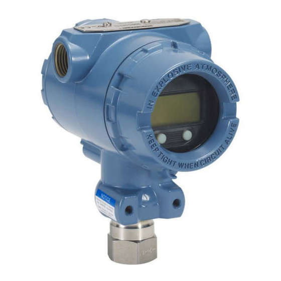
Emerson Rosemount 2051 Reference Manual
Pressure transmitter with hart revision 5 and 7 selectable protocol
Hide thumbs
Also See for Rosemount 2051:
- Reference manual (228 pages) ,
- Quick start manual (48 pages) ,
- Quick installation manual (25 pages)

Related Manuals for Emerson Rosemount 2051


Summary of Contents for Emerson Rosemount 2051
- Page 1 Reference Manual 00809-0100-4107, Rev CC February 2024 Rosemount ™ 2051 Pressure Transmitter with HART Revision 5 and 7 Selectable Protocol ®...
- Page 2 Do not attempt to loosen or remove flange bolts while the transmitter is in service. WARNING Replacement equipment or spare parts not approved by Emerson for use as spare parts could reduce the pressure retaining capabilities of the transmitter and may render the instrument dangerous.
- Page 3 Severe changes in the electrical loop may inhibit HART communication or the ability to reach alarm values. ® Therefore, Emerson cannot absolutely warrant or guarantee that the correct failure alarm level ( HIGH can be read by the host system at the time of annunciation.
-
Page 5: Table Of Contents
5.4 Determine calibration frequency.................... 84 5.5 Compensating for span line pressure effects (Range 4 and 5)........... 86 5.6 Trimming the pressure signal....................87 5.7 Trimming the analog output....................90 ® 5.8 Switching HART revision......................93 Chapter 6 Troubleshooting........................97 6.1 Overview.............................97 6.2 Troubleshooting for 4-20 mA output..................97 Emerson.com... - Page 6 B.1 Communication device menu trees..................119 B.2 Communication device fast keys..................123 Appendix C Local operator interface (LOI) menu.................. 125 C.1 Local operator interface (LOI) menu tree................125 C.2 Local operator interface (LOI) menu tree - extended menu..........126 C.3 Enter numbers.........................127 C.4 Text entry..........................128 Rosemount 2051...
-
Page 7: Chapter 1 Introduction
Reference Manual Introduction 00809-0100-4107 February 2024 1 Introduction 1.1 Models covered The following Rosemount 2051 Transmitters are covered by this manual: • Rosemount 2051C Coplanar Pressure Transmitter ™ • Rosemount 2051T In-Line Pressure Transmitter — Measures gauge/absolute pressure up to 10,000 psi (689.5 bar). -
Page 8: Hart ® Installation Flowchart
Introduction Reference Manual February 2024 00809-0100-4107 1.2 HART installation flowchart ® Figure 1-1: HART installation flowchart Rosemount 2051... -
Page 9: Transmitter Overview
The display indicates output and abbreviated diagnostic messages. Emerson provides a glass display cover. For 4-20 mA HART output, the LCD display features a two-line display. The first line displays the actual measured value, and the second line of six characters displays the engineering units. -
Page 10: Product Recycling/Disposal
• Engineering units • Communication I. Memory • Configuration J. Digital-to-analog signal conversion K. Digital communication L. Communication device 1.4 Product recycling/disposal Consider recycling equipment and packaging and dispose of them in accordance with local and national legislation/regulations. Rosemount 2051... -
Page 11: Chapter 2 Configuration
5. In the Choose a Communication Protocol drop-down list, select HART 6. In the Choose a Brand drop-down list, select Rosemount 7. Select the desired DD (listed by product name and HART revision). ® 8. Select the SOFTWARE VERSION, HOST SYSTEM, and DEVICE MANAGER. 9. Click DOWNLOAD. Emerson.com... -
Page 12: Configuration Basics
Device descriptor file names use Device and DD Revision, such as 10_01. HART protocol is designed to enable legacy device descriptor revisions to continue to communicate with new HART devices. To access new functionality, download the new DD. Emerson recommends downloading new DD files to ensure full functionality. - Page 13 Dashboard interfaces. This section describes all steps using a communication device using Dashboard interfaces. HART shows the Device Dashboard interface. It is critical that the latest device descriptors ® (DDs) are loaded into the communication device. Refer to either Software & Drivers FieldCommGroup.org to download latest DD library. Emerson.com...
- Page 14 When using the LOI for configuration, several features require multiple screens for a successful configuration. Data entered will be saved on a screen-by-screen basis; the LOI will indicate this by flashing on the LCD display each SAVED time. Rosemount 2051...
- Page 15 The prompt is only a reminder; acknowledging this prompt does not set the loop to manual. It is necessary to set the loop to manual control as a separate operation. Emerson.com...
-
Page 16: Verifying Configuration
Reference Manual February 2024 00809-0100-4107 2.4 Verifying configuration Emerson recommends verifying various configuration parameters prior to installation into the process. This section details the various parameters for each configuration tool. Depending on what configuration tool(s) are available, follow the steps listed. 2.4.1 ... -
Page 17: Basic Setup Of The Transmitter
2, 2, 1, 1, 4 Set pressure units using AMS Device Manager Procedure 1. Right-click the device and select Configure. 2. Select Manual Setup and select desired units from the Pressure Units drop-down menu. 3. Select Send when complete. Emerson.com... - Page 18 2. Use the SCROLL and ENTER buttons to select the desired unit. 3. Save by selecting SAVE as indicated on the LCD display screen. 2.5.2 Setting transmitter output (transfer function) The Rosemount 2051 Transmitter has two transfer functions for pressure applications: Linear and Square Root. As shown in Figure 1, activating the Square Root option makes the transmitter analog output proportional to flow.
- Page 19 100 percent of range. In practice, the transmitter range values may be changed as often as necessary to reflect changing process requirements. Select from one of the methods below to rerange the transmitter. Each method is unique; examine all options closely before deciding which method works best for your process. Emerson.com...
- Page 20 Reranging using an applied pressure source is a way of reranging the transmitter without entering specific 4 and 20 mA (1–5 Vdc) points. Rerange with an applied pressure source using a communication device Procedure From the HOME screen, enter the fast key sequence: Fast keys 2, 2, 2, 2 Rosemount 2051...
- Page 21 Zero and Span button location. Figure 2-10: Analog Zero and Span buttons A. Zero and Span buttons Procedure 1. Loosen the screw holding the top tag of the transmitter housing. Rotate the label to expose the Zero and Span buttons. Emerson.com...
- Page 22 1. Right-click the device and select Configure. 2. Select Manual Setup. 3. Within the Pressure Setup box, enter desired damping value and click Send. 4. Carefully click the warning and click Yes if it is safe to apply the changes. Rosemount 2051...
-
Page 23: Configuring The Lcd Display
From the HOME screen, enter the fast key sequence: 2, 2, 4 Fast keys 2.6.2 Configure LCD display using AMS Device Manager Procedure 1. Right-click the device and select Configure. 2. Click Manual Setup and select the Display tab. 3. Select desired display options and select Send. Emerson.com... -
Page 24: Detailed Transmitter Setup
AMS Device Manager, or the local operator interface (LOI). The following limitations exist for custom levels: • Low alarm level must be less than the low saturation level • High alarm level must be higher than the high saturation level Rosemount 2051... - Page 25 BACK TO MENU BACK TO MENU EXIT MENU EXIT MENU 2.7.2 Configuring scaled variable With the scaled variable configuration, you can create a relationship/conversion between the pressure units and user-defined/custom units. There are two use cases for a scaled Emerson.com...
- Page 26 Point at which output is driven to zero to prevent problems cause by Low flow cutoff process noise. Emerson highly recommends using the low flow cut off function in order to have a stable output and avoid problems due to process noise at a low flow or no flow condition.
- Page 27 Use a differential transmitter in a level application. Once installed on an empty tank with the taps vented, the process variable reading is -209.4 inH O. The process variable reading is the head pressure created by fill fluid in the capillary. Based on Table 2-7, the scaled variable configuration would be as follows: Emerson.com...
- Page 28 In this particular application, the flow rate at full scale flow is 20,000 gallons of water per hour. Emerson highly recommends using the Low flow cutoff function in order to have a stable output and avoid problems due to process noise at a low flow or no flow condition.
-
Page 29: Performing Transmitter Tests
Configuring alarm and saturation levels Verifying configuration parameters 2.8.2 Performing an analog loop test The analog loop test command verifies the output of the transmitter, the integrity of the loop, and the operations of any recorders or similar devices installed in the loop. Emerson.com... - Page 30 Reference Manual February 2024 00809-0100-4107 Emerson recommends testing the 4-20 mA (1-5 Vdc) points in addition to alarm levels when installing, repairing, or replacing a transmitter. The host system may provide a current measurement for the 4–20 mA (1-5 Vdc) HART ®...
-
Page 31: Configuring Burst Mode
AMS Device Manager, or a control system to initiate a request. 2.9.1 Selecting Burst mode options in HART ® The message content options are: • PV (primary variable) only • Percent of range • PV, 2V, 3V, 4V • Process variables • Device status Emerson.com... -
Page 32: Establishing Multidrop Communication
You can establish communication with transmitters using HART modems and a ® host implementing HART protocol. Each transmitter is identified by a unique address and responds to the commands defined in the HART protocol. Communication devices and AMS Rosemount 2051... - Page 33 A. HART modem B. Power supply Emerson sets the product to address zero (0) at the factory, which allows operation in the standard point-to-point manner with a 4–20 mA (1–5 Vdc) output signal. To activate multidrop communication, change the transmitter address to a number from 1 to 15 for HART Revision 5, or 1–63 for HART Revision 7.
- Page 34 To set up a communication device for polling: Procedure 1. Go to Utility → Configure HART Application. 2. Select Polling Addresses. 3. Enter 0-63 Communicate with a multidropped transmitter using AMS Device Manager Procedure Select the HART modem icon and select Scan All Devices. ® Rosemount 2051...
-
Page 35: Chapter 3 Hardware Installation
February 2024 3 Hardware installation 3.1 Overview The information in this section covers installation considerations for the Rosemount 2051 with HART protocols. ® Emerson ships a Quick Start Guide with every transmitter to describe recommended pipe- fitting and wiring procedures for initial installation. -
Page 36: Installation Procedures
Most transmitters are calibrated in the horizontal position. Mounting the transmitter in any other position will shift the zero point to the equivalent amount of liquid head pressure caused by the varied mounting position. Related information Trimming the pressure signal Rosemount 2051... - Page 37 ™ installed with four 1.75-inch flange bolts. Stainless steel bolts supplied by Emerson are coated with a lubricant to ease installation. Carbon steel bolts do not require lubrication. Do not apply any additional lubricant when Emerson.com...
- Page 38 Hardware installation Reference Manual February 2024 00809-0100-4107 installing either type of bolt. Bolts supplied by Emerson are identified by their head markings. Related information Install bolts Install bolts NOTICE The use of non-approved bolts could reduce pressure. Only use bolts supplied with the transmitter or sold by Emerson as spare parts.
- Page 39 Description Quantity Size in. (mm) Differential pressure Flange bolts 1.75 (44) Flange/adapter bolts 2.88 (73) Gauge/absolute pressure Flange bolts 1.75 (44) Flange/adapter bolts 2.88 (73) Rosemount 2051T Transmitters are direct mount and do not require bolts for process connection. Emerson.com...
- Page 40 Hardware installation Reference Manual February 2024 00809-0100-4107 Figure 3-4: Mounting bracket option codes B1, B7, and BA Figure 3-5: 2051C pipe mounted Dimensions are in inches [millimeters]. Rosemount 2051...
- Page 41 Figure 3-7: Flat mounting bracket option codes B3 and BC Procedure 1. Finger-tighten the bolts. 2. Torque the bolts to the initial torque value using a crossing pattern (see Table 3-1 for torque values). 3. Torque the bolts to the final torque value using the same crossing pattern. Emerson.com...
- Page 42 Hardware installation Reference Manual February 2024 00809-0100-4107 Mounting brackets You may panel-mount of pipe-mount Rosemount 2051 Transmitters via an optional mounting bracket. Refer to Table 3-3 for the complete offering and see Figure 3-8 for dimensional and mounting configuration information. Table 3-3: Mounting brackets...
- Page 43 Reference Manual Hardware installation 00809-0100-4107 February 2024 Figure 3-9: Mounting bracket option code B4 U-bolt Figure 3-10: 2051C Coplanar Transmitter B4 mounting option Dimensions are in inches [millimeters]. A. Drain/vent valve Emerson.com...
- Page 44 Dimensions are in inches [millimeters]. Figure 3-12: Head markings A. Carbon steel (CS) head markings B. Stainless steel (SST) head markings C. Alloy K-500 head marking Note The last digit in the F593_head marking may be any letter between A and M. Rosemount 2051...
- Page 45 Note For steam or other elevated temperature services, it is important that temperatures at the process connection do not exceed the transmitter’s process temperature limits. See Temperature limits for details. Figure 3-13: Liquid applications installation example Emerson.com...
- Page 46 The piping between the process and the transmitter must accurately transfer the pressure to obtain accurate measurements. There are six possible sources of error: • Pressure transfer • Leaks • Friction loss (particularly if purging is used) • Trapped gas in a liquid line • Liquid in a gas line Rosemount 2051...
- Page 47 Do not attempt to loosen or remove the flange bolts while the transmitter is in service. Install flange adapters Rosemount 2051 differential pressure (DP) and gauge pressure (GP) process connections on the transmitter flanges are ¼–18 NPT. Flange adapters are available with standard ½–14 NPT Class 2 connections. The flange adapters allow you to disconnect from the process by removing the flange adapter bolts.
- Page 48 The low side pressure port on the inline gauge transmitter is located in the neck of the transmitter, behind the housing. The vent path is 360 degrees around the transmitter between the housing and sensor (see Figure 3-17). Rosemount 2051...
- Page 49 Rotation between the sensor module and the process connection can damage the electronics. Do not apply torque directly to the sensor module. To avoid damage, apply torque only to the hex-shaped process connection. See Figure 3-18. Figure 3-18: Inline gauge A. Sensor module B. Process connection Emerson.com...
-
Page 50: Rosemount 304, 305, And 306 Manifolds
Finger tighten the bolts; then tighten the bolts incrementally in a cross pattern to final torque value. 3. If you have replaced the PTFE sensor module O-rings, re-tighten the flange bolts after installation to compensate for cold flow of the O-rings. Rosemount 2051... - Page 51 3. Leak-check assembly to maximum pressure range of transmitter. Related information Flange bolts 3.4.4 Integral manifold operation Operate three-valve manifold Prerequisites In normal operation, the two block valves between the process and instrument ports will be open, and the equalizing valve will be closed. Emerson.com...
- Page 52 Procedure 1. To zero the transmitter, close the isolate valve to the low pressure (downstream) side of the transmitter first. A. High B. Low C. Drain/vent valve D. Equalize (closed) E. Isolate (open) F. Isolate (closed) G. Process Rosemount 2051...
- Page 53 3. After zeroing the transmitter, close the equalizing valve. A. High B. Low C. Drain/vent valve D. Equalize (closed) E. Isolate (open) F. Isolate (closed) G. Process 4. Open the isolate valve on the low pressure side of the transmitter to return the transmitter to service. Emerson.com...
- Page 54 In normal operation, the two block valves between the process and instrument ports will be open, and the equalizing valves will be closed. A. High B. Low C. Test (plugged) D. Equalize (closed) E. Isolate (open) F. Process G. Drain vent Rosemount 2051...
- Page 55 F. Isolate (closed) G. Process H. Drain vent NOTICE Opening the low side equalize valve before the high side equalize valve will overpressure the transmitter. Do not open the low side equalize valve before the high side equalize valve. Emerson.com...
- Page 56 3. Open the equalize valve on the low pressure (downstream) side of the transmitter. The manifold is now in the proper configuration for zeroing the transmitter. A. High B. Low C. Test (plugged) D. Equalize (open) E. Isolate (open) F. Isolate (closed) G. Process H. Drain vent (closed) Rosemount 2051...
- Page 57 2. Open the equalize valve to equalize the pressure on both sides of the transmitter. The manifold is now in the proper configuration for performing a zero trim on the transmitter. A. Drain/vent valve B. Isolate (open) C. Equalize (open) D. Process E. Isolate (closed) Emerson.com...
- Page 58 In normal operation, the two isolate (block) valves between the process ports and the transmitter will be open, and the equalize valves will be closed. Vent valves may be open or closed. A. Plugged B. Isolate (open) C. Process D. Equalize (closed) E. Drain vent (closed) F. Process Rosemount 2051...
- Page 59 3. Open the equalize valve on the low pressure (downstream) side of the transmitter. The manifold is now in the proper configuration for zeroing the transmitter. A. Plugged B. Isolate (open) C. Process D. Equalize (open) E. Drain vent (closed) F. Isolate (closed) Emerson.com...
- Page 60 6. Finally, to return the transmitter to service, open the low side isolate valve and vent valve. The vent valve can remain open or closed during operation. A. Plugged B. Isolate (open) C. Process D. Equalize (closed) E. Drain vent (closed) Rosemount 2051...
-
Page 61: Liquid Level Measurement
Liquid level and specific gravity of a liquid are factors in determining pressure head. This pressure is equal to the liquid height above the tap multiplied by the specific gravity of the liquid. Pressure head is independent of volume or vessel shape. Emerson.com... - Page 62 Low-side transmitter piping will remain empty if gas above the liquid does not condense. This is a dry leg condition. Range determination calculations are the same as those described for bottom-mounted transmitters in open vessels, as shown in Figure 3-21. Rosemount 2051...
- Page 63 The pipe is purposely filled with a convenient reference fluid to eliminate this potential error. This is a wet leg condition. The reference fluid will exert a head pressure on the low side of the transmitter. Zero elevation of the range must then be made. See Figure 3-22. Emerson.com...
- Page 64 Let Range equal e - s to h + e - s. Then h = (X)(SG = 500 x 1.0 = 500 inH e = (Y)(SG = 50 x 1.0 = 50 inH s = (Z)(SG = 600 x 1.1 = 600 inH Rosemount 2051...
- Page 65 Bubble air through the tube at a constant flow rate. The pressure required to maintain flow equals the liquid’s specific gravity multiplied by the vertical height of the liquid above the tube opening. Figure 3-23 shows a bubbler liquid level measurement example. Emerson.com...
- Page 66 Let SG equal the specific gravity of the fluid (1.1). Let h equal the maximum head pressure to be measured in inches of water. Let Range equal zero to h. Then h = (X)(SG) = 100 x 1.1. = 110 inH Range = 0 to 110 inH Rosemount 2051...
-
Page 67: Chapter 4 Electrical Installation
February 2024 4 Electrical Installation 4.1 Overview The information in this section covers installation considerations for the Rosemount 2051 Pressure Transmitter with HART protocol. ® Emerson ships a Quick Start Guide with every transmitter to describe pipe-fitting, wiring procedures, and basic configuration for initial installation. -
Page 68: Configuring Security And Simulation
Electrical Installation Reference Manual February 2024 00809-0100-4107 WARNING Emerson recommends tightening the cover until there is no gap between the cover and housing to comply with explosion-proof requirements. 7. Re-attach power and return loop to automatic control. 4.3 Configuring security and simulation The Rosemount 2051 has four security methods: •... - Page 69 (LOI) and local buttons. You can only lock local external keys via HART communication. ® Configure Configuration Button Lock using a communication device Procedure From the HOME screen, enter the fast key sequence: Fast keys 2, 2, 6, 3 Emerson.com...
- Page 70 1. Right-click the device and select Configure. 2. Go to Manual Setup → Security. 3. Within the LOI, click the Configure Password button and follow the screen prompts. Configure local operator interface (LOI) password using LOI Procedure Go to EXTENDED MENU → PASSWORD. Rosemount 2051...
-
Page 71: Set Transmitter Alarm
Ensure all electrical installation is in accordance with national and local code requirements. WARNING Electrical shock Electrical shock can result in death or serious injury. Do not run signal wiring in conduit or open trays with power wiring or near heavy electrical equipment. Emerson.com... - Page 72 To avoid moisture accumulation in the housing, install wiring with a drip loop, and ensure the bottom of the drip loop is mounted lower than the conduit connections of the transmitter housing. Figure 4-4 shows recommended conduit connections. Figure 4-4: Conduit installation diagrams A. Possible conduit line positions B. Sealing compound Rosemount 2051...
- Page 73 A minimum loop resistance of 250 Ω is required to communicate with a communication device. If a single power supply is used to power more than one Rosemount 2051 Transmitter, the power supply used,and circuitry common to the transmitters should not have more that 20 Ω...
- Page 74 Use shielded twisted pairs to yield best results. To ensure proper communication, use 24 AWG or larger wire and do not exceed 5000 ft. (1500 m). For 1–5 V 500 ft. (150 m) maximum, Emerson recommends unpaired three conductors or two twisted pairs. Rosemount 2051...
- Page 75 To connect wiring: Procedure 1. Remove the housing cover on terminal compartment side. WARNING Do not remove the cover in explosive atmospheres when the circuit is live. Signal wiring supplies all power to the transmitter. 2. Connect the leads. Emerson.com...
- Page 76 Prior to the termination point, insulate any exposed shield drain wire as shown in Figure 4-8 (B). 6. Properly terminate the signal cable shield drain wire to an earth ground at or near the power supply. Rosemount 2051...
- Page 77 ). The ground connection screw is standard on all Rosemount transmitters. Refer ™ Figure 4-10. • External ground connection: The external ground connection is located on the exterior of the transmitter housing. Refer to Figure 4-11. This connection is only available with option V5 and T1. Emerson.com...
- Page 78 You can order the transient protection terminal block as an installed option (Option Code T1) or as a spare part to retrofit existing transmitters in the field. See Spare parts for part Rosemount 2051...
- Page 79 Figure 4-12: Transient Protection Terminal Block A. Lightning bolt location Note The transient protection terminal block does not provide transient protection unless the transmitter case is properly grounded. Use the guidelines to ground the transmitter case. Refer to Figure 4-12. Emerson.com...
- Page 80 Electrical Installation Reference Manual February 2024 00809-0100-4107 Rosemount 2051...
-
Page 81: Operation And Maintenance
Recommended calibration tasks NOTICE Emerson calibrates absolute pressure transmitters at the factory. Trimming adjusts the position of the factory characterization curve. It is possible to degrade performance of the transmitter if any trim is done improperly or with inaccurate equipment. -
Page 82: Calibration Overview
February 2024 00809-0100-4107 5.3 Calibration overview Emerson fully calibrates the pressure transmitter at the factory. You can also calibrate in the field to meet plant requirements or industry standards. Complete calibration of the transmitter can be split into two tasks: •... - Page 83 Figure 5-1: Local configuration button options A. LOI - green retainer B. Digital Zero Trim - blue retainer Related information Performing a sensor trim Trimming the analog output Determine calibration frequency Emerson.com...
-
Page 84: Determine Calibration Frequency
2. Determine the operating conditions. 3. Calculate the Total Probable Error (TPE). 4. Calculate the stability per month. 5. Calculate the calibration frequency. 5.4.1 Determine calibration frequency for Rosemount 2051 (example) Procedure 1. Determine the performance required for your application. 0.30% of span... - Page 85 Line pressure 3. Calculate total probable error (TPE). TPE = = 0.117% of span Where: ± 0.05% of span Reference accuracy Ambient temperature effect Span static pressure effect Note Zero static pressure effect removed by zero trimming at line pressure. Emerson.com...
-
Page 86: Compensating For Span Line Pressure Effects (Range 4 And 5)
Compensating for span line pressure effects (Range 4 and 5) Rosemount 2051 Range 4 and 5 Pressure Transmitters require a special calibration procedure when used in differential pressure applications. The purpose of this procedure is to optimize transmitter performance by reducing the effect of static line pressure in these applications. -
Page 87: Trimming The Pressure Signal
Always adjust the low trim value first to establish the correct offset. Adjustment of the high trim value provides a slope correction to the characterization curve based on the low trim value. The trim values help optimize performance over a specific measurement range. Emerson.com... - Page 88 3. Follow the commands provided by the communication device to complete the adjustment of the lower value. 4. Select 3: Upper Sensor Trim. 5. Follow the commands provided by the communication device to complete the adjustment of the upper value. Rosemount 2051...
- Page 89 Recall Factory Trim - Sensor Trim as-shipped factory settings of the sensor trim. This command can be useful for recovering from an inadvertent zero trim of an absolute pressure unit or inaccurate pressure source. Emerson.com...
-
Page 90: Trimming The Analog Output
Perform this trim after the digital to analog conversion so only the 4–20 mA analog (1– 5 Vdc) signal will be affected. Figure 5-5 graphically shows the two ways the characterization curve is affected when an analog output trim is performed. Rosemount 2051... - Page 91 Perform a 4–20 mA/1–5 V output trim using AMS Device Manager Procedure 1. Right-click the device and go to Method → Calibrate → Analog Calibration. 2. Select Digital to Analog Trim. 3. Follow the screen prompts to perform a 4–20 mA output trim. Emerson.com...
- Page 92 Perform a 4–20 mA/ 1–5 V output trim using other scale using AMS Device Manager Procedure 1. Right-click the device and go to Method → Calibrate → Analog Calibration. 2. Select Scaled Digital to Analog Trim. 3. Follow screen prompts to perform a 4–20 mA/ 1–5 V output trim. Rosemount 2051...
-
Page 93: Switching Hart ® Revision
BACK TO MENU EXIT MENU 5.8 Switching HART revision ® Some systems are not capable of communicating with HART Revision 7 devices. ® The following procedures list how to change HART revisions between HART Revision 7 and HART Revision 5. Emerson.com... - Page 94 Figure 5-8: Change HART revision using LOI EXTENDED MENU VIEW CONFIG CALIBRAT ZERO TRIM DAMPING UNITS TRANSFER FUNCT RERANGE SCALED VARIAB LOOP TEST ASSIGN PV DISPLAY EXTENDED MENU ALARM SAT VALUES EXIT MENU PASSWORD SIMULATE HART REV BACK TO MENU EXIT MENU Rosemount 2051...
- Page 95 Reference Manual Operation and maintenance 00809-0100-4107 February 2024 Procedure 1. Go to EXTENDED MENU → HART REV. 2. Select HART REV 5 HART Rev 7 Emerson.com...
- Page 96 Operation and maintenance Reference Manual February 2024 00809-0100-4107 Rosemount 2051...
-
Page 97: Chapter 6 Troubleshooting
2. Verify 4 and 20 mA range points. 3. Verify output is not in alarm condition. 4. Perform analog trim. 5. Check that power wires are connected to the correct signal terminals (positive to positive, negative to negative) and not the test terminal. Emerson.com... -
Page 98: Troubleshooting For 1-5 Vdc Output
Recommended actions 1. Verify terminal voltage is 5.8 to 28.0 Vdc at signal terminals. 2. Check power wires for reversed polarity. 3. Check that power wires are connected to signal terminals. 4. Check for open diode across test terminal. Rosemount 2051... - Page 99 Digital pressure variable reading is low or high Recommended actions 1. Check impulse piping for blockage or low fill in wet leg. 2. Verify transmitter is calibrated properly. 3. Check test equipment (verify accuracy). 4. Verify pressure calculations for application. Emerson.com...
-
Page 100: Diagnostic Messages
1. Ensure the sensor cable connection to the electronics is tight. 2. Replace the transmitter. Electronics Board Failure A failure has been detected in the electronics circuit board. LCD display FAIL BOARD FAIL BOARD Local Operator Interface (LOI) Rosemount 2051... - Page 101 A failure has been detected in the pressure sensor. Recommended action Replace pressure transmitter. Incompatible Electronics and Sensor LCD display XMTR MSMTCH screen XMTR MSMTCH Local operator interface (LOI) screen The pressure sensor is incompatible with the attached electronics. Emerson.com...
- Page 102 1. Check the process and ambient conditions are within -85 to 194 °F (-65 to 90 °C). 2. Replace the pressure transmitter. Electronics Temperature Beyond Limits LCD display TEMP LIMITS screen TEMP OUT LIMITS Local operator interface (LOI) screen Rosemount 2051...
- Page 103 LCD display screen MEMORY WARN Local operator interface (LOI) screen A user-written parameter does not match expected value. Recommended actions 1. Confirm and correct all parameters listed in Device Information. 2. Perform a device reset. 3. Replace the pressure transmitter. Emerson.com...
- Page 104 2. Clear this alert by selecting Clear Configuration Changed Status. 3. Connect a HART master, such as AMS Device Manager or similar, which will automatically clear the alert. Analog Output Fixed ANLOG FIXED LCD display screen ANALOG FIXED Local operator interface (LOI) screen Rosemount 2051...
-
Page 105: Disassembly Procedures
Do not remove the instrument cover in explosive atmospheres when the circuit is live. 6.5.1 Remove from service 1. Follow all plant safety rules and procedures. 2. Power down device. 3. Isolate and vent the process from the transmitter before removing the transmitter from service. Emerson.com... - Page 106 1. Remove the housing cover opposite the field terminal side. 2. If you are disassembling a transmitter with an LCD display, loosen the two captive screws that are visible on the right and left side of the meter display. Rosemount 2051...
-
Page 107: Reassembly Procedures
Remove the electronics board 6.6 Reassembly procedures 6.6.1 Replace the electronics housing in the sensor module Procedure 1. Inspect all cover and housing (non-process wetted) O-rings. Replace damaged O- rings. 2. Lightly grease with silicone lubricant to ensure a good seal. Emerson.com... - Page 108 Do not force. The electronics board should slide gently on the connections. 4. Tighten the captive mounting screws. 5. Replace the electronics housing cover. WARNING The transmitter covers must be engaged metal-to-metal to ensure a proper seal and to meet explosion-proof requirements. Rosemount 2051...
- Page 109 Screws are not pressure retaining. WARNING Do not over-tighten as this will affect module-to-flange alignment. b. Hold the flange adapters and adapter O-rings in place while installing (in one of the four possible process connection spacing connections), using Emerson.com...
- Page 110 2. Tighten the drain/vent valve to 250 in.-lb. (28.25 N-m). 3. Ensure the opening is placed on the valve so that process fluid will drain toward the ground and away from human contact when the valve is opened. Rosemount 2051...
-
Page 111: Safety Instrumented Systems (Sis) Requirements
7 Safety Instrumented Systems (SIS) requirements SIS certification The safety-critical output of the Rosemount 2051 is provided through a two-wire, 4–20 mA signal representing pressure. The 2051 safety certified pressure transmitter is certified to: Low Demand; Type B. • Safety integrity level (SIL) 2 for random integrity at HFT=0 •... -
Page 112: Configuring In Safety Instrumented Systems (Sis) Applications
Use any HART protocol capable configuration tool to communicate with and verify ® configuration of the Rosemount 2051. Note Transmitter output is not safety-rated during the following: Configuration changes, multidrop, and loop test. Use alternative means to ensure process safety during transmitter configuration and maintenance activities. -
Page 113: Safety Instrumented System (Sis) Operation And Maintenance
Safety Instrumented System (SIS) operation and maintenance 7.4.1 Proof tests Emerson recommends the following proof tests. If an error is found in the safety and functionality, document proof test results and corrective actions taken at Measurement Instrumentation Solutions Customer Service. - Page 114 The user determines the proof test requirements for impulse piping. This tests for possible quiescent current related failures. This tests for compliance voltage problems, such as a low loop power supply voltage or increased wiring distance. This also tests for other possible failures. Rosemount 2051...
-
Page 115: Inspection
7.5.4 Safety Instrumented Systems (SIS) reference Operate the product in accordance with the functional and performance specifications provided in the Rosemount 2051 Pressure Transmitter Product Data Sheet. 7.5.5 Failure rate data The FMEDA Report includes failure rates and common cause Beta factor estimates. - Page 116 Safety Instrumented Systems (SIS) requirements Reference Manual February 2024 00809-0100-4107 7.5.7 Product life 50 years - based on worst case component wear-out mechanisms; not based on wear-out of process wetted materials Rosemount 2051...
-
Page 117: Appendix A Reference Data
Reference Manual Reference data 00809-0100-4107 February 2024 A Reference data A.1 Product certifications To view current Rosemount 2051 Pressure Transmitter product certifications, follow these steps: Procedure 1. Go to the Rosemount 2051 Coplanar Pressure Transmitter Product Detail Page. ™ 2. Scroll as needed to the green menu bar and click Documents & Drawings. - Page 118 Reference data Reference Manual February 2024 00809-0100-4107 Rosemount 2051...
-
Page 119: Appendix B Communication Device Menu Trees And Fast Keys
2 High Alarm 3 High Saturation 4 Low Saturation 5 Low Alarm Security HART Lock 1 Security Switch Status 1 Device Lock 2 External Buttons LOI Password Protection 3 Configuration Buttons 1 Password Protection 4 HART Lock 5 LOI Password Protection Emerson.com... - Page 120 6 SV Low Cutoff Message 1 Variables 7 Scaled Variable 1 First and Trigger Variable 2 Second Variable 3 Third Variable 4 Fourth Variable Configure Burst Mode 1 Burst Message 1 2 Message 1 Content 3 Message 1 Variables Rosemount 2051...
- Page 121 Reference Manual Communication device menu trees and fast keys 00809-0100-4107 February 2024 Figure B-3: Configure - Manual Setup Emerson.com...
- Page 122 Communication device menu trees and fast keys Reference Manual February 2024 00809-0100-4107 Figure B-4: Configure - Alert Setup Rosemount 2051...
-
Page 123: Communication Device Fast Keys
2, 2, 7, 1, 6 2, 2, 7, 1, 5 Digital to Analog Trim (4 - 20 mA / 1-5 V Output) 3, 4, 2, 1 3, 4, 2, 1 Digital Zero Trim 3, 4, 1, 3 3, 4, 1, 3 Emerson.com... - Page 124 2, 2, 5, 2, 4 2, 2, 5, 2, 3 Upper Sensor Trim 3, 4, 1, 1 3, 4, 1, 1 Long Tag 2, 2, 7, 1, 2 Locate Device 3, 4, 5 Simulate Digital Signal 3, 5 Rosemount 2051...
-
Page 125: Appendix C Local Operator Interface (Loi) Menu
APPLY VALUES RANGE % (on/off) STARTUP (on/off) BACK TO MENU BACK TO MENU EXIT MENU EXIT MENU EXTENDED MENU CALIBRAT DAMPING TRANSFER FUNCT SCALED VARIAB ASSIGN PV ALARM SAT VALUES PASSWORD SIMULATE HART REV BACK TO MENU EXIT MENU Emerson.com... -
Page 126: Local Operator Interface (Loi) Menu Tree - Extended Menu
EXIT MENU EXIT MENU PASSWORD ENABLE PASSWORD CHANGE PASSWORD BACK TO MENU EXIT MENU SIMULATE SIMULATE PRESS SIMULATE TEMP SIMULATE SCALED END SIMUL BACK TO MENU EXIT MENU HART REV HART7 REV HART5 REV BACK TO MENU EXIT MENU Rosemount 2051... -
Page 127: Enter Numbers
It is possible to move backwards in the number by scrolling to the left arrow symbol and pressing enter. • The negative symbol is only allowed in the left most position. • Numbers can be entered in scientific notation by placing an in the 7th position. Emerson.com... -
Page 128: Text Entry
Local operator interface (LOI) menu tree, except the following characters are available in all locations: , space. Note If the current text contains a character the LOI cannot display, it will be shown as an asterisk “ ”. Rosemount 2051... - Page 129 Reference Manual 00809-0100-4107 February 2024 Emerson.com...
- Page 130 Emerson Terms and Conditions of Sale are available upon request. The Emerson logo is a trademark and service mark of Emerson Electric Co. Rosemount is a mark of one of the Emerson family of companies. All other marks are the property of their respective owners.
Need help?
Do you have a question about the Rosemount 2051 and is the answer not in the manual?
Questions and answers