Table of Contents

Subscribe to Our Youtube Channel
Related Manuals for Microbit RC-1216H

Summary of Contents for Microbit RC-1216H
- Page 1 USER MANUAL RC-1216H RC-1216H Web based remote control for SteppIR, ACOM-2000A, Expert 1K-FA, Elecraft KPA500 and Rotators User Manual Microbit 2.0 AB 2010. All rights reserved Ba-RC1216H-PA9 Rev. PA9 – 2014 Sept 10 User manual 1 of 79...
-
Page 2: Table Of Contents
Networks and Firewalls ................32 Portforwarding .................... 33 RC-1216H setup for SteppIR Antenna Control ........... 34 Installation of the RC-1216H for SteppIR control ..........35 Settings for SteppIR .................. 36 RC-1216H setup for ACOM 2000A control ..........39 Installation with ACOM-2000A ............... 40 ACOM-2000A with ACOM-2000S Antenna Switch .......... - Page 3 Error and Warnings ..................54 AUX SW1 Relay ................... 56 Serial port server ..................57 Using Setup Microbit Setup Manager to create a virtual serial port ..... 58 RC-1216H setup for Elecraft KPA500 control ..........62 Installation with Elecraft KPA500 ..............63 Elecraft KPA-500 –...
-
Page 4: Statement Of Conditions
2.0 AB reserves the right to make changes to the product described in this document without notice. Microbit does not assume any liability that may occur due to the use or application of the product(s) or circuit layout(s) described herein. -
Page 5: General Description
Lot of radio accessories are designed to be controlled from a PC via a serial port (RS- 232). Serial ports are not very convenient to transfer over the Internet. The RC-1216H acts as PC against the connected equipment at the same time as it shows a more user friendly web based user interface for the operator. - Page 6 Green Heron control box, Yaesu rotators with GS-232B serial interface and other rotators with serial interfaces using the DCU-1 protocol Microbit 2.0 AB 2010. All rights reserved Ba-RC1216H-PA9 Rev. PA9 – 2014 Sept 10 User manual 6 of 79...
-
Page 7: Step By Step Rc-1216 H Setup
Microbit Setup Manager (see chapter Configuration with Microbit Setup Manager). 5. Find out how your network is configured and configure the RC-1216H to fit into your network (see chapter Initial IP Setup) with the Microbit Setup Manager. This has to be done with both units. - Page 8 RC:s internal web server exactly as it was local, remember to use :port number after the dyndns address if you have changed the webserver port from 80 for example http://sm2oan.mine.nu:8000. Enjoy the remote controlling. Microbit 2.0 AB 2010. All rights reserved Ba-RC1216H-PA9 Rev. PA9 – 2014 Sept 10 User manual...
-
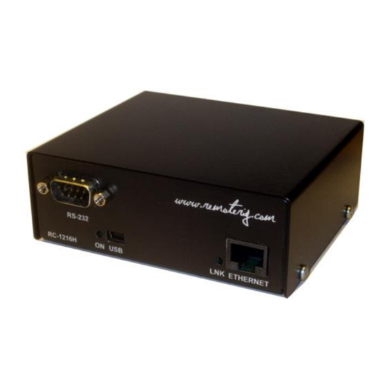
Page 9: Hardware
TXD (out) (*Only used for Expert available after 2014-june-01) (* the DTR signal can be added easily by the user in older version) Microbit 2.0 AB 2010. All rights reserved Ba-RC1216H-PA9 Rev. PA9 – 2014 Sept 10 User manual... - Page 10 In [+] In [-] Green LED indicates link OK flashing LED indicates traffic Yellow LED indicates speed = 100Mbit/s (off = 10MBits/s) Microbit 2.0 AB 2010. All rights reserved Ba-RC1216H-PA9 Rev. PA9 – 2014 Sept 10 User manual 10 of 79...
-
Page 11: Back
USER MANUAL RC-1216H Back The RC-1216H is powered via the PWR connector (2.1/5.5 mm) with 10-18 VDC. A DC-cord is included with the product. 12V DC Pin no + 10-18 VDC (centre) PWR SW Inside the box is a Relay (230V/16A) connected to the socket block. Safety regulations says that max 50V can be switched with this Relay output. -
Page 12: Configuration With Microbit Setup Manager
The initial settings of the network parameters are easiest done with the Microbit Setup Manager. The Setup Manager is a software which runs under Windows on a PC and connects to the RC via USB (an USB cable is supplied with the RC-1216H).The Setup Manager can be used for: ... -
Page 13: Fw/Hw
If there is a newer firmware available download it to your desktop, unzip it. Change to the "FW-update" tab. Microbit 2.0 AB 2010. All rights reserved Ba-RC1216H-PA9 Rev. PA9 – 2014 Sept 10... -
Page 14: Fw Update
After about a 1 minute the update is finished and the RC will restart. When the text "RC- connected" shows up again in the lower field of the Microbit Setup Manager, you can change to the "FW/HW" tab and check software version. -
Page 15: Setup
"1216H-connected" shows up again in the lower field of the Setup- Manager, you can click on the "Setup" button again to verify the changes. Microbit 2.0 AB 2010. All rights reserved Ba-RC1216H-PA9 Rev. PA9 – 2014 Sept 10... -
Page 16: Net Info
USER MANUAL RC-1216H Net info Click on the “Get” button to read the IP setting currently in use by the RC-1216H. Microbit 2.0 AB 2010. All rights reserved Ba-RC1216H-PA9 Rev. PA9 – 2014 Sept 10 User manual... -
Page 17: Initial Ip Setup
The default Ip settings from the factory is 192.168.0.236. The net mask is 255.255.255.0, gateway and DNS is 192.168.0.1. To be able to contact the RC-1216H via the network you must configure the units to fit into your home network. You can check your network configuration from your PC. - Page 18 USER MANUAL RC-1216H The Netmask is 255.255.255.0 the Netmask in the RC-1216H should be the same The Default gateway 192.168.0.1 the Gateway and DNS server(*) in the RC should be the same In this case all the default IP setting will be OK.
- Page 19 RC-1216H In another network, this is the result of the ipconfig command. Your PC IP address in this example is 192.168.128.10 this means that the IP of the RC-1216H must have IP:s in the area 192.168.128.2 to 192.168.128.255. The Netmask is 255.255.128.0 this the Netmask in the RC should be the same The Default gateway is 192.168.128.1 the Gateway in the RC-1216H should be the same...
- Page 20 USER MANUAL RC-1216H Microbit 2.0 AB 2010. All rights reserved Ba-RC1216H-PA9 Rev. PA9 – 2014 Sept 10 User manual 20 of 79...
-
Page 21: Configuration With Web-Interface
RC-1216H Configuration with WEB-interface Before you can use your RC-1216H you must configure it. The unit will have the default IP addresses 192.168.0.236. The net mask is 255.255.255.0. The configuration is easiest done via the web interface. Be aware of that your PC must be in the same net e.g. having an IP- number between 192.168.0.2 and 192.168.0.254 and not be the same as the RC-1216H. - Page 22 USER MANUAL RC-1216H The info page shows some static information about the RC-1216H as firmware revision etc. and also the basic IP-configuration. Microbit 2.0 AB 2010. All rights reserved Ba-RC1216H-PA9 Rev. PA9 – 2014 Sept 10...
-
Page 23: Ip Settings
The IP Settings menu is used to setup the initial IP parameters needed for the unit to connect to the IP network. Down below the settings are described more in details. Microbit 2.0 AB 2010. All rights reserved Ba-RC1216H-PA9 Rev. - Page 24 100 Mbit LAN (*) If you use fixed settings you must have a managed switch where you can set the same setting. Microbit 2.0 AB 2010. All rights reserved Ba-RC1216H-PA9 Rev. PA9 – 2014 Sept 10 User manual...
- Page 25 “empty” (default) “username” Web page pwd Password for the web pages and telnet connection. “empty” (default) “password” Microbit 2.0 AB 2010. All rights reserved Ba-RC1216H-PA9 Rev. PA9 – 2014 Sept 10 User manual 25 of 79...
-
Page 26: Dynamic Dns Setting
RC-1216H Dynamic DNS setting The RC-1216H has a Dynamic DNS client to be used when the Internet Service Provider (ISP) uses dynamic IP addresses instead of fixed IP address. The RC-1216H supports our own free Remoterig dynamic DNS service and DynDNS which is not free anymore. You can choose to use one of them. -
Page 27: Remoterig Dynamic Dns Service
USER MANUAL RC-1216H Remoterig dynamic dns service The Remoterig dynamic dns service only support equipment from Remoterig and Microbit like the RC-1216H, RRC-1258 and the WebSwitch 1216H etc. The Remoterig dynamic dns service do not need any registration it’s automatically generated based on the serial number on the equipment. - Page 28 USER MANUAL RC-1216H After the RC-1216H has restarted go back to the Dynamic DNS settings page. You will now see that the settings Own hostname, Username and Password are automatically generated. The only important information is the Own host name, copy the whole row, this is the information you should put into your web browsers address field when you contact the unit in the future.
-
Page 29: Dyndns Dynamic Dnsservice
IP address in we browsers address field and you don't need to bother if the IP address at the remote QTH changes. You need to register an account at http://www.dyndns.com/services/dns/dyndns/ and get a domain name. There are other providers of the same service but RC-1216H only supports DynDNS or Remoterig ddns. Parameter Setting ... - Page 30 Own host name Domain name registered at DynDNS.com. Example: my-radio-site.ham-radio-op.net Username Dynamic DNS account username. Password Dynamic DNS account password. Microbit 2.0 AB 2010. All rights reserved Ba-RC1216H-PA9 Rev. PA9 – 2014 Sept 10 User manual 30 of 79...
-
Page 31: Application Firmware Upgrade
Note -- Do not interrupt the upgrade process in any way. Wait a minute or two then connect to the RC-1216H again and select 'Info' and verify that the Software version is updated. If it looks like its not updated empty the web browser cache, to prevent it from showing an old cached page. -
Page 32: Bootloader Firmware Upgrade
This follows the same steps as the application firmware upgrade procedure above. Restart device Restart device can be used if you want to reset and restart the RC-1216H without saving any changes (before apply changes) or just for ordinary reset. -
Page 33: Portforwarding
There is one row assigned for each port (service) all refereeing to the IP of the Radio-RRC and the RC-1216H at the 5 row. Microbit 2.0 AB 2010. All rights reserved Ba-RC1216H-PA9 Rev. PA9 – 2014 Sept 10 User manual... -
Page 34: Rc-1216H Setup For Steppir Antenna Control
SDA-100 Control box. If you want to be able to switch between automatic adjustment and manual you have to connect the data line from the radio to the SDA-100 via the RC-1216H AUX-SW1 Relay as there the SDA-100 protocol do not support switching on/off the Autotrack remotely (We hope they will implement it later). -
Page 35: Installation Of The Rc-1216H For Steppir Control
RC-1216H Manual. You have also to prepare the cabling and do the Initial setup, see Step by step RC- 1216H setup. Installation of the RC-1216H for SteppIR control Microbit 2.0 AB 2010. All rights reserved Ba-RC1216H-PA9 Rev. PA9 – 2014 Sept 10... -
Page 36: Settings For Steppir
Click on the Advanced settings link to the left, When the advanced settings page shows up, select SteppIR from the “Function type” drop down. Click on submit to store the settings. Microbit 2.0 AB 2010. All rights reserved Ba-RC1216H-PA9 Rev. PA9 – 2014 Sept 10... - Page 37 Depending on if how you have connected the CAT cable to the SDA 100 it can also go to the Radio frequency. If you have connected the CAT cable via the RC-1216H AUX-SW1 you have to click on the “serial” button to get automatic updates from the radio.
- Page 38 DC power the first time. If you are on site never switch off the SDA-100 with the PWR switch to disturb the status memory. Microbit 2.0 AB 2010. All rights reserved Ba-RC1216H-PA9 Rev.
-
Page 39: Rc-1216H Setup For Acom 2000A Control
RCU like Forward power, Reflected power, Alarm LED:s, Band segment, Temp indicators etc. A serial cable has to be connected from the RC-1216H to the PA RS-232 port. If you also have the ACOM antenna switch you need to make a special Y-cable. Another cable is needed from the RC-1216H AUX-SW1 socket to the PA for Remote power on. -
Page 40: Installation With Acom-2000A
USER MANUAL RC-1216H Before you can start using the RC-1216H. You have also to prepare the cabling and do the Initial setup, see Step by step RC-1216H setup. Installation with ACOM-2000A Standard installation of the RC-1216H and ACOM-2000A... -
Page 41: Acom-2000A With Acom-2000S Antenna Switch
When the ACOM-2000S antenna switch is already connected to the RS-232 port at the PA you must use a split cable. RC-1216H ACOM-2000A D-SUB D-SUB SERIAL CABLE 9P-F 9P-F ACOM-2000S Antenna Switch D-SUB 9P-F Microbit 2.0 AB 2010. All rights reserved Ba-RC1216H-PA9 Rev. PA9 – 2014 Sept 10 User manual 41 of 79... -
Page 42: Acom-2000A - 230Vac Power Switching
RC-1216H ACOM-2000A – 230VAC Power switching If you need to control the 230VAC Mains power a relay can be controlled by the RC-1216H. Be sure it’s 2-pole relay and that it can handle the large current needed by the ACOM-2000A (16A at 230V). -
Page 43: Settings For Acom-2000A
Click on the Advanced settings link to the left, When the advanced settings page shows up, select ACOM 2000A from the “Function type” drop down. Click on submit to store the settings. Microbit 2.0 AB 2010. All rights reserved Ba-RC1216H-PA9 Rev. PA9 – 2014 Sept 10... - Page 44 In normal cases the default values will work if you have not change the settings in the PA. Cclick on “apply changes” to update the RC-1216H with the new settings. The Unit will restart. After restart you will see the ACOM 2000 window.
- Page 45 < > buttons on the RCU. Read parameters can be used to read all measured values etc. from the PA, a pop up window will show them. Microbit 2.0 AB 2010. All rights reserved Ba-RC1216H-PA9 Rev. PA9 – 2014 Sept 10...
- Page 46 USER MANUAL RC-1216H Microbit 2.0 AB 2010. All rights reserved Ba-RC1216H-PA9 Rev. PA9 – 2014 Sept 10 User manual 46 of 79...
- Page 47 If you do not have a relay connected you need to use the “Main Power” button anyway, otherwise the PWR-ON button will not be visible. Microbit 2.0 AB 2010. All rights reserved Ba-RC1216H-PA9 Rev. PA9 – 2014 Sept 10...
-
Page 48: Rc-1216H Setup For Expert 1K-Fa Control
PA from any device with a web browser like smartphones, pads etc. A serial cable has to be connected from the RC-1216H to the PA RS-232 port. It’s should be a standard RS-232 cable with straight connection 9PF -9PM. If you have a RC-1216H produced before 2014-june-01 you have to make a small modification to get the DTR signal working, see mods under the support tab on the Remoterig website. -
Page 49: Installation With Expert 1K-Fa
PWR SW relay. The AUX SW1 relay can be setup to follow either the Main PWR button or the PWR ON/OFF button (see below). Before you can start using the RC-1216H. You have also to prepare the cabling and do the Initial setup, see Step by step RC-1216H setup. -
Page 50: Edxpert 1K-Fa - 230Vac Power Switching
Edxpert 1K-FA – 230VAC Power switching If you need to control the 230VAC Mains power a relay can be controlled by the RC-1216H. Be sure it’s 2-pole relay and that it can handle the large current needed by the Expert 1K-FA (10A at 230V). -
Page 51: Settings For Expert 1K-Fa
Click on the Advanced settings link to the left, When the advanced settings page shows up, select Expert 1K-FA from the “Function type” drop down. Click on submit to store the settings. Microbit 2.0 AB 2010. All rights reserved Ba-RC1216H-PA9 Rev. PA9 – 2014 Sept 10... - Page 52 In normal cases the default values will work if you have not change the settings in the PA. Click on “apply changes” to update the RC-1216H with the new settings. The Unit will restart. After restart you will see the Expert window.
- Page 53 OUTPUT POWER - Switching between half and full DISPLAY CMD - Used to clear the alarms, like overdriving etc. MAIN PWR - Controls the Relay for Mains on the RC-1216H. (must be on even if you have not connected the relay)
-
Page 54: Error And Warnings
In operate mode the PWR scale is rescaled and are showing PA output power. ATTENTION ! Before you try to operate the PA via RC-1216H be sure that you have done all settings in the PA, connected all cables and that you are able to use the PA as normal controlled from the front panel of the PA. - Page 55 USER MANUAL RC-1216H Microbit 2.0 AB 2010. All rights reserved Ba-RC1216H-PA9 Rev. PA9 – 2014 Sept 10 User manual 55 of 79...
-
Page 56: Aux Sw1 Relay
AUX SW1 should behave. It can be set to follow either the Main on/off button or the on/off button. I use it myself to control a koax relay which switch between the Solid state and Tube PA. Microbit 2.0 AB 2010. All rights reserved Ba-RC1216H-PA9 Rev. PA9 – 2014 Sept 10... -
Page 57: Serial Port Server
RC-1216H Serial port server The RC-1216H can act as a serial port server in parallel with the web interface, meaning that you can use the Expert PC software to control the PA simultaneously. This is convenient if you need to change some settings like the automatic selection of antenna ports or other things which the web interface do not support. -
Page 58: Using Setup Microbit Setup Manager To Create A Virtual Serial Port
Using Setup Microbit Setup Manager to create a virtual serial port Start the Microbit Setup Manager (it must be v1.27 or later), select the serial port tab, select a free serial port, enter the IP address or DDNS hostname and the same TCP port as you set in the RC-1216H. - Page 59 When you have selected serial port go back to the Setup Manager Window and click on the refresh button. Now Port status should change to “Connected”. Microbit 2.0 AB 2010. All rights reserved Ba-RC1216H-PA9 Rev. PA9 – 2014 Sept 10...
- Page 60 USER MANUAL RC-1216H Browse the System info page in the RC-1216H you should see that RFC2217 now have changed to “connected”. If you already have the page up, click F5 to refresch the page. Be sure that the PA is ON, if not switch it ON from the web page.
- Page 61 Setup Manager any more to use the port. You only need the Setup manager if you want to make some changes or check the status Microbit 2.0 AB 2010. All rights reserved Ba-RC1216H-PA9 Rev. PA9 – 2014 Sept 10...
-
Page 62: Rc-1216H Setup For Elecraft Kpa500 Control
PA from any device with a web browser like smartphones, pads etc. A serial cable has to be connected from the RC-1216H to the PA RS-232 port. It’s should be a standard RS-232 cable with straight connection 9PF -9PM. -
Page 63: Installation With Elecraft Kpa500
The AUX SW1 relay can be setup to follow either the Main PWR button or the PWR ON/OFF button ( see below). Before you can start using the RC-1216H. You have also to prepare the cabling and do the Initial setup, see Step by step RC-1216H setup. -
Page 64: Elecraft Kpa-500 - 230Vac Power Switching
RC-1216H Elecraft KPA-500 – 230VAC Power switching If you need to control the 230VAC Mains power a relay can be controlled by the RC-1216H. Be sure it’s 2-pole relay and that it can handle the current needed by the KPA-500. - Page 65 USER MANUAL RC-1216H Microbit 2.0 AB 2010. All rights reserved Ba-RC1216H-PA9 Rev. PA9 – 2014 Sept 10 User manual 65 of 79...
- Page 66 In normal cases the default values will work if you have not change the settings in the PA. Click on “apply changes” to update the RC-1216H with the new settings. The Unit will restart. After restart you will see the KPA500 window.
- Page 67 The selected band, operating status and temp are shown as they are reported from the PA. There are control buttons for MAIN PWR - Controls the Relay for Mains on the RC-1216H. (must be on even if you have not connected the relay)
- Page 68 In operate mode the PWR scale is rescaled and are showing PA output power. ATTENTION ! Before you try to operate the PA via RC-1216H be sure that you have done all settings in the PA, connected all cables and that you are able to use the PA as normal controlled from the front panel of the PA.
-
Page 69: Error And Warnings
AUX SW1 should behave. It can be set to follow either the Main on/off button or the on/off button. I use it myself to control a koax relay which switch between the Solid state and Tube PA. Microbit 2.0 AB 2010. All rights reserved Ba-RC1216H-PA9 Rev. PA9 – 2014 Sept 10... -
Page 70: Rc-1216H Setup For Rotator Control
There are also 8 memory buttons which you can program to your favorite directions. A serial cable has to be connected from the RC-1216H to the rotator control box or serial interface. The example shows cabling for the Prosistel rotators. If you have others check the rotator manual for the connector pinning so you make proper cables. -
Page 71: Installation Example With Prosistel Or Alfaspid
USER MANUAL RC-1216H Before you can start using the RC-1216H. You have also to prepare the cabling and do the Initial setup, see Step by step RC-1216H setup. Installation example with Prosistel or AlfaSpid Standard installation of the RC-1216H and a Prosistel or AlfaSpid rotator. -
Page 72: Rotator - 230Vac Power Switching
RC-1216H Rotator – 230VAC Power switching If you need to control the 230VAC Mains power a relay can be controlled by the RC-1216H It should be connected to the PWR-SW connector. Be sure it’s 2-pole relay and that it can handle the current and voltage needed. -
Page 73: Settings For Rotator Control
“Function type” drop down. We use Prosistel in the example. Click on submit to store the settings. Microbit 2.0 AB 2010. All rights reserved Ba-RC1216H-PA9 Rev. PA9 – 2014 Sept 10... - Page 74 On the lines below you can set a azimuth and a corresponding text for the 8 preset buttons. When done click on “submit” and “apply changes”. The unit will restart. Microbit 2.0 AB 2010. All rights reserved Ba-RC1216H-PA9 Rev. PA9 – 2014 Sept 10...
- Page 75 RC-1216H After restart you will see the Rotator Screen Until you have connected the rotator and power it on it will show “Disabled” Microbit 2.0 AB 2010. All rights reserved Ba-RC1216H-PA9 Rev. PA9 – 2014 Sept 10 User manual...
- Page 76 The azimuth readings and the compass will change live while the rotator is moving. The compass will show a rough direction with 5 degrees resolution. Microbit 2.0 AB 2010. All rights reserved Ba-RC1216H-PA9 Rev. PA9 – 2014 Sept 10...
-
Page 77: Appendix D - Technical Data
USB 2.0 (mini) Serial port : RS-232 (1200-57600 baud) Usable temp range: 0 to +40 °C Humidity range: 30% to 90% RH Microbit 2.0 AB 2010. All rights reserved Ba-RC1216H-PA9 Rev. PA9 – 2014 Sept 10 User manual 77 of 79... -
Page 78: Appendix E - Safety And Regulatory Information
Never connect a power supply of more than 18 VDC to the power jack. The supply voltage must be between 10 V and 18 V. to prevent damaging the device. Microbit 2.0 AB 2010. All rights reserved Ba-RC1216H-PA9 Rev. PA9 – 2014 Sept 10... -
Page 79: Disclaimer
The author has written this document to the best of his knowledge, but does not guarantee that the contents will satisfy the desire and expectation of the reader. The author or Microbit takes no responsibility for damage or injuries of any kind that may arise from the use and miss use of the product or information contained.
Need help?
Do you have a question about the RC-1216H and is the answer not in the manual?
Questions and answers