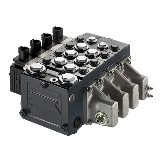
Danfoss PVG 16 Technical Information
Proportional valve group
Hide thumbs
Also See for PVG 16:
- Service manual (28 pages) ,
- Service and parts manual (144 pages) ,
- Installation manual (6 pages)
Table of Contents
Advertisement
Quick Links
Advertisement
Table of Contents

Subscribe to Our Youtube Channel
Related Manuals for Danfoss PVG 16


Summary of Contents for Danfoss PVG 16
- Page 1 Technical Information PVG 16 Proportional Valve Group www.danfoss.com...
- Page 2 Technical Information PVG 16 Proportional Valve Group Revision history Table of revisions Date Changed December 2018 Major rework of document: new sections added, data corrected. 0901 October 2018 'PVBS Main Spools' section reworked. 'Safety in Systems' and 'PVB Basic Modules 0801 Accessories' sections added.
-
Page 3: Table Of Contents
Technical Information PVG 16 Proportional Valve Group Contents General Information General Description..................................5 PVG 16 Features....................................5 Safety in Systems....................................6 PVG 16 Modules Overview................................8 PVP Inlet Modules Open Center PVP....................................10 Open Center PVP with PPRV..............................13 Open center PVP with HPCO and PVE PPRV.........................17 Closed Center PVP.................................. - Page 4 PVG 32/16 Dimensions.................................98 PVG 100/16 Dimensions................................100 PVG 120/16 Dimensions................................102 PVG 128/16 Dimensions................................104 PVG 256/16 Dimensions................................106 PVG 16 Applications Schematics PVG 16 Schematic with Basic End Plate..........................108 PVG 16 with P- and T-connection end plate........................109 © Danfoss | December 2018 BC00000211en-000901...
-
Page 5: General Information
The PVG 16 is a member of the PVG product platform and interfaces to other valve families enabling all machine functions being controlled from one single valve stack. PVG 16 controls work port flow up to 65 l/min [17 US gal/min] l/min and up to 420 bar [6090 psi] bar work port pressure. -
Page 6: Safety In Systems
This example breaks down the control system into smaller bits explaining the architecture in depth. Even though many Danfoss components are used in the PVG control system. The function of the control system is to use the output from the PVE together other external sensors to ensure the PLUS+1 main controllers correct function of the aerial lift. - Page 7 A mix of electrical actuation and hydraulic actuation on the same valve stack is not safe. PVE and PVH are designed for different pilot pressure. Cost-free repairs, as mentioned in Danfoss General Conditions of Sale, are carried out only at Danfoss or at service shops authorized by Danfoss.
-
Page 8: Pvg 16 Modules Overview
Technical Information PVG 16 Proportional Valve Group General Information PVG 16 Modules Overview PVG proportional valve group shown in the exploded view illustration for a quick modules navigation. PVG 16 Modules Assembly Overview PVBS PVH/Covers PVHC PVAS PVG Modules Navigation:... -
Page 9: Pvp Inlet Modules
PVG 16 Proportional Valve Group PVP Inlet Modules The PVG 16 PVP inlet modules, also referred to as pump side modules, act as an interface between the PVG 16 proportional valve group and the hydraulic pump and tank reservoir. PVP Inlet Module PVP inlet module dimensions 23 [0.9]... -
Page 10: Open Center Pvp
Technical Information PVG 16 Proportional Valve Group PVP Inlet Modules Open Center PVP The basic Open Center PVP inlet module is intended for use with fixed displacement pumps in applications, where a valve group with mechanically controlled work sections is desired, or where the pilot pressure to the valve group is supplied externally. - Page 11 Technical Information PVG 16 Proportional Valve Group PVP Inlet Modules Theoretical Performance Graphs Integrated LS pressure relief valve characteristics [psi] (bar) 4000 3000 2000 1000 [l/min] [US gal/min] Neutral by-pass pressure drop characteristics [psi] (bar) (l/min) [US gal/min] Part numbers for Open Center PVP...
- Page 12 Technical Information PVG 16 Proportional Valve Group PVP Inlet Modules Part numbers for Open Center PVP (continued) Part number P-port T-port LS-, M-port (LS1 T0-port Mounting PVPX JIS 1/2 JIS 3/4 JIS 1/4 157B5925 G1/2 G3/4 G1/4 157B5945 1 1/16-12 UNF...
-
Page 13: Open Center Pvp With Pprv
Technical Information PVG 16 Proportional Valve Group PVP Inlet Modules Open Center PVP with PPRV The Open Center PVP inlet with integrated pilot pressure reduction valve (PPRV) is intended for use with fixed displacement pumps in applications, where a valve group with electro-hydraulically or hydraulically controlled work sections is desired (PVE or PVH/PVHC). - Page 14 Technical Information PVG 16 Proportional Valve Group PVP Inlet Modules Theoretical Performance Graphs Integrated LS pressure relief valve characteristics [psi] (bar) 4000 3000 2000 1000 [l/min] [US gal/min] Neutral by-pass pressure drop characteristics [psi] (bar) (l/min) [US gal/min] Pilot pressure reduction valve characteristics...
- Page 15 Technical Information PVG 16 Proportional Valve Group PVP Inlet Modules Part numbers for Open Center PVP with PPRV Part number Actuation P-port T-port LS-port M-port Pp-port T0-port Mounting PVPX G1/2” G3/4” G1/4” G1/4” 157B5010 G1/2” G3/4” G1/4” G1/4” 157B5012 G3/4”...
- Page 16 Technical Information PVG 16 Proportional Valve Group PVP Inlet Modules Part numbers for Open Center PVP with PPRV (continued) Part number Actuation P-port T-port LS-port M-port Pp-port T0-port Mounting PVPX G3/4 G3/4 G1/4 G1/4 157B5977 M22 x 1.5 M22 x 1.5 M12 x 1.5...
-
Page 17: Open Center Pvp With Hpco And Pve Pprv
The integrated HPCO functionality guides the excess flow of the PVG 16 valve group to the external hydraulic subsystem(s), giving priority to the PVG 16 work functions. - Page 18 Technical Information PVG 16 Proportional Valve Group PVP Inlet Modules Theoretical Performance Graphs Integrated LS pressure relief valve characteristics [psi] (bar) 4000 3000 2000 1000 [l/min] [US gal/min] Neutral by-pass pressure drop characteristics [psi] (bar) (l/min) [US gal/min] Pilot pressure reduction valve characteristics...
- Page 19 Technical Information PVG 16 Proportional Valve Group PVP Inlet Modules Part numbers for OC PVP (HPCO and PPRV) Part number P-port HPCO- LS-port M-port Pp-port T0-port Mounting PVPX port G3/4” G3/4" G1/4” G1/4” G1/4” G1/4” 157B5140 G3/4” G3/4" G1/4” G1/4”...
-
Page 20: Closed Center Pvp
Technical Information PVG 16 Proportional Valve Group PVP Inlet Modules Closed Center PVP The basic Closed Center PVP inlet is intended for use with variable displacement pumps in applications where a valve group with mechanically controlled work sections is desired, or where the pilot pressure to the valve group is supplied externally. - Page 21 Technical Information PVG 16 Proportional Valve Group PVP Inlet Modules Theoretical Performance Graphs Integrated LS pressure relief valve characteristics [psi] (bar) 4000 3000 2000 1000 [l/min] [US gal/min] Part numbers for Closed Center PVP Part P-port T-port LS-port M-port T0-port...
-
Page 22: Closed Center Pvp With Pprv
Technical Information PVG 16 Proportional Valve Group PVP Inlet Modules Closed Center PVP with PPRV The Closed Center PVP inlet with integrated pilot pressure reduction valve (PPRV) is intended for use with variable displacement pumps in applications where a valve group with electro-hydraulic or hydraulically controlled work sections is desired. - Page 23 Technical Information PVG 16 Proportional Valve Group PVP Inlet Modules Theoretical Performance Graphs Integrated LS pressure relief valve characteristics [psi] (bar) 4000 3000 2000 1000 [l/min] [US gal/min] Pilot pressure reduction valve characteristics [psi] (bar) (l/min) [US gal/min] Part numbers for Closed Center PVP with PPRV...
- Page 24 Technical Information PVG 16 Proportional Valve Group PVP Inlet Modules Part numbers for Closed Center PVP with PPRV (continued) Part number Actuation P-port T-port LS-port M-port Pp-port T0-port Mounting PVPX (LS1 1 1/16-12 UNF 1 1/16-12 UNF 9/16-18 UNF 9/16-18 UNF...
-
Page 25: Closed Center Pvpv With Pprv
Technical Information PVG 16 Proportional Valve Group PVP Inlet Modules Closed center PVPV with PPRV The Closed Center PVPV inlet with integrated pilot pressure reduction valve (PPRV) is intended for use with variable displacement pumps in applications where a valve group with electro-hydraulic or hydraulically controlled work sections is desired. - Page 26 Technical Information PVG 16 Proportional Valve Group PVP Inlet Modules Part numbers for Closed Center PVPV with PPRV Part number Actuation P-, T-port LS-, M-port Mounting TO-port PVPX G1” G1/4” – 11008856 PVH/PVHC 1 5/16-12 UN 9/16-18 UNF 5/16-18 UNC –...
-
Page 27: Closed Center Pvpvm With Pprv
Technical Information PVG 16 Proportional Valve Group PVP Inlet Modules Closed center PVPVM with PPRV The Closed Center PVPVM mid-inlet module with integrated pilot pressure reduction valve (PPRV) is intended for use with variable displacement pumps in applications where a valve group with electro- hydraulic or hydraulically controlled work sections is desired. - Page 28 Technical Information PVG 16 Proportional Valve Group PVP Inlet Modules Part numbers for Closed Center PVPVM with PPRV Part number Actuation P-, T-port LS-, M-port Mounting PVLP PVH/PVHC 11083156 157B5912 1 5/16-12 UN 9/16-18 UNF 5/16-18 UNC 157B5914 157B5937 G1”...
-
Page 29: Open/Closed Center Pvp With Pprv
Technical Information PVG 16 Proportional Valve Group PVP Inlet Modules Open/Closed center PVP with PPRV The Open Center/Closed Center PVP with integrated pilot pressure reduction valve (PPRV) is intended for use with fixed or variable displacement pumps in applications where the application manufacturer does not determine the pump type. - Page 30 Technical Information PVG 16 Proportional Valve Group PVP Inlet Modules Theoretical Performance Graphs Integrated LS pressure relief valve characteristics [psi] (bar) 4000 3000 2000 1000 [l/min] [US gal/min] Neutral by-pass pressure drop characteristics [psi] (bar) (l/min) [US gal/min] Pilot pressure reduction valve characteristics...
- Page 31 Technical Information PVG 16 Proportional Valve Group PVP Inlet Modules Part numbers for Open/Closed Center PVP with PPRV Part number Actuation P-port T-port LS-port (LS1 ) M-port T0-port Mounting LS Boost 11093273 G3/4 G3/4 G1/4 11119094 G3/4 G3/4 G1/4 11119095...
-
Page 32: Open/Closed Center Pvpm
Technical Information PVG 16 Proportional Valve Group PVP Inlet Modules Open/Closed center PVPM The Open Center/Closed Center PVPM mid-inlet acts as a simple manifold and is intended for use with fixed or variable displacement pumps. The PVPM features no logic other than a PVLP shock/anti- cavitation valve facility for pressure peak protection and anti-cavitation prevention. -
Page 33: Pvp Inlet Module Accessories
Technical Information PVG 16 Proportional Valve Group PVP Inlet Module Accessories The generic PVP inlet module accessory platform includes the PVPX Electrical LS pressure unloading valve, External pilot pressure adapters PVPC with or without check valve for all Open Center PVP with PPRV. -
Page 34: Part Numbers For Pvpx
Technical Information PVG 16 Proportional Valve Group PVP Inlet Module Accessories PVPX technical data (continued) 155°C [311°F] Max. coil surface temperature 3/4-16 UNF Thread size Technical specification Parameter Minimum Recommended range Maximum -30°C [-22°F] 30 to 60°C [86 to 140°F] 90°... - Page 35 Technical Information PVG 16 Proportional Valve Group PVP Inlet Module Accessories Part numbers for PVPX, NOMO configuration (continued) Part number Manual Override Voltage Supply Connector IP Rating PUSH 12 V 11193839 PUSH 24 V 11193836 1x2 DEUTSCH IP 67 PUSH...
-
Page 36: Pvpc Without Check Valve
Technical Information PVG 16 Proportional Valve Group PVP Inlet Module Accessories PVPC without Check Valve The PVPC external pilot pressure adapter without check valve is an accessory in the M-port available for PVP inlet modules with integrated pilot pressure reduction valve (PPRV). -
Page 37: Pvpc With Check Valve
Technical Information PVG 16 Proportional Valve Group PVP Inlet Module Accessories PVPC with Check Valve The PVPC external pilot pressure adapter with check valve is an accessory in the M-port available for PVP inlet modules with integrated pilot pressure reduction valve (PPRV). -
Page 38: Pvb Basic Modules
PVG 16 Proportional Valve Group PVB Basic Modules The PVG 16 PVB basic modules, also referred to as work sections, are the interface between the PVG 16 proportional valve group and the work function such as a cylinder or a motor. -
Page 39: Compensated Pvb
Technical Information PVG 16 Proportional Valve Group PVB Basic Modules Compensated PVB The compensated PVB is intended for controlling a work function where the function behavior in terms of flow and pressures requires independence on the load pressure of other functions used simultaneously. - Page 40 Technical Information PVG 16 Proportional Valve Group PVB Basic Modules Performance graphs (Theoretical) Fluid flow as a function of spool travel Spool types: AA = 5/min A = 10 l/min B = 15 l/min C = 25 l/min D = 40 l/min...
- Page 41 Technical Information PVG 16 Proportional Valve Group PVB Basic Modules Load Independent Fluid Flow – Pressure Compensated PVB (l/min) [US gal/min] AA = 5/min A = 10 l/min B = 15 l/min C = 25 l/min D = 40 l/min...
-
Page 42: Compensated Pvb With Pvlp/Pvla
Technical Information PVG 16 Proportional Valve Group PVB Basic Modules Compensated PVB with PVLP/PVLA The compensated PVB featuring an optional PVLP/PVLA shock and anti-cavitation valves on each work port for pressure peak protection and anti-cavitation prevention. The compensated PVB is intended for controlling a work function where the function behavior in terms of flow and pressures requires independence on the load pressure of other functions used simultaneously. - Page 43 Technical Information PVG 16 Proportional Valve Group PVB Basic Modules Performance graphs (Theoretical) Fluid flow as a function of spool travel Spool types: AA = 5/min A = 10 l/min B = 15 l/min C = 25 l/min D = 40 l/min...
- Page 44 Technical Information PVG 16 Proportional Valve Group PVB Basic Modules PVLP shock valve characteristics [psi] (bar) 6000 5000 4000 3000 2000 1000 (l/min) [US gal/min] PVLP/PVLA suction valve characteristics [psi] [bar] PVLP PVLA 10 15 20 25 30 35 40 45...
- Page 45 Technical Information PVG 16 Proportional Valve Group PVB Basic Modules Load Independent Fluid Flow – Pressure Compensated PVB (l/min) [US gal/min] AA = 5/min A = 10 l/min B = 15 l/min C = 25 l/min D = 40 l/min...
-
Page 46: Compensated Pvb With Ls A/B
Technical Information PVG 16 Proportional Valve Group PVB Basic Modules Compensated PVB with LS A/B The compensated PVB is intended for controlling a work function where the function behavior in terms of flow and pressures requires independency on the load pressure of other functions used simultaneously. - Page 47 Technical Information PVG 16 Proportional Valve Group PVB Basic Modules Performance graphs (Theoretical) Fluid flow as a function of spool travel Spool types: AA = 5/min A = 10 l/min B = 15 l/min C = 25 l/min D = 40 l/min...
- Page 48 Technical Information PVG 16 Proportional Valve Group PVB Basic Modules PVB pressure compensated for LS A/B characteristics (l/min) [US gal/min] (bar) [psi] 1000 1500 2000 2500 3000 3500 4000 4500 5000 Load Independent Fluid Flow – Pressure Compensated PVB (l/min)
- Page 49 Technical Information PVG 16 Proportional Valve Group PVB Basic Modules PVB pressure compensated P-line and T-line characteristics [psi] (bar) Port A/B T-line P-line (l/min) [US gal/min] Part numbers for Compensated PVB with LS A/B Part number A/B-port 3/8” BSP 11130982 3/4”...
-
Page 50: Uncompensated Pvb
Technical Information PVG 16 Proportional Valve Group PVB Basic Modules Uncompensated PVB The uncompensated PVB is intended for controlling a work function where the function behavior in terms of flow and pressures requires independence on the load pressure of other functions used simultaneously. - Page 51 Technical Information PVG 16 Proportional Valve Group PVB Basic Modules Performance graphs (Theoretical) Fluid flow as a function of spool travel Spool types: AA = 5/min A = 10 l/min B = 15 l/min C = 25 l/min D = 40 l/min...
- Page 52 Technical Information PVG 16 Proportional Valve Group PVB Basic Modules Part numbers for Uncompensated PVB Part number A/B-port Check valve 3/8” BSP 11106801 3/8” BSP — 11101421 3/4” – 16 UNF 11106797 3/4” – 16 UNF — 11101423 52 | ©...
-
Page 53: Uncompensated Pvb With Pvlp
Technical Information PVG 16 Proportional Valve Group PVB Basic Modules Uncompensated PVB with PVLP The uncompensated PVB featuring an optional PVLP shock valve on each work port for pressure peak protection and anti-cavitation prevention, is intended for controlling a work function where the function behavior in terms of flow and pressures requires independence on the load pressure of other functions used simultaneously. - Page 54 Technical Information PVG 16 Proportional Valve Group PVB Basic Modules Performance graphs (Theoretical) Fluid flow as a function of spool travel Spool types: AA = 5/min A = 10 l/min B = 15 l/min C = 25 l/min D = 40 l/min...
- Page 55 Technical Information PVG 16 Proportional Valve Group PVB Basic Modules PVLP shock valve characteristics [psi] (bar) 6000 5000 4000 3000 2000 1000 (l/min) [US gal/min] PVB pressure compensated P-line and T-line characteristics [psi] (bar) Port A/B T-line P-line (l/min) [US gal/min]...
-
Page 56: Pvlp Shock And Anti-Cavitation Valve
Technical Information PVG 16 Proportional Valve Group PVB Basic Modules PVLP Shock and Anti-Cavitation Valve The PVLP shock and anti-cavitation valve will relieve a pressure peak to the internal tank galleries and will furthermore suck oil from the tank to the work port to prevent cavitation. Pressure settings range: 32–400 bar [460–5801 psi]. - Page 57 Technical Information PVG 16 Proportional Valve Group PVB Basic Modules PVLP/PVLA suction valve characteristics [psi] [bar] PVLP PVLA 10 15 20 25 30 35 40 45 50 55 60 65 70 75 80 85 90 95 100 105 110 115 120...
-
Page 58: Pvb Basic Modules Accessories
Technical Information PVG 16 Proportional Valve Group PVB Basic Modules Accessories The generic PVB module accessory platform include the PVLP shock and anti-cavitation valve and PVLA suction valve. • PVLP Shock and Anti-Cavitation Valve on page 56 • PVLA Suction Valve... -
Page 59: Pvlp Shock And Anti-Cavitation Valve
Technical Information PVG 16 Proportional Valve Group PVB Basic Modules Accessories PVLP Shock and Anti-Cavitation Valve The PVLP shock and anti-cavitation valve will relieve a pressure peak to the internal tank galleries and will furthermore suck oil from the tank to the work port to prevent cavitation. Pressure settings range: 32–400 bar [460–5801 psi]. - Page 60 Technical Information PVG 16 Proportional Valve Group PVB Basic Modules Accessories PVLP/PVLA suction valve characteristics [psi] [bar] PVLP PVLA 10 15 20 25 30 35 40 45 50 55 60 65 70 75 80 85 90 95 100 105 110 115 120...
-
Page 61: Pvla Suction Valve
Technical Information PVG 16 Proportional Valve Group PVB Basic Modules Accessories PVLA Suction Valve The PVLA valve is an accessory available for PVB basic modules. The PVLA will suck fluid from the tank to the work port to prevent cavitation by the 0.5 bar spring. The plug will ensure that when using a single acting spool, all flow returning through the work port is led to tank. -
Page 62: Pvbs Main Spools
Technical Information PVG 16 Proportional Valve Group PVBS Main Spools The main spools (PVBS) determine the flow out of the work section or the pressure build up and are based on a generic platform with a wide selection of additional features, enabling you to tailor the PVBS to suit the demands of any hydraulic system and any function. -
Page 63: Pvbs Fluid Flow Characteristics - Theoretical Performance
Technical Information PVG 16 Proportional Valve Group PVBS Main Spools PVBS Fluid Flow Characteristics - Theoretical Performance Fluid flow as a function of spool travel Spool types: AA = 5/min A = 10 l/min B = 25 l/min C = 40 l/min... - Page 64 Technical Information PVG 16 Proportional Valve Group PVBS Main Spools Fluid flow as a function of spool travel (asymmetrical spools) Spool types: AA = 5/min A = 10 l/min B = 15 l/min C = 25 l/min D = 40 l/min E = 65 l/min 0.25...
- Page 65 Technical Information PVG 16 Proportional Valve Group PVBS Main Spools Pressure drop to T (open spool in neutral) [psi] (bar) 4000 3600 3200 2800 2400 Pressure drop for PVBS 65 l/min 2000 1600 1200 [l/min] [US gal/min] © Danfoss | December 2018...
-
Page 66: Pvbs Main Spools Part Numbers
Technical Information PVG 16 Proportional Valve Group PVBS Main Spools Part Numbers Flow Control Spools - Closed Neutral Position Schematic for PVBS - 4-way, 3 positions Schematic for PVBS - 4-way, 4 positions Symmetrical spools Part number Actuation Flow – l/min [US gal/min] A →... -
Page 67: Flow Control Spools - Throttled Open Neutral Position
Technical Information PVG 16 Proportional Valve Group PVBS Main Spools Part Numbers Flow Control Spools - Throttled Open Neutral Position Schematic for PVBS - 4-way, 3 positions Schematic for PVBS - 4-way, 4 positions Part number Actuation Flow – l/min [US gal/min] A →... -
Page 68: Flow Control Spools - Open/Closed Neutral Position
Technical Information PVG 16 Proportional Valve Group PVBS Main Spools Part Numbers Flow Control Spools - Open/Closed Neutral Position Schematic for PVBS - 4-way, 3 positions Schematic for PVBS - 4-way, 4 positions Asymmetrical spools Part number Actuation* Flow – l/min [US gal/min] A →... -
Page 69: Pvg 16 Actuation
Technical Information PVG 16 Proportional Valve Group PVG 16 Actuation PVG 16 actuation can be done manually, hydraulically, electro-hydraulically and electrically. PVG 16 actuation overview: • PVM Manual Actuation on page 69 PVMD Cover on page 70 ‒ • PVH Hydraulic Actuation on page 71 •... -
Page 70: Pvmd Cover
Technical Information PVG 16 Proportional Valve Group PVG 16 Actuation PVM torque data Spool displacement PVM+PVH PVM+PVMD PVM+PVE From neutral position 2.2 ± 0.2 N•m 2.7 ± 0.2 N•m [19.5 ± 1.8 lb•in] [23.9 ± 1.8 lb•in] Max. spool travel 2.8 ±... -
Page 71: Pvh Hydraulic Actuation
Technical Information PVG 16 Proportional Valve Group PVG 16 Actuation PVH Hydraulic Actuation The PVH hydraulic actuation is intended for use on any work section where the operator wants to have a possibility to interact with the main spool via a hydraulic joystick. The spool spring package must match with this activation method. - Page 72 Technical Information PVG 16 Proportional Valve Group PVG 16 Actuation Technical data 5 – 15 bar [73 – 218 psi] Main spool spring control pressure range 30 bar [435 psi] Maximum pilot oil pressure 10 bar [145 psi] Maximum pressure on port T...
-
Page 73: Pvhc Electro-Hydraulic Actuation
Technical Information PVG 16 Proportional Valve Group PVG 16 Actuation PVHC Electro-Hydraulic Actuation The PVHC is an electrical actuator module for main spool control. The PVHC control is done by dual Pulse Width Modulated, high current supply 100-400 Hz PWM control signals. The spool position will shift when conditions are changed such as temperature change. - Page 74 Technical Information PVG 16 Proportional Valve Group PVG 16 Actuation PVHC spool stroke vs current characteristics PVHC characteristics – Spool stroke vs current Spool stroke, mm Ideal curve Hysteresis [Current in mA] [Current in mA] 1600 @12V 1600 1400 1200...
-
Page 75: Pve Electro-Hydraulic Actuation
All proportional actuators feature a closed- loop spool control and continuous fault monitoring. The analog PVE Series 6 actuator program for PVG 16 features two different main hydraulic principle variants (PVEO and PVEA). - Page 76 Technical Information PVG 16 Proportional Valve Group PVG 16 Actuation PVG 16 with PVEA sectional view PVE Series 6 Overview ON/OFF voltage control, non-proportional functions Proportional spool control for work functions PVEO Series 6 PVEA Series 6 For more information please see PVEO on page 77.
-
Page 77: Pveo
Technical Information PVG 16 Proportional Valve Group PVG 16 Actuation PVEO The PVEO actuator is a non-proportional ON/OFF control actuator with open-loop spool control primarily used to control simple ON/OFF work functions where a proportional control of speed or oil flow is not a requirement. - Page 78 Technical Information PVG 16 Proportional Valve Group PVG 16 Actuation PVEO Series 6 schematic PVEO Series 6 dimensions 78.5 [3.09] 39 [1.54] Weight: 0.7 kg [1.54 lb] 78 | © Danfoss | December 2018 BC00000211en-000901...
-
Page 79: Pveo Technical Data
Technical Information PVG 16 Proportional Valve Group PVG 16 Actuation PVEO Technical Data Control Specifications Description Type 12 V ± 10% 24 V ± 10% Supply Voltage (U Range 11 to 15 V 12 to 30 V Max. ripple Current Consumption... -
Page 80: Pvea Series 6 Proportional Control Actuator
Technical Information PVG 16 Proportional Valve Group PVG 16 Actuation PVEA Series 6 Proportional Control Actuator The PVEA actuator is a proportional control actuator with a closed-loop spool control primarily used to control work functions with above medium performance requirements PVEA Series 6 The PVEA functionality includes an electric circuit with a closed-loop logic. -
Page 81: Pvea Technical Data
Technical Information PVG 16 Proportional Valve Group PVG 16 Actuation PVEA (-F) Series 6 schematic PVEA (-F) Series 6 dimensions 78.5 [3.09] 39 [1.54] Weight: 0.7 kg [1.54 lb] PVEA Technical Data PVEA/PVEA-CI/PVEA-F actuator technical specification and part numbers. Control specification... - Page 82 Technical Information PVG 16 Proportional Valve Group PVG 16 Actuation Technical data (continued) Fluid consumption Neutral 0.04 l/min [0.01 US gal/min] Locked position 0.04 l/min [0.01 US gal/min] Actuating 0.6 l/min [0.16 US gal/min] Fluid temperature Ambient Storage -50 to +90°C [-58 to +194°F] Ambient Operating -40 to +90°C [-40 to +194°F]...
-
Page 83: Pvg 16 Connector Variants
Technical Information PVG 16 Proportional Valve Group PVG 16 Actuation PVG 16 connector variants PVG 16 connector variants for PVEO, PVEA, PVEO-CI, PVEA-CI, PVEA-F with pin layout information. Pin connector 1 x 4 DEUTSCH 2 x 4 DEUTSCH 1 x 6 DEUTSCH... -
Page 84: Fault Monitoring And Reaction
Technical Information PVG 16 Proportional Valve Group Fault Monitoring and Reaction All proportional control PVG 16 actuators feature: • Integrated fault monitoring • Detecting spool stroke inconsistencies • Detecting internal hardware defects • Detecting demand signal inconsistencies • Fault reaction depending on the type of fault monitoring Generic ‒... -
Page 85: Fault Reaction Overview
Technical Information PVG 16 Proportional Valve Group Fault Monitoring and Reaction Fault Reaction Overview Description Monitoring Solenoid valves Error pin output Reaction time (ms) Spool not at setpoint Passive — High Unable to reach float position Passive — High > max. -
Page 86: Pvs End Plates
PVS End Plates The PVG 16 PVS end plates close off the valve stack section placed between them by placing them at the end. Furthermore, the end plate is ensuring Load Sense (LS) is relieved to tank pressure when the valve is not operated. -
Page 87: Pvs/Pvsi
Technical Information PVG 16 Proportional Valve Group PVS End Plates PVS/PVSI The PVS/PVSI are made of either aluminum or cast iron material and works as an end plate. The PVSI Start Plates features: • Integrated LS pressure relief valve to tank •... -
Page 88: Pvs/Pvsi With Lx-Connection
PVS/PVSI with LX-connection The PVG 16 PVS end plates are placed at the end the valve stack section. Furthermore, the end plate is ensuring Load Sense (LS) is relieved to tank pressure when the valve is not operated. The LX port enables other remote valves to be connected onto the Load Sense shuttle network. - Page 89 Technical Information PVG 16 Proportional Valve Group PVS End Plates Part numbers for PVS/PVSI with LX-port connection (continued) Part number Max. pressure Material Weight kg [lb] LX port Mounting G1/8” 157B2011 300 bar [4351 psi] Aluminum 0.495 [1.09] 3/8-24 UNF...
-
Page 90: Pvsi With P-, T-, Lx- And M-Connection
PVSI is made of cast iron and works as an end plate. The PVSI with LX connection enables another valves LS pressure to be shuttled to the pump when needed. The additional P- and T-port connections enables an additional pump flow to a PVG 16 valve. The PVSI with P-, T-, LX- and M-connection features: •... -
Page 91: Pvst With T-Connection
Technical Information PVG 16 Proportional Valve Group PVS End Plates PVST with T-connection The PVST end plate closes off the valve stack section placed between them by placing it at the end. Furthermore, the end plate is ensuring Load Sense (LS) is relieved to tank pressure when the valve is not operated. -
Page 92: Pvas Stay Bolts
The tie rods are inserted through the entire length of the PVG valve stack. The nuts are tightened at the pump side and at the end plate. To find the PVAS kit that fits your PVG 16 valve stack, you need to go to the table PVG 16 modules total length and weight on page 93 and find the length. -
Page 93: Pvas Part Numbers
47.9 [15.9] [24] [32.2] [40.3] [48.5] [56.7] [64.8] [73] [81.1] [89.3] [97.4] [105.6] kg [lb] Weight is for a PVG 16 with a PVE on each working section and is only approximate. © Danfoss | December 2018 BC00000211en-000901 | 93... -
Page 94: Pvg 32/16 Combinations
Technical Information PVG 16 Proportional Valve Group PVAS Stay Bolts PVG 32/16 Combinations The table of PVB 32 and PVB 16 modules combination, the total length depending on the amount of valve groups. PVB 16 Modules in mm [in] [6.26] [7.83]... -
Page 95: Pvg 256/128/32/16 Combinations
Technical Information PVG 16 Proportional Valve Group PVAS Stay Bolts PVG 256/128/32/16 Combinations The tables of PVB 256/128, 32/16 modules, total length depending on the amount of valve groups. Stay bolts for PVG 128/256/32/16 combinations consist of 2 different kits: 1. - Page 96 Technical Information PVG 16 Proportional Valve Group PVAS Stay Bolts Table 2 – PVG 32/16 combinations PVB 16 Modules (mm) PVB 32 96 | © Danfoss | December 2018 BC00000211en-000901...
-
Page 97: Pvg 16 Combinations Valve Stack Dimensions
Technical Information PVG 16 Proportional Valve Group PVG 16 Combinations Valve Stack Dimensions PVG 16 Dimensions The table of PVB 16 valve stack dimensions overview table with accompanying drawing. 78.5 [3.09] 110 [4.33] 60 [2.36] 261.5 [10.3] 303.8 [11.96] 18.5 [0.73] 38.5 [1.52]... -
Page 98: Pvg 32/16 Dimensions
Technical Information PVG 16 Proportional Valve Group PVG 16 Combinations Valve Stack Dimensions PVG 32/16 Dimensions The table of PVB 32 and PVB 16 combination valve stack dimensions overview table with accompanying drawing. 95 [3.74] PVB 32/16 combination valve stack dimensions, mm [in]... - Page 99 Technical Information PVG 16 Proportional Valve Group PVG 16 Combinations Valve Stack Dimensions PVB 32/16 combination valve stack dimensions, mm [in] (continued) Number Number of PVB 16 modules of PVB 32 (down) [19.92] [21.50] [23.07] [22.68] [24.49] [25.43] [21.81] [23.39] [24.49]...
-
Page 100: Pvg 100/16 Dimensions
Technical Information PVG 16 Proportional Valve Group PVG 16 Combinations Valve Stack Dimensions PVG 100/16 Dimensions The table of PVB 100 and PVB 16 combination valve stack dimensions overview table with accompanying drawing. PVB 100/16 combination valve stack dimensions, mm [in]... - Page 101 Technical Information PVG 16 Proportional Valve Group PVG 16 Combinations Valve Stack Dimensions PVB 100/16 combination valve stack dimensions, mm [in] (continued) Number of Number of PVB 16 PVB 100 (down) [14.33] [15.91] [17.48] [19.06] [20.63] [22.20] [23.78] [25.35] [26.93] [28.50]...
-
Page 102: Pvg 120/16 Dimensions
Technical Information PVG 16 Proportional Valve Group PVG 16 Combinations Valve Stack Dimensions PVG 120/16 Dimensions The table of PVB 120 and PVB 16 combination valve stack dimensions overview table with accompanying drawing. PVB 120/16 combination valve stack dimensions, mm [in]... - Page 103 There is a horizontal difference 62.5 mm [2.46 in] in the mounting plane of the PVG 120/PVG 16. The PVG 120 interface module is large sized. It is necessary to have at least one PVG 32 module between the PVGI and the first PVG 16 slice. ©...
-
Page 104: Pvg 128/16 Dimensions
Technical Information PVG 16 Proportional Valve Group PVG 16 Combinations Valve Stack Dimensions PVG 128/16 Dimensions The table of PVB 128 and PVB 16 combination valve stack dimensions overview table with accompanying drawing. 95 [3.74] 132 [5.20] PVB 128/PVB 16 valve stack dimensions, mm [in]... - Page 105 Technical Information PVG 16 Proportional Valve Group PVG 16 Combinations Valve Stack Dimensions PVB 128/PVB 16 valve stack dimensions, mm [in] (continued) Number Number of PVB 16 of PVB (down) L1 503 — — — — — — — —...
-
Page 106: Pvg 256/16 Dimensions
Technical Information PVG 16 Proportional Valve Group PVG 16 Combinations Valve Stack Dimensions PVG 256/16 Dimensions The table of PVB 256 and PVB 16 combination valve stack dimensions overview table with accompanying drawing. 95 [3.74] 132 [5.20] PVB 256/16 combination valve stack dimensions, mm [in]... - Page 107 Technical Information PVG 16 Proportional Valve Group PVG 16 Combinations Valve Stack Dimensions Weight for a PVG 256/16 valve stack The combined weight of a PVG 256/16 valve stack can be defined like this: (Numbers of PVB 256 x 20.9) + (numbers of PVB 16 x 3,67) + 17.5 = Weight in kg (Numbers of PVB 256 x 40.08) + (numbers of PVB 16 x 8.09) + 38.6 = Weight in lb...
-
Page 108: Pvg 16 Applications Schematics
Technical Information PVG 16 Proportional Valve Group PVG 16 Applications Schematics PVG 16 Schematic with Basic End Plate The schematic example of PVG 16 with basic end plate. 108 | © Danfoss | December 2018 BC00000211en-000901... -
Page 109: Pvg 16 With P- And T-Connection End Plate
Technical Information PVG 16 Proportional Valve Group PVG 16 Applications Schematics PVG 16 with P- and T-connection end plate The schematic example of PVG 16 with P- and T-connection end plate. © Danfoss | December 2018 BC00000211en-000901 | 109... -
Page 110: Bc00000211En
Technical Information PVG 16 Proportional Valve Group 110 | © Danfoss | December 2018 BC00000211en-000901... - Page 111 Technical Information PVG 16 Proportional Valve Group © Danfoss | December 2018 BC00000211en-000901 | 111...
- Page 112 Phone: +86 21 3418 5200 Danfoss can accept no responsibility for possible errors in catalogues, brochures and other printed material. Danfoss reserves the right to alter its products without notice. This also applies to products already on order provided that such alterations can be made without subsequent changes being necessary in specifications already agreed.
Need help?
Do you have a question about the PVG 16 and is the answer not in the manual?
Questions and answers