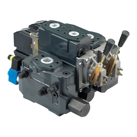
Danfoss PVG 120 Service Manual
Proportional valve group
Hide thumbs
Also See for PVG 120:
- Technical information (48 pages) ,
- Installation manual (9 pages) ,
- Technical information (36 pages)

Related Manuals for Danfoss PVG 120


Summary of Contents for Danfoss PVG 120
- Page 1 MAKING MODERN LIVING POSSIBLE Service Manual Proportional Valve Group PVG 120 powersolutions.danfoss.com...
- Page 2 PVG 120 Proportional Valve Group Revision history Table of revisions Date Changed May 2014 Converted to Danfoss layout – DITA CMS, major revision Jan 2012 Pos. 3 change Feb 2011 Table on page 35 changed, layout changes - all pages Feb 2010...
-
Page 3: Table Of Contents
PVM, Mechanical Activating Module............................31 PVMD and PVH PVMD, Cover for PVM and PVH, Hydraulic Activation...................... 33 PVGI PVGI, Interface for PVG 120 and PVG 32..........................34 PVEH and PVEO PVEH and PVEO, Electrical Activating Module, ON-OFF....................35 PVT, Tank Side Module – Upper Part............................37 PVT, Tank Side Module –... - Page 4 Service Manual PVG 120 Proportional Valve Group Contents Ordering of modules for oil flow exceeding 180 l/min [47.6 US gal/min]..............48 Order Form....................................... 48 Reordering....................................49 520L0247 • Rev JA • May 2014...
-
Page 5: Pvg 120 Service Parts Exploded View
Service Manual PVG 120 Proportional Valve Group PVG 120 service parts exploded view PVG 120 service parts exploded view V310144.A 520L0247 • Rev JA • May 2014... -
Page 6: Pvg 120 Sectional View
Service Manual PVG 120 Proportional Valve Group PVG 120 sectional view PVG 120 sectional view V310100.A Legend: 1 – Main spool 7 – Shock and suction valve PVLP 2 – Pressure adjustment spool in PVP 8 – Suction valve PVLA 3 –... -
Page 7: Safety In Application
Service Manual PVG 120 Proportional Valve Group Safety in application All makes and all types of control valves (incl. proportional valves) can fail, thus the necessary protection against the serious consequences of function failure should always be built into the system. For each application an assessment should be made for the consequences of pressure failure and uncontrolled or blocked movements. -
Page 8: Control System Example
Service Manual PVG 120 Proportional Valve Group Safety in application Control system example Example of a control system for manlift using PVE Fault monitoring input signals and signals from external sensors to ensure the PLUS+1® main controllers correct function of the manlift. - Page 9 • PVPP, pilot oil supply shut off • External cartridge valve connecting LS pressure or main pressure to tank PVG 120 – pump disconnect / block for variable pumps: • PVPE, full flow dump for the PVG 120 • External cartridge valve connecting LS pressure to tank...
-
Page 10: Examples Of Wiring Block Diagram
Service Manual PVG 120 Proportional Valve Group Safety in application Examples of wiring block diagram Example of a typical wiring block diagram using PVEH with neutral power off switch and fault monitoring output for hydraulic deactivation. Emergency Man present stop... - Page 11 Service Manual PVG 120 Proportional Valve Group Safety in application Example of fault monitoring for deactivation of the hydraulic system with extra fault inputs using the PVE’s with DI (Direction Indication) function. Emergency Man present Stop switch PVE 1 Neutral detection / Supply control...
-
Page 12: Identification
Service Manual PVG 120 Proportional Valve Group Identification Identification PVG 120 Identification PVEH PVEO PVMD V310156.A C: PVG – number, week and year of installation D: PVP – pressure setting E: PVP – number, week, year and day manufacturing, issue and series No. -
Page 13: Installation
Service Manual PVG 120 Proportional Valve Group Installation Installation and plug orientation Installation Dimensions 60 Nm 60 Nm [530 lbf•in] [530 lbf•in] 4xM12x18 [4x7/16-14UNCx0.7] V310179.A * Room for dismantling Module of PVB L mm L in 6.61 9.25 11.88 14.53 17.17... -
Page 14: Oil Flow Direction
Service Manual PVG 120 Proportional Valve Group Installation Oil flow direction Mechanical / electrical actuation Mechanical / hydraulic actuation V310169.A V310163.A V310162.A V310170.A Tightening Torques Max. tightening torques – Connection Threads Type G (ISO 228/1) Max. tightening torques Ports PA, PB... - Page 15 Service Manual PVG 120 Proportional Valve Group Installation Max. tightening torques – Mounting Threads in SAE J 518c Flanges Port Size Threads Tightening torque 1 in M12, 18 deep 68 N•m 7/16 - 14 UNC 0.7” deep [600 lbf·in] 3/4 in M10, 17 deep 45 N•m...
-
Page 16: Pvm, Lever Positions
Service Manual PVG 120 Proportional Valve Group Installation PVM, Lever Positions Base with an angle of 37.5° Base with an angle of 22.5° V310018.A V310014.A Setting of max. flow Setting of Max. Flow max.A max.B max. max. 3[0.12] max.B 8 Nm [70 lbf in] max.A... -
Page 17: Pressure Setting
Service Manual PVG 120 Proportional Valve Group Installation Pressure Setting PVP, LS Relief Valve Pressure Setting PVP, LS Relief Valve Setting 360° ~ 130 bar [360° ~ 1900 psi] 3 Nm 35 Nm 8[0.31] [27 lbf•in] [310 lbf•in] V310102.A PVB, LS Relief Valve Pressure Setting PVB, LS Relief Valve Setting 360°... -
Page 18: Option, Oil Flow Direction And Setting Of Max Flow
For security reasons, any replacement of O-rings between valve block 1 and intermediate plate 2 may only be effected at service shops authorized by Danfoss. Caution Mixing up PVE series 2 for PVG 120 may lead to self-actuation. 520L0247 • Rev JA • May 2014... - Page 19 Service Manual PVG 120 Proportional Valve Group Installation PVEH, PVEO 520L0247 • Rev JA • May 2014...
-
Page 20: Bleeding
Service Manual PVG 120 Proportional Valve Group Installation Bleeding PVG 120 installed vertically V310105.A If the group is installed vertically, it is recommended to bleed it at the adjusting screws. PVPE/PVH relief valves Max. tightening torque for PVPE/PVH Position Across flats Max. -
Page 21: Pvph And Ls Connections
Service Manual PVG 120 Proportional Valve Group Installation PVPH and LS connections Max. tightening torque for PVPH and LS Max. tightening torque Sealing Threads, DS/ISO 228/1 Steel washer PVPH: G ¼ 40 Nm [350 lbf·in] LS: G ∕ 60 Nm [530 lbf·in] Cupper washer PVPH: G ¼... -
Page 22: Connection Pvpe
Service Manual PVG 120 Proportional Valve Group Installation Connection PVPE Installing the wire When installing the wire remember to connect the built-in diode to the plug pins. 520L0247 • Rev JA • May 2014... -
Page 23: Pvp
Service Manual PVG 120 Proportional Valve Group PVP, Pump Side Module 520L0247 • Rev JA • May 2014... - Page 24 Service Manual PVG 120 Proportional Valve Group With O-ring Boss port connection 1 in - 12 UN Code No. PVP – closed center incl. PVPD 155G5022 PVP – open center excl. PVPD, PVPH, PVPE 155G5023 PVP – open center incl. uprating kit excl. PVPD, PVPH, PVPE 155G5028 PVP –...
-
Page 25: Pvpd, Pvph, Pvpe, Accessories For Pvp
Service Manual PVG 120 Proportional Valve Group PVPD, PVPH, PVPE, Accessories for PVP 520L0247 • Rev JA • May 2014... - Page 26 Service Manual PVG 120 Proportional Valve Group Additional Module for PVP Open Center Type Code No. 12 V 155G5052 PVPE – extra electrical relief valve 24 V 155G5054 PVPD – Plug 155G5041 PVPH – extra hydraulic relief valve 155G5061 Item Description Code No.
-
Page 27: Pvlp / Pvla
Service Manual PVG 120 Proportional Valve Group PVLP / PVLA PVLP / PVLA, Shock and Suction Valve Port A/B 520L0247 • Rev JA • May 2014... - Page 28 Service Manual PVG 120 Proportional Valve Group PVLP / PVLA Type Code No. PVLP, pressure setting: 50, 75, 100, 125, 175, 200, 225, 250, 275, 300, 325, 350 , 375, 400 bar [725, 1087, 1450, 1813, 2538, 2900, 3263, 3625, 3988, 4351, 4713, 155G0...
-
Page 29: Pvbp, Pvbr, Pvbc, Pvbu
Service Manual PVG 120 Proportional Valve Group PVBP, PVBR, PVBC, PVBU PVBP, PVBR, PVBC, PVBU Accessories for PVB 520L0247 • Rev JA • May 2014... - Page 30 Service Manual PVG 120 Proportional Valve Group PVBP, PVBR, PVBC, PVBU Type Code No. PVBU - uprating kit for PVB 155G6035 PVBR - LSA/B relief valve 155G6080 PVBP - plug 155G6081 PVBC - connection for external LS-signal 155G6082 Item Description Code No.
-
Page 31: Pvm
Service Manual PVG 120 Proportional Valve Group PVM, Mechanical Activating Module 8±1 Nm [70±10 lbf•in] 5[0.20] 8±1 Nm [71±9 lbf•in] 3[0.12] 10[0.39] 2.5±1 Nm [22±9 lbf•in] 8±1Nm [70±9 lbf•in] 4 mm [0.12 in] 5[0.20] 8± 0.5 Nm [70±4.5 lbf•in] 8±1 Nm [70±9 lbf•in]... - Page 32 Service Manual PVG 120 Proportional Valve Group Type Code No. PVM with PVMD or PVE 22.5° / 37.5° 155G3040 PVM with PVH 22.5° / 37.5° 155G3050 Item Description Code No. Handle, black knob, including nut Base, including set screw 22.5° / 37.5°...
-
Page 33: Pvmd And Pvh
Service Manual PVG 120 Proportional Valve Group PVMD and PVH PVMD, Cover for PVM and PVH, Hydraulic Activation Type Code No. PVM + PVH assy - UNF 155G4021 PVH assy - BSP.F - thread 155G4022 PVMD assy 155G4061 Item Description Code No. -
Page 34: Pvgi
Service Manual PVG 120 Proportional Valve Group PVGI PVGI, Interface for PVG 120 and PVG 32 Type Code No. 155G7033 PVGI sddy 1 in - 12 UN 155G7031 in - 16 UNC 155G7032 Item Description Code No. Combination module –... -
Page 35: Pveh And Pveo
Service Manual PVG 120 Proportional Valve Group PVEH and PVEO PVEH and PVEO, Electrical Activating Module, ON-OFF 520L0247 • Rev JA • May 2014... - Page 36 Service Manual PVG 120 Proportional Valve Group PVEH and PVEO Type Connector Code No. Hirschman 155G4092 Fault monitoring active, 11-32V 155G4094 PVEH Hirschman 155G4093 Fault monitoring passive, 11-32V 155G4095 155G4272 Hirschman 155G4274 PVEO 155G4282 155G4284 Item Description Code No. El. plug DIN 43650 Black PG 9...
-
Page 37: Pvt
Service Manual PVG 120 Proportional Valve Group PVT, Tank Side Module – Upper Part 520L0247 • Rev JA • May 2014... - Page 38 Service Manual PVG 120 Proportional Valve Group With LX-connection Code No. PVT, SAE UNF, mounting thread in - 16 UNC 155G7025 PVT, Boss port connection 1 in - 12 UN 155G7024 × 23 deep 155G7023 Without LX-connection Code No. PVT, SAE UNF, mounting thread...
-
Page 39: Pvt, Tank Side Module - Lower Part
Service Manual PVG 120 Proportional Valve Group PVT, Tank Side Module – Lower Part 520L0247 • Rev JA • May 2014... - Page 40 Service Manual PVG 120 Proportional Valve Group Code No. PVT with pilot supply for PVE 155G7042 PVT without pilot supply for PVE 155G7062 BSP.F. thread Code No. PVT with pilot supply for PVE 155G7040 PVT without pilot supply for PVE...
-
Page 41: Pvas And Pvgi
Service Manual PVG 120 Proportional Valve Group PVAS and PVGI PVGI, Assembly Kit PVAS, Assembly Kit Asssembly sequence 1. Mount nut on short thread and torque 10 N•m 2. Mount seal 3. Assemble PVG 4. Mount seal and nut on long thread and torque 10 N•m 5. - Page 42 Service Manual PVG 120 Proportional Valve Group PVAS and PVGI PVGI, Assembly Kit (continued) Type Code No. PVGI for 0 basic module 155G8040 PVGI for 1 basic module 155G8041 PVGI for 2 basic module 155G8042 PVGI for 3 basic module...
-
Page 43: Set Of Seals
Service Manual PVG 120 Proportional Valve Group Set of seals Set of Seals Type Code No. 155G8501 PVB / PVB additional module 155G8502 PVPH 155G8526 PVPE 155G8527 PVLP / PVLA 155G8525 155G8518 PVEH / PVEO 155G8519 PVH / PVMD 155G8505... -
Page 44: Pvg 120 Modules Selection Chart
Service Manual PVG 120 Proportional Valve Group PVG 120 Modules Selection Chart PVG 120 module selection chart PVG 120 modules exploded view V310173.A PVB, high basic module O-ring Metric flange Weight flange Boss kg [lb] Facilities for shock valves AB... - Page 45 Service Manual PVG 120 Proportional Valve Group PVG 120 Modules Selection Chart Accessory modules for PVB Code number Weight, kg [lb] Plug, PVBP 155G6081 0.4 [0.9] press. relief valve, PVBR 155G6080 External LS connection, PVBC 155G6082 Module for oil flow > 180 l/min [47.6 US gal/min], PVBU...
- Page 46 Service Manual PVG 120 Proportional Valve Group PVG 120 Modules Selection Chart PVP, pump side module Code number O-ring Metric flange Weight Boss flange kg [lb] Open Excl. PVPD, PVPH, PVPE 155G5023 155G5037 155G5021 10.0 [22.1] centre For PVB-oil flow > 180 l/min [47.6...
- Page 47 Service Manual PVG 120 Proportional Valve Group PVG 120 Modules Selection Chart PVLP, shock and suction valve A/B (continued) Pressure setting 2550 155G0175 2900 155G0200 3250 155G0225 3650 155G0250 4000 155G0275 4350 155G0300 4700 155G0325 5100 155G0350 5400 155G0375 5800 155G0400 0.175 [0.386]...
-
Page 48: Ordering Of Modules For Oil Flow Exceeding 180 L/Min [47.6 Us Gal/Min]
The code number of the spring and plug is 155G6035 (PVBU, accessory module). Order Form An order form for PVG 120 hydraulic valve is shown on next page. The form can be obtained from the Danfoss Power Solutions Sales Organisation. -
Page 49: Reordering
Reordering The space at the top right-hand corner of the form is for Danfoss to fill in. The code number for the whole of the specified valve group (PVG No.) is entered here. In the event of a repeat order all you have to do is enter the number Danfoss has given on the initial confirmation of order. - Page 50 Service Manual PVG 120 Proportional Valve Group Order specification 520L0247 • Rev JA • May 2014...
Need help?
Do you have a question about the PVG 120 and is the answer not in the manual?
Questions and answers