
Subscribe to Our Youtube Channel
Related Manuals for UVITEC Cambridge FIREREADER MAX

Summary of Contents for UVITEC Cambridge FIREREADER MAX
- Page 1 F F F F R R R R EADER EADER EADER EADER S E R & S E R V I C E M A N U A L 07//2012-index j UVITEC – Cambridge 1/225...
- Page 2 Please read me first! Please read carefully the installation instruction before proceeding to the installation. Please do not connect the FIREREADER USB camera to the computer before installing the FireReader 1D software. After the software is fully installed, connect the FireReader USB camera to the computer.
- Page 3 WARNNING : during the use of this material, the non-respect of these instruction can cause very serious burns to the user. WARNING : Ultra Violet light is dangerous for unprotected eyes and skin, therefore the user must wear UV protective goggles (Ref. LP70) or a face-shield (Ref.MP-80 or MP-800) SAVE THESE INSTRUCTIONS AVISO: Durante el uso del instrumento, no seguir las instrucciones puede causar quemaduras graves al usuario.PRECAUCION : La radiación ultravioleta puede ser peligrosa para los ojos y la piel expuestos sin...
- Page 4 UVITEC Cambridge is dedicated to your satisfaction and we will be pleased to answer any question you may have. We are also very receptive to your suggestions. Many of the new features and enhancements in this system are a direct result of conversations with our customers.
-
Page 5: Table Of Contents
FIREREADER FIREREADER FIREREADER FIREREADER SERIES SERIES SERIES SERIES S E R & S E R V I C E M A N U A L Table of content INTRODUCTION ................................9 WARNING, SAFETY, LICENSE AGREEMENT .........................10 End user license agreement ............................12 COMPUTER CONFIGURATION ............................14 Minimum computer configuration - FireReader ....................... - Page 6 EXPOSURE MENU ..............................44 Access to the Exposure modules ..........................44 Auto-exposure ................................46 Manual exposure ..............................49 Serial exposure ................................52 Focus point adjustment and motorized zoom controls ..................... 54 ANALYSIS MENU ................................56 Access to the analysis modules ..........................56 ..........................58 OLECULAR WEIGHT ANALYSIS MODULE Objectives and output ..............................58...
- Page 7 Positive / negative ..............................154 Reset ..................................154 PROCESSING MENU ..............................156 Access to the Processing module ..........................156 Merge marker ................................. 158 Paste marker ................................161 Multiplex images ..............................164 Bioluminescence ..............................166 Subtract image ................................ 169 Subtract background............................... 171 Apply flat field .................................
- Page 8 General advices ............................... 221 Spare parts – FireReader series ..........................221 WARRANTY ................................223 CONFORMITY ................................225 UVITEC – Cambridge 8/225...
-
Page 9: Introduction
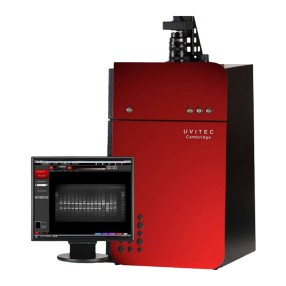
FIREREADER FIREREADER FIREREADER FIREREADER SERIES SERIES SERIES SERIES N T R O D U C T I O N About is an image acquisition system dedicated to the capture of fluorescence gel images. EADER offers exquisite precision and resolution, which mean reliable results for both quantification and EADER documentation. -
Page 10: Warning, Safety, License Agreement
FIREREADER FIREREADER FIREREADER FIREREADER SERIES SERIES SERIES SERIES A R N I N G A F E T Y I C E N S E A G R E E M E N T Please read carefully these instructions before installing and operating the FIREREADER-1D software Whenever you find this pictograph, be sure to refer to this Manual. - Page 11 obligatory protection. It is mandatory to power down the system and to disconnect the AC main from the unit before performing any disassembly or repair the instrument. The system must be unplugged from the AC voltage outlet if it is not intended to use it before a long time.
-
Page 12: End User License Agreement
All the equipment connected to this unit shall be certified according to standard IEC 950, or other IEC/ISO Standards applicable to the equipment This instrument must be used only by specialized personnel that know the health risks associated with UV radiation and with the reagents that are normally used with this instrument. - Page 13 portable computer (other than a network server) and one person uses that computer more than 80% of the time, then that person may also use the Software on a 2nd computer for the purpose of viewing and post-processing images. Title We remain the owner of all right, title and interest in the Software and Documentation.
-
Page 14: Computer Configuration
FIREREADER FIREREADER FIREREADER FIREREADER SERIES SERIES SERIES SERIES O M P U T E R C O N F I G U R A T I O N Minimum computer configuration - FireReader Minimum requirement PCI bus (Intel chipset) supporting bus mastering mode Minimum front side bus speed: 1,333GHz Processor Intel Core 2 Duo... -
Page 15: Installing The Firereader
FIREREADER FIREREADER FIREREADER FIREREADER SERIES SERIES SERIES SERIES N S T A L L I N G T H E I R E E A D E R Unpacking the system Please, open the F box carefully and verify the contents: EADER Darkroom / Camera and camera support Power cable... - Page 16 Please keep an open area of at least 20 cm at the rear of the cabinet to ensure a proper air circulation for the system. The system should be located in an area free of excessive dust or moisture, strong magnetic fields or ionising radiation. It is also recommended that the ambient temperature be stable and within the range of 15°C to 25°C (20°C recommended) and that the relative humidity not exceed 70%, non- condensing.
-
Page 17: Installing The Hardware
Installing the hardware Please read carefully the installation instruction before proceeding to the installation. Please do not connect the FIREREADER USB camera to the computer before installing the FireReader 1D software. After the software is fully installed, connect the F USB camera to the EADER computer. - Page 18 Illustration 2: the camera/optics installed on the top of the darkroom (rear side) Illustration 3: the camera/optics installed on the top of the darkroom (front side) UVITEC – Cambridge 18/225...
-
Page 19: Firereader 1D Software Installation
FIREREADER FIREREADER FIREREADER FIREREADER SERIES SERIES SERIES SERIES I R E E A D E R S O F T W A R E I N S T A L L A T I O N Pre-requirement Please read carefully the installation instruction before proceeding to the installation. Please do not connect the FIREREADER USB camera to the computer before installing the FireReader 1D software. -
Page 20: Windows Xp And Vista Warning
Windows XP and Vista warning At computer startup, Windows pop-ups the “found new hardware wizard” box. Press “Cancel” button before starting the installation. Software installation Please ensure the FireReader system is switched-off before the software installation. Do not switch on the system before the installation is fully completed. Step 1 Insert the CD-ROM in the CD-ROM drive Ensure that all other application programs are closed. - Page 21 Please click on the Install software icon. A pop-up window displays the following Windows installation authorization message: Click on the “Install” button. The setup wizard will then start to initialize. This could take up to 1 minute: The setup wizard will then start the installation process: UVITEC –...
- Page 22 Step 2. The welcome screen is displayed, click on NEXT to continue Click on NEXT to continue Select the Destination directory (“c:\Program files\Uvitec\Alliance” by default). Then click on NEXT. Program files are installed in the specified directory and group created: UVITEC –...
- Page 23 When the software installation is complete, click on Finish. The system will then start the driver installation process. The setup wizard will then install the USB controller driver. Click on Install to install the system’s USB driver. UVITEC – Cambridge 23/225...
- Page 24 When finished, click on OK. A pop-up window displays the following camera driver installation message: Click Next to continue. The following messages are then successively displayed: A pop-up window displays the following security message: Windows 7: Select the “Install” option. Windows XP: UVITEC –...
- Page 25 Select the “Continue Anyway” option. The following message is then displayed: Once the software is installed, the system is updated. This can take a few minutes, depending on the computer speed. When the set-up is completed, restart your computer. After the restart, switch on the FireReader system. Keep the FireReader 1D CD-Rom in the CD-Rom drive of your computer.
-
Page 26: Connecting The Camera
Connecting the camera CAUTION You must first connect the darkroom and the computer to Earth Plug the darkroom into an earthed socket. Plug the computer and the monitor into an earthed socket. 1- Connect the camera USB cable to the computer USB port (rear side). 1: USB CAMERA CONNECTION Computer rear side - Connection... -
Page 27: Connecting The Darkroom - Auto Motorized Zoom Series Only
Connecting the darkroom – Auto motorized zoom series only Auto Motorised zoom series only 2- Connect the USB cable from the darkroom to the computer USB port. 1: Z (X-P OOM CONNECTION RESS SERIES ONLY WITH MOTORISED ZOOM LENS 1 – Z OOM TO THE DARKROOM Cable from the zoom lens Darkroom rear side... - Page 28 Darkroom back side– USB cable connection Computer rear side – USB cable connection It is mandatory to connect the system to an appropriate AC voltage outlet that is properly grounded and protected by a circuit breaker. Connecting to ground constitutes an obligatory protection.
-
Page 29: Upgrading The Software
Upgrading the software WARNING Before to install a new software version, make sure you have the CD-Rom of the current software version you are using First, uninstall the previous version of the software using the uninstall shield. To do so, click on the Windows Start button, select the UviTec directory and clik on UnInstFireReader 1D: Follow the uninstall instruction. -
Page 30: Darkroom Control Board Driver Installation
Darkroom control board driver installation Darkroom connection The USB port electrically supplies the motorized lens and the darkroom. To this extent, only the USB zoom should be connected to the computer rear side USB hub. The USB cable should be connected to the rear side USB port of the computer. - Page 31 Select the CD-Rom media drive and click on Next: A dialog box indicating that this driver has not passed the Windows Logo testing is displayed. Even though our driver works on Windows XP, it is not numerically signed, so click on « Continue anyway » button to continue the installation.
-
Page 32: Trouble Shooting - Windows Device Manager
Trouble shooting – Windows device manager In case of installation issue, we recommend to check the driver status using the Windows Device Manager. To do so, from the Windows start menu, select “Control Panel”. The software opens the Windows setting options; For Windows 7, select System and security, then system, then Device Manager: UVITEC –... - Page 33 The Device Manager should appear as below for the FireReader and SL4 USB series: UVITEC – Cambridge 33/225...
-
Page 34: Using The Darkroom
FIREREADER FIREREADER FIREREADER FIREREADER SERIES SERIES SERIES SERIES S I N G T H E D A R K R O O M Warning while using the darkroom WARNING The transilluminator is used for the fluorescence applications. WARNING The use of the FireReader involves ultraviolet (UV) illumination. Proper precautions must be taken to avoid eye and skin exposure to the UV light. -
Page 35: Control Panel - Firereader D56 & D59 Series
Control panel – FireReader D56 & D59 series Main switch The darkroom D56 & D59 main switch is located on the darkroom right hand side: « POWER» switch Darkroom right hand side Switch on the main switch before to use the system. USB board Optional : for Auto versions... - Page 36 D59 darkroom – Epi UV & WL Epi 254nm Epi 365nm Visible white UV table Door security light switch switch switch switch switch UV epi-illumination Select the appropriate wavelength: 254 or 365nm. Switch on the epi-UV lamp by pushing the corresponding button to the position [I], the control panel diode will light on.
- Page 37 D56 & D59 darkroom – Epi WL Visible white UV table Door security light switch switch switch White light epi-illumination Switch on the white light lamp by switching the white light command to the position [I], the control panel diode will light on. After use, switch off the light by putting the switch to the position [0]. Transilluminator Case 1: security on when the door is open Switch on the door security switch to the “0”...
- Page 38 Filter wheel The 6 positions filter wheel is supplied with the F590 M58 interferential filter supplied with the system for ethidium bromide application. The F590 filter is already installed on the first position of the wheel. To select the filters, turn the black handle and select the position of your choice. The first position is designed for the F590 filter for ethidium bromide application.
- Page 39 WARNING You have to protect your eyes and your skin. You can open the door, the UV table and UV lamp will continue to work. You must wear all possible UV protection, especially for your eyes, when the transilluminator switch is turned ON. Mask and gloves are recommended to block the UV radiation.
-
Page 40: Quick Start
FIREREADER FIREREADER FIREREADER FIREREADER SERIES SERIES SERIES SERIES U I C K S T A R T Taking your first picture This Quick start is intended as a quick reference guide for acquisition. For more detailed information on the individual features reference the appropriate part of this manual. Power on the computer. - Page 41 1- Select your Application in the upper part of the menu. Click on OK to validate your selection. Click on Start exposure. If necessary, adjust the exposure time. Then click on Stop exposure. After the exposure is over, save the image UVITEC –...
-
Page 42: Navigating The Firereader 1D Software
FIREREADER FIREREADER FIREREADER FIREREADER SERIES SERIES SERIES SERIES A V I G A T I N G T H E I R E E A D E R S O F T W A R E Access to the Exposure modules The FireReader 1D software opens with the following image window: The FireReader-1D operating environment is organized into five areas: The menu bar:... - Page 43 The folder menu: The image window: UVITEC – Cambridge 43/225...
-
Page 44: Exposure Menu
FIREREADER FIREREADER FIREREADER FIREREADER SERIES SERIES SERIES SERIES X P O S U R E M E N U Access to the Exposure modules Select the Exposure module from the menu bar to access the Exposure menu: This will open the Exposure function folder: The Exposure function folders contain the following features: UVITEC –... - Page 45 Define automatically an ideal exposure time Set your own exposure time Take several images and select the one you prefer. UVITEC – Cambridge 45/225...
-
Page 46: Auto-Exposure
Auto-exposure The FireReader system can calculate automatically an ideal exposure time (Auto-exposure) taking into account the Application protocol pre-defined parameters. When you select the Auto-Exposure option, the system samples the light levels and uses the values to calculate the final exposure time. Click on the “Auto-exposure”... - Page 47 The factory settings include 3 pre-defined Application protocols: SafeLight UV fluorescence Conversion screen You can also create or select your own Application protocol. Please refer to the Application protocol chapter of this manual to have more details on the way you can create your own Application. 2- Click on Start Exposure.
- Page 48 changed independently from the Application protocol. To proceed, click on the Set-up button. This will open the set-up menu window: Sensitivity This option defines the image sensitivity for your image exposure. The FireReader systems offer exquisite resolution and sensitivity to maximize quantifiable data. The system can be used at either its full resolution or with binning.
-
Page 49: Manual Exposure
Manual exposure The exposure time is the acquisition of an image by summing the signal of the camera during the time displayed under integration time button. The exposure time process will take into account the Application protocol pre-defined parameters. Click on the “Manual exposure” button. A window displays the following menu: Start exposure To proceed: 1- Select your application protocol from the application menu... - Page 50 The factory settings include 3 pre-defined Application protocols: SafeLight UV fluorescence Conversion screen You can also create or select your own Application protocol. Please refer to the Application protocol chapter of this manual to have more details on the way you can create your own Application. 2- Click on Start Exposure.
- Page 51 The stop function captures the last image for further saving, analysis or enhancement. To proceed, click on the stop preview button. Set-up The Set-up button gives you access to the main exposure parameters. These parameters could be changed independently from the Application protocol. To proceed, click on the Set-up button.
-
Page 52: Serial Exposure
Serial exposure The Serial exposure mode allows repetitive image acquisition with or without image accumulation. You can then select the image you prefer from the series of images. Click on the “Serial exposure” button. A window displays the following menu: Start exposure To proceed: 1- Select your application protocol from the application menu... - Page 53 The factory settings include 3 pre-defined Application protocols: SafeLight UV fluorescence Conversion screen You can also create or select your own Application protocol. Please refer to the Application protocol chapter of this manual to have more details on the way you can create your own Application. 2- Click on Start Exposure.
-
Page 54: Focus Point Adjustment And Motorized Zoom Controls
The stop function captures the last image for further saving, analysis or enhancement. To proceed, click on the stop preview button. Set-up The Set-up button gives you access to the main exposure parameters. These parameters could be changed independently from the Application protocol. To proceed, click on the Set-up button. - Page 55 All cameras require a focus point adjustment. In order to proceed, you have to zoom to the maximum on a straight forward image (a printed paper, a business card ...). Then, focus till you obtain a very sharp image on the screen. This procedure can be done with epi-illumination light and a printed paper.
-
Page 56: Analysis Menu
FIREREADER FIREREADER SERIES SERIES FIREREADER FIREREADER SERIES SERIES N A L Y S I S M E N U Access to the analysis modules Select the Analysis module from the menu bar to access the Exposure menu: This will open the analysis function folder: Select the Molecular weight icon to open the molecular weight analysis (MW) module UVITEC –... - Page 57 Select the Colony counting icon to open the colony counting (CC) analysis module Select the Optical density - 1D icon to open the optical density (OD) analysis module based on a 1D detection Select the Distance calculation module to measure the distance in between a front line and an ending line UVITEC –...
-
Page 58: Molecular Weight Analysis Module
FIREREADER FIREREADER FIREREADER FIREREADER SERIES SERIES SERIES SERIES O L E C U L A R W E I G H T A N A L Y S I S M O D U L E Objectives and output The FireReader 1D Molecular Weight module features the calculation of electrophoretic distances according to markers or standards: in molecular weight (unit: KiloDalton) -
Page 59: Molecular Weight Module (Mw) Operating Environment
Molecular weight module (MW) operating environment The MW module opens on the following window: The FireReader 1D operating environment is organized into four areas: The dash board The image window The working window The dash board contains five different tabs: 1. - Page 60 It also contains the image toolbar: Print the image Set the band parameters (white bands / black background ; black bands/ white background) Copy to clipboard Display the molecular weight on the image Change the image display parameters Autoscale Zoom in or out the image The working window displays the graphs and tables related to the active analysis: UVITEC –...
- Page 61 It also contains the working window image toolbar: Print the image Copy to clipboard Export the table to Microsoft Excel UVITEC – Cambridge 61/225...
-
Page 62: Toolbar In Details
Toolbar in details Print Click on the “Print” icon to print the image, the table or the graphs. A pop-up window displays the Print preview: The Print preview displays a preview of the image, as it will be printed. Click on Print to validate the preview. A pop-up window displays the following menu: Select a printer Click on Properties to modify the default setting of the printer, if necessary Select the number of copies... - Page 63 Black / White bands This function set the bands parameters (white bands / black background / black bands, white background). 1. To proceed, click on the Black/White bands icon. A pop-up window displays the following menu: You can select the following options: Automatic detection.
- Page 64 Display the molecular weight 1. Click on the “display the molecular weight” to display the calculated molecular weight on top of the image. Molecular weight displayed on the image Default display Image display 1. Click on the “Image display” to displays the Image Master data as well as the Image Display set-up.
- Page 65 can only display 8-bit images (256 grey levels). Due to this limitation, the FireReader 1D software handles two images: A “memory” image corresponding to the 12, 14 or 16-bit format (4 096, 16 384 or 65 536 grey levels) A “display image” corresponding to the image displayed on the screen (256 grey levels) The easiest way to calculate the “display image”...
- Page 66 Before After A saturated image is inappropriate for image quantification with image analysis software. The saturation option allows you to visualise in red, pixels that have the maximum grey level (4095 for a 12-bit image or 16 383 for a 14-bit image or 65536 for a 16-bit image) in order to avoid to flatten the peaks.
- Page 67 Original image Multicolored painted image Original image Red painted image Autofit 1. Click on the “Autofit” to resize the image to fit the size of the monitor. The Autofit feature proportions the display of the image to the screen resolution Auto-scale (no scroll bar) No auto-scale (scroll bar) UVITEC –...
- Page 68 Zoom 1. Click on the “+” or “-“ to zoom in or out the image Zoom 150% Auto-scale (no zoom) Excel This function transfers the results table to Microsoft Excel 1. To proceed, click on the Send to Excel icon. The Excel software is automatically opened by the FireReader-FireReader 1D and the table is transferred to Excel UVITEC –...
-
Page 69: E T E C T
1 - D E T E C T A – Edit lane The molecular weight module opens on the Edit lane dashboard of the Detect process: The dashboard details the lane edition parameters: Lane direction Number of lanes Gap between the lanes REA OF INTEREST On the image, click and drag to define the analysis area and to overlap the lanes. - Page 70 The lanes are defined by green lines, overlaid on the gel image. The gel area is surrounded by square anchors: To resize the entire lane frame, drag an anchor point in or out. The opposite anchor point will remain fixed while the frame expands or contracts. The frame will expand or contract from the center.
- Page 71 The lane direction is automatically modified on the image. UMBER OF LANES Select the number of lanes: The number of lane is automatically modified on the image. AP BETWEEN THE LANES Define the gap between the lanes: Short gap Large gap The gap between the lanes is automatically modified on the image.
- Page 72 ELP MENU Click on the “Help” button. You automatically access the user manual at the chapter corresponding to the function UVITEC – Cambridge 72/225...
-
Page 73: B - Edit Band
B – Edit band The Edit band process follows the lane definition: The edit band process automatically identifies all the bands for the defined lanes. You can also manually mark the bands on the image or on the lane’s profile. All bands will be automatically detected when you first access the band detection process, based on default parameters. - Page 74 AND DETECTION ON THE PROFILE The profile is calculated based on the average intensity of each row of pixels across the specified width of the lane. A lane profile provides a visualisation of the intensity of the bands. Bands are represented by peaks. You can add or remove bands by clicking directly on the profile.
- Page 75 Note: For arrow cursor, the band is added at the cursor position. For rectangular cursor, the band is added at the highest position within cursor bounds. ISUALISATION OF THE PROFILES In the profile parameter window, you can select the lanes’ profile to be displayed. To do so, just click on the profile name to select or unselect the profiles.
- Page 76 ELP MENU Click on the “Help” button. You automatically access the user manual at the chapter corresponding to the function UVITEC – Cambridge 76/225...
-
Page 77: C - Add Marker Values
C – Add marker values The marker values process follows the band detection. This function allows the assignment of the molecular weight marker’s values to the bands of the marker lane. Note: you can either access marker value menu by clicking on the next button of the band detection or directly on marker value tab. - Page 78 Browse to specify the marker directory Double click on the file name you want to load REATE A MARKER 1. Click on the “Create a marker” button to create marker’s values. Type your values, band to band, in a descending order. The OK button validates your data. Note: A minimum of four values is necessary to validate the data.
- Page 79 The migration curve is automatically displayed next to the lane’s profile: The migration curve allows to check the detection of value application errors, distortion errors, bad separation between the bands, or the quality of the standard itself. Note: To delete the wrong data, you can either place the cursor arrow on the wrong value itself and click on it, or go for the manual assignment.
- Page 80 The “Next” button validates your parameter and opens the following analysis step. C – Add marker 2- Analyse - MW values A- results The “Back” button validates your parameter and opens the following analysis step. C – Marker values B- Band detection PTION FOLDER The option folder gathers the following functions: Help...
- Page 81 DIT THE MARKER VALUES 1. Click on the “Edit the marker values” button. 2. A pop-up window displays the following menu on which you can modify the marker values: You can add, remove, and save your marker values; ELP MENU Click on the “Help”...
-
Page 82: O L E C U L A R W E I G H T
2 - A – M N A L Y S E O L E C U L A R W E I G H T A – Molecular weight results The molecular weight results process follows the marker’s value assignment. Note: you can either access the molecular weight results by clicking on the next button of the marker’s value assignment or directly by clicking on the Molecular weight tab of the 2-Analyse-MW folder. -
Page 83: Return To The 1D Acquisition Module
PTION FOLDER The option folder gathers the following functions: Help ELP MENU Click on the “Help” button. You automatically access the user manual at the chapter corresponding to the function Return to the 1D acquisition module To return to the 1D acquisition module, select Home Exit from the dash menu. UVITEC –... -
Page 84: Colony Counting Analysis Module
FIREREADER FIREREADER FIREREADER FIREREADER SERIES SERIES SERIES SERIES O L O N Y C O U N T I N G A N A L Y S I S M O D U L E Objectives and output The FireReader 1D Colony counting module features the calculation of the number of colonies and their characteristics (Automatic colony counting) or the manual counting of colonies with the mouse (Manual colony counting). -
Page 85: Colony Counting (Cc) Module Operating Environment
Colony counting (CC) module operating environment The Colony counting module opens on the following window: The FireReader 1D operating environment is organised into three areas: 1. The dash board 2. The image window 3. The working window The dash board contains 3 different tabs: 1. - Page 86 It also contains the image toolbar: Print the image Set the bands parameters (white bands / black background / black bands, white background) Copy to clipboard Display the colony number on the image Change the image display parameters Autoscale Zoom in or out the image The working window displays the graphs and tables related to the active analysis: UVITEC –...
-
Page 87: Toolbar In Details
It also contains the working window image toolbar: Print the image Copy to clipboard Export the table to Microsoft Excel Toolbar in details Print Click on the “Print” icon to print the image, the table or the graphs. A pop-up window displays the Print preview: The Print preview displays a preview of the image, as it will be printed. - Page 88 Black / White bands This function set the bands parameters (white bands / black background / black bands, white background). To proceed, click on the Black/White bands icon. A pop-up window displays the following menu: You can select the following options: Automatic detection.
- Page 89 Display the colony number Click on the “display the molecular weight” to display the calculated molecular weight on top of the image. Colonies count displayed on the image Default display Image display Click on the “Image display” to displays the Image Master data as well as the Image Display set-up.
- Page 90 Some images has a 12, 14 or 16-bit format and Windows® can only display 8-bit images (256 grey levels). Due to this limitation, the FireReader 1D software handles two images: A “memory” image corresponding to the 12, 14 or 16-bit format (4 096, 16 384 or 65 536 grey levels) A “display image”...
- Page 91 Before After A saturated image is inappropriate for image quantification with image analysis software. The saturation option allows you to visualise in red, pixels that have the maximum grey level (4095 for a 12- bit image or 16 383 for a 14-bit image or 65536 for a 16-bit image) in order to avoid to flatten the peaks.
- Page 92 Original image GFP painted image Original image Multicolored painted image Original image Red painted image Autofit Click on the “Auto-scale” to resize the image to fit the size of the monitor. The Auto-scale feature proportions the display of the image to the screen resolution Auto-scale (no scroll bar) No auto-scale (scroll bar) UVITEC –...
- Page 93 Zoom Click on the “+” or “-“ to zoom in or out the image Zoom 150% Auto-scale (no zoom) Excel This function transfers the results table to Microsoft Excel . To proceed, click on the Send to Excel icon. The Excel software is automatically opened by the FireReader 1D and the table is transferred to Excel UVITEC –...
-
Page 94: A U T O M A T I C C O U N T I N G
U T O M A T I C C O U N T I N G Detection The detection process automatically identifies all the colonies for a defined area of analysis lanes. The colonies will be automatically detected when you first access the automatic counting. -
Page 95: Return To The 1D Acquisition Module
To define a free form, click on the first point of the area on the image. Move the cursor to define one edge of the area. Validate this edge by clicking once. Then, repeats this procedure as many times as necessary. Select the “Square”... -
Page 96: Manual Counting
A N U A L C O U N T I N G Manual counting The manual Colony counting opens on this screen: The dashboard details the manual counting parameters: Left click for green type colonies Right click for red type colonies Reset counting EFT CLICK FOR GREEN TYPE COLONIES Click on the left mouse button to count a green type colony. -
Page 97: Return To The 1D Acquisition Module
Note: you can cancel a counted colony by clicking once again with the right mouse button. ESET COUNTING The “Reset” button restores the counters to zero. PTION FOLDER The option folder gathers the following functions: Help ELP MENU Click on the “Help” button. You automatically access the user manual at the chapter corresponding to the function Return to the 1D acquisition module To return to the 1D acquisition module, select Home Exit from the dash menu. -
Page 98: Istance Calculation Module
FIREREADER FIREREADER SERIES SERIES FIREREADER FIREREADER SERIES SERIES I S T A N C E C A L C U L A T I O N M O D U L E Objectives and output The FireReader 1D Distance module features the calculation of electrophoretic distances according to markers or standards: in R.F. -
Page 99: Distance Calculation Module Operating Environment
Distance calculation module operating environment The Distance module opens on the following window: The FireReader 1D operating environment is organized into four areas: 1. The dash board 2. The image window 3. The working window The dash board contains five different tabs: 1. - Page 100 It also contains the image toolbar: Print the image Set the band parameters (white bands / black background ; black bands/ white background) Copy to clipboard Display the molecular weight on the image Change the image display parameters Autoscale Zoom in or out the image The working window displays the graphs and tables related to the active analysis: UVITEC –...
-
Page 101: Toolbar In Details
It also contains the working window image toolbar: Print the image Copy to clipboard Export the table to Microsoft Excel Toolbar in details Print Click on the “Print” icon to print the image, the table or the graphs. A pop-up window displays the Print preview: The Print preview displays a preview of the image, as it will be printed. - Page 102 Click on Print to validate the preview. A pop-up window displays the following menu: Select a printer Click on Properties to modify the default setting of the printer, if necessary Select the number of copies Click on OK to validate your options Black / White bands This function set the bands parameters (white bands / black background / black bands, white background).
- Page 103 Copy to clipboard This function copies an image, a table or a graph onto the clipboard for insertion into another ® program. This option is identical to the Windows [Ctrl C] command. To proceed, click on the Copy to clipboard icon. The image, the table or the graph is now ready to be pasted into another application.
- Page 104 dynamic on your image compared to the potential image depth. Optimum display (for 12, 14 and 16-bit image file) The optimum display window is helpful to modify the greyscale selection to enhance the image display. Some images has a 12, 14 or 16-bit format and Windows®...
- Page 105 Inverse or display pseudo color Click on the “Inverse” icon to inverse the grey level of the image. This makes a negative image Before After A saturated image is inappropriate for image quantification with image analysis software. The saturation option allows you to visualise in red, pixels that have the maximum grey level (4095 for a 12-bit image or 16 383 for a 14-bit image or 65536 for a 16-bit image) in order to avoid to flatten the peaks.
- Page 106 Original image GFP painted image Original image Multicolored painted image Original image Red painted image Autofit Click on the “Autofit” to resize the image to fit the size of the monitor. The Autofit feature proportions the display of the image to the screen resolution Auto-scale (no scroll bar) No auto-scale (scroll bar) UVITEC –...
- Page 107 Zoom Click on the “+” or “-“ to zoom in or out the image Zoom 150% Auto-scale (no zoom) Excel This function transfers the results table to Microsoft Excel 2. To proceed, click on the Send to Excel icon. The Excel software is automatically opened by the FireReader 1D and the table is transferred to Excel UVITEC –...
-
Page 108: 1- D E T E C T
1- D E T E C T A – Edit lane The distance module opens on the Edit lane dashboard of the Detect process: The dashboard details the lane edition parameters: Lane direction Number of lanes Gap between the lanes REA OF INTEREST On the image, click and drag to define the analysis area and to overlap the lanes. - Page 109 The lanes are defined by green lines, overlaid on the gel image. The gel area is surrounded by square anchors: To resize the entire lane frame, drag an anchor point in or out. The opposite anchor point will remain fixed while the frame expands or contracts. The frame will expand or contract from the center.
- Page 110 The lane direction is automatically modified on the image. UMBER OF LANES Select the number of lanes: The number of lane is automatically modified on the image. AP BETWEEN THE LANES Define the gap between the lanes: Short gap Large gap The gap between the lanes is automatically modified on the image.
-
Page 111: B - Edit Band
The option folder gathers the following functions: Help ELP MENU Click on the “Help” button. You automatically access the user manual at the chapter corresponding to the function B – Edit band The Edit band process follows the lane definition: The edit band process automatically identifies all the bands for the defined lanes. - Page 112 The dashboard details the edit band parameters: Profile lane Arrow or square cursor detection AND DETECTION ON THE IMAGE You can add or remove bands by clicking directly on the image. Place the cursor at the chosen location and click. The band is immediately added or removed. The red line allows you to check band alignment between lanes.
- Page 113 You can add or remove bands by clicking directly on the profile. To proceed, select the cursor type: The linear cursor has the shape of an arrow ( The rectangular cursor has the shape of a square ( Place the cursor at the chosen profile location and click. The detection line is automatically added or removed.
-
Page 114: C - Distance
ESET You can reset the detection by clicking on the “Reset” button. The detection lines will then be removed. DETECT You can re-detect the bands by clicking the “Re-detect” button. The detection is based on the default parameters. The “Next” button validates your parameter and opens the following analysis step. B- Edit band C –... - Page 115 This function allows the assignment of RF values to the detected bands. To do so, an origin line and a front line must be defined. Usually the origin is set to value 0 and the front to 1, but the FireReader 1D allows you to set your own values for origin and front lines. Note: you can either access marker value menu by clicking on the next button of the band detection or directly on marker value tab.
- Page 116 Click on the first line, keep pressed the left mouse button, and move it to the location for the origin line. Then, release the button. Click on the second line and move it to the location for the migration front. Then, release the button.
-
Page 117: N A L Y S E I S T A N C E
2 - A – D N A L Y S E I S T A N C E A – Distance results The Distance results process follows the marker’s value assignment. Note: you can either access the molecular weight results by clicking on the next button of the marker’s value assignment or directly by clicking on the Molecular weight tab of the 2- Analyse-MW folder. -
Page 118: Return To The 1D Acquisition Module
PTION FOLDER The option folder gathers the following functions: Help ELP MENU Click on the “Help” button. You automatically access the user manual at the chapter corresponding to the function Return to the 1D acquisition module To return to the 1D acquisition module, select Home Exit from the dash menu. UVITEC –... -
Page 119: Ptical Density Analysis Module
FIREREADER FIREREADER SERIES SERIES FIREREADER FIREREADER SERIES SERIES P T I C A L D E N S I T Y A N A L Y S I S M O D U L E Objectives and output The FireReader 1D Optical density /1D module features the quantification of spot in volume, percentage. - Page 120 The FireReader 1D operating environment is organised into four areas: 1. The dash board 2. The image window 3. The working window The dash board contains three different tabs: 1. Window definition 2. Spot quantification 3. Home The image window displays the active image: It also contains the image toolbar: Print the image Set the bands parameters (White bands / Black...
- Page 121 Copy to clipboard Change the image display parameters Autoscale Zoom in or out the image The working window displays the graphs and tables related to the active analysis: It also contains the working window image toolbar: Print the image Copy to clipboard Export the table to Microsoft Excel UVITEC –...
-
Page 122: Toolbar In Details
Toolbar in details Print Click on the “Print” icon to print the image, the table or the graphs. A pop-up window displays the Print preview: The Print preview displays a preview of the image, as it will be printed. Click on Print to validate the preview. A pop-up window displays the following menu: Select a printer Click on Properties to modify the default setting of the printer, if necessary Select the number of copies... - Page 123 You can select the following options: Automatic detection. 1D will automatically detect the bands color scheme according to the defined percentage of tolerance White bands on dark background for images with white signals and black background Black bands on light background for images with black signals and clear background Copy to clipboard This function copies an image, a table or a graph onto the clipboard for insertion into another...
- Page 124 Image Master data The Image Master data refers to the dynamic range of grey levels in between the minimum and the maximum pixel intensities obtained in an image. Image depth is eAutoed as graduation level. In an image, the density range between white and black is divided into a number of gradation levels.
- Page 125 Default optimum display Optimum display enhancement The image appears brighter. The faint bands are more visible. Note: The optimum display has no impact on the analysis. Only the display of the image is modified. Inverse or display pseudo color Click on the “Inverse” icon to inverse the grey level of the image.
- Page 126 The pseudo colors can display different types or levels of fluorescence in an image. It replaces the original grey levels of the image by another palette color. The 1D software has several predefined palette designs. Select your palette design from the followings: Original image Coomassie painted image...
- Page 127 Autofit Click on the “Auto-scale” to resize the image to fit the size of the monitor. The Auto-scale feature proportions the display of the image to the screen resolution Auto-scale (no scroll bar) No auto-scale (scroll bar) Zoom Click on the “+” or “-“ to zoom in or out the image Zoom 150% Auto-scale (no zoom) Excel...
-
Page 128: 1- W I N D O W D E F I N I T I O N
1- W I N D O W D E F I N I T I O N A – Lane definition The Optical Density / 1D module opens on the Lane definition dashboard of the Window definition process: The dashboard details the lane definition parameters: New lane Delete Copy... - Page 129 The lane is defined by green lines, overlaid on the image. The area is surrounded by square anchors: To resize the entire lane frame, drag an anchor point in or out. The opposite anchor point will remain fixed while the frame expands or contracts. The frame will expand or contract from the centre.
- Page 130 The number of lanes is automatically modified in the lane list. You can move the lane frame to a new position. In order to do so, position the mouse on the. Click and drag the cursor to move the frame. ELETE A LANE To delete a lane, select the lane in the lane list: Click on the Delete button.
-
Page 131: B - Background Subtraction
ELP MENU Click on the “Help” button. You automatically access the user manual at the chapter corresponding to the function B – Background subtraction The background subtraction process follows the lane definition. Windows Image background interferes with quantification and data analysis such. Background could definition results from gel opacity, random signal noise, opacity of the carrier medium (film, gel matrix, or blot matrix) or film fogging. - Page 132 The dashboard details the noise subtraction parameters: FireReader 1D has several functions to minimize image background. The rolling ball approach The linear approach OLLING BALL The rolling ball method is named for a hypothetical ball that rolls along underneath the lane profile, removing the intensity levels along the length of the lane.
- Page 133 The centre of gravity of the ball describes a curve: This curve represents the noise to be subtracted. The curve depends on the size of the ball and on the size of the peaks. The size of the ball affect the position and movements of the centre of gravity and thus it determined how much background will be subtracted.
- Page 134 In the profile parameters window, select the lane to perform the linear approach: On the profile, click to define the background linear level you want to remove: Then, click on Subtract noise: The changes will be automatically applied to the image and to the profile: UVITEC –...
- Page 135 The linear approach is a lane-based background subtraction. You can set the same subtraction level for all lanes or specify an individual subtraction level for the selected lane. Any changes you make will be automatically applied to the image. To apply the same subtraction level for all lanes, click on the “Apply to all lanes” button: The “Next”...
-
Page 136: C -Spot Separation
ELP MENU Click on the “Help” button. You automatically access the user manual at the chapter corresponding to the function C –Spot separation In order to measure the volume of a particular spot, you need: To define the boundary around the spot; To compare the intensity data inside the boundary with the data of other spots or of a standard. - Page 137 ODIFY THE SPOT SEPARATION FireReader 1D proposes by default an automatic predefined spot separation based on the band detection. You can modify the default spot separation by selecting the “Modify the spot separation” option. The default separation is illustrated on the lane’s profile: The brackets illustrate the bands boundaries: You can easily reposition a band’s boundaries.
- Page 138 To ignore a band, select “Bands to ignore” from the profile’s parameter menu: Then, click on the band you want to ignore: The band is then highlighted in grey and discarded from the result table: Note: you can ignore more than one band at a time. Note: to stop the process, click again on the “Bands to ignore”...
- Page 139 The “Back” button validates your parameter and opens the following analysis step. 1C- Spot separation 1 B – Background subtraction PTION FOLDER The option folder gathers the following functions: Help ELP MENU Click on the “Help” button. You automatically access the user manual at the chapter corresponding to the function UVITEC –...
-
Page 140: N A L Y S E P O T Q U A N T I F I C A T I O N
You can use the Volume tools to quantitate bands, spots, arrays, and other image data The images taken by the Uvitec Cambridge’s imaging systems are displayed by your computer screen in the form of grey scale images. Our systems convert the light signals from your gel or membrane samples into digital data. -
Page 141: A -Quantity Of Reference
A –Quantity of reference A volume is the total signal intensity inside a defined boundary drawn on a lane. The purpose of the volume of reference is to use volumes of known concentration to calculate the unknown concentrations. The volume of reference process follows the spot separation. Note: you can either access the volume of reference function by clicking on the next button of the background subtraction or directly by clicking on the volume of reference of the 2-Spot Quantification folder. - Page 142 to have as a reference: ANE OF REFERENCE The lane of reference defines the lane of the known concentration. Select the lane of reference from the list: If a single lane is selected, only the volumes of this reference lane will be used to calculate the relationship between the volume and the quantity.
- Page 143 XAMPLE Let’s consider the known concentration is 100% contains in all the spots of lane A. The settings should then be as follows: The results table indicates the following for lane 3A: ESULT TABLE In the result parameter window, you can select the lanes and the values to be displayed in the results tables: Concentration Volume...
-
Page 144: Return To The 1D Acquisition Module
ELP MENU Click on the “Help” button. You automatically access the user manual at the chapter corresponding to the function Return to the 1D acquisition module To return to the 1D acquisition module, select Home Exit from the dash menu. UVITEC –... -
Page 145: Edit Menu
FIREREADER FIREREADER SERIES SERIES FIREREADER FIREREADER SERIES SERIES D I T M E N U Access to the Edit module Select the Edit function from the menu bar to access the Edit menu: This will open the Edit function folder: The Edit function folders contain the following features: UVITEC –... -
Page 146: Text
You can annotate your image with text and arrows. You can cut out a portion of an image. You can rotate your image clockwise in 90° increments or mirror it vertically or horizontally. You can define and apply a color palette to your image, allowing you to apply specific RGB values to monochrome images. - Page 147 You can modify the font color by selecting the color option: You can select the text orientation by clicking on the corresponding button: Object insertion You can use an arrow or a rectangle to emphasize a particular area in an image. To proceed, click on the following icon: to draw an arrow to draw a rectangle...
- Page 148 You can insert symbol by clicking on the Symbol button. You can also add the following items to the image: - Date. Add the current date or the GLP date to the image. The current date is the date set on the computer you are using.
- Page 149 Align top Align bottom Arrange horizontally objects equal distances from each other . Select at least three text objects you want to arrange and then click en click Distribute Horizontally Arrange horizontally objects equal distances from each other . Select at least three text objects you want to arrange and then click en click Distribute Vertically Note: text objects are aligned or arranged according to the master object position.
-
Page 150: Crop
Crop You can cut out a portion of an image. Click on the “Crop” button. A window displays the following menu: 1- A default area is displayed. Click on the tags surrounding the area to modify its size. Drag and drop the area to modify its position. -
Page 151: Rotation
Rotation You can rotate your image clockwise in 90° increments or mirror it vertically or horizontally. Click on the “Rotation” button. A window displays the following menu: Click on the “Rotate” icon to rotate right the image. The image is rotated clockwise in 90° increments Before After Click on the “Horizontal mirror”... -
Page 152: Pseudo Color
Click on the “Rotate by angle” icon to rotate the image in increments other than 90°. Click on the rotation icon. A pop-up window display the following menu: You can also define the angle of rotation in degrees. To complete the rotation, click on the Rotate button. - Page 153 You can apply a specific wavelength value to monochrome images by selecting the Wavelength option: You can define custom palettes using the Add a point option: Click on Add a point to add a color on the pseudo colors list. Select the color from the Add a point palette: For the bicolor selection, click on the arrow to define the value of the color you want to modify.
-
Page 154: Positive / Negative
Positive / negative This function set the bands parameters (white bands / black background / black bands, white background). To proceed, click on the Black/White bands icon. A pop-up window displays the following menu: You can select the following options: Automatic detection. - Page 155 Select from this list, the actions you want to undo. The Undo applies automatically on the image. UVITEC – Cambridge 155/225...
-
Page 156: Processing Menu
FIREREADER FIREREADER SERIES SERIES FIREREADER FIREREADER SERIES SERIES R O C E S S I N G M E N U Access to the Processing module Select the Processing function from the menu bar to access the Processing menu: This will open the Processing function folder: UVITEC –... - Page 157 The Processing function folders contain the following features: Multiple image processing Gather a blot image and its marker image into a new composite image. Copy and paste a marker from the marker image into the signal image Combine two or three different fluorescent channels into a new colored composite image.
-
Page 158: Merge Marker
Merge marker The Merge marker feature allows to gather a blot image and its marker image into a new composite image. Merge marker is frequently used for colorimetric markers run together with chemiluminescent samples. Click on the “Merge marker” button. A window displays the following menu: 1- Select the Marker image by clicking on “Select image”. - Page 159 pop-up window displays the following menu: A list displays the image already opened. You can also add an image to the list by opening an image from your computer. To proceed, click on the “From disk” button. A pop-up window displays the following menu: Browse to specify the image directory Double click on the image name you want to load A new composite image appears in the main windows, gathering the marker and the signal images.
- Page 160 Case 2: weight of 75% for he Signal image Case 3: weight of 75% for he Marker image To close the function, click on UVITEC – Cambridge 160/225...
-
Page 161: Paste Marker
Paste marker The paste marker feature allows to copy and paste a marker from the marker image into the signal image. Paste marker is frequently used for colorimetric markers run together with chemiluminescent samples. This process will not affect the quantitation of the spots of the signal image. Click on the “Paste marker”... - Page 162 2- Then, select the signal image by clicking on “Select image” from the Second image paragraph. A pop-up window displays the following menu: Click on the “OK” button. A window displays the following menu: A default area is displayed. Click on the tags surrounding the area paste. Drag and drop the area to modify its position Click on the “Preview”...
- Page 163 You can adjust the threshold you want to apply to the marker lane so that the background level of the marker lane will be at the same level as the one of the signal image. Example 1: The marker lane background is at the same level as the one of the signal. Example 2: The marker lane background is at an upper level as the one of the signal.
-
Page 164: Multiplex Images
Multiplex images The multiplexing feature allows to combine two or three different fluorescent channels into a new colored composite image. The multiplexing option is used primarily in fluorescence imaging when specimens have been stained with more than one dye or in chemiluminescence when you want to add in color a marker lane to your signal sample image. - Page 165 When the first channel is selected, proceed in the same way for the one or two others channels. You will obtain an image list codified by the color channel. Click on the “OK” button. A window displays the following menu: A new color composite image appears in the main windows, gathering the multiplexing images, channel by channel.
-
Page 166: Bioluminescence
Adjust the display by moving the slider, or by typing a number in the value box. To close the function, click on Bioluminescence The bioluminescence feature allows to combine a colored overlaid image and a monochrome image into a new colored composite image. Click on the “Bioluminescence”... - Page 167 Double click on the image name you want to load When all the bioluminescence images are gathered in the list, click on the first image. A pop-up window invite you to select the sample image and the signal image: Example of a sample image Example of a signal image When the signal image is selected, proceed in the same way for the sample image.
- Page 168 You can adjust the displays of the composite image. To proceed, click on the thumbnails you want o modify. The Display Adjustment graph for the channel you selected will appear in the menu: Use the Display Adjustments to optimize the display to enhance the features of interest in the image. Adjust the display by moving the slider, or by typing a number in the value box.
-
Page 169: Subtract Image
Subtract image The Subtract image feature allows to subtract an image from another image. Subtracting images could be used to remove noise from a image by subtracting a dark image, or by deleting a signal from one image to another image. For instance to remove the Cy2 signal from a Cy3 image. Click on the “Subtract image”... - Page 170 Note: only two positive or two negative images can be added. Thus, it could be necessary to inverse the image one or the image two for having satisfactory results. 2- Then, select the subtraction image by clicking on “Select image” from the Second image paragraph.
-
Page 171: Subtract Background
Subtract background The Subtract background feature allows to separates foreground objects from their background clutter. Image background could interfere with quantification or signal visualization. Background could results from gel opacity, random signal noise, opacity of the carrier medium (film, gel matrix, or blot matrix) or film fogging. -
Page 172: Apply Flat Field
Apply flat field The Apply flat field feature correct for uneven illumination intensity for both the background and the signal. Even under the best of imaging conditions, the illumination across a field of view isn’t perfectly uniform. This is due to the light source imperfections (i.e. slight misalignments and additional physical properties) and to the optical elements constraints (bulb, filters, mirrors, objectives) within a light path. -
Page 173: Remove Artifacts
Remove artifacts The Remove artifacts removes dust or small defect from an image This function replace a pixel by the median of the pixels in the surrounding. The Remove artifacts applies to the active image. Click on the “Remove artifacts” button. A window displays the following menu: The radius define the size of the artifacts to be removed. -
Page 174: Icon Menu
FIREREADER FIREREADER SERIES SERIES FIREREADER FIREREADER SERIES SERIES C O N M E N U Access to the icon module Access the Icon menu from the menu bar: Icon menu The Icon menu folders contain the following features: Opens an image file of a specified format (i.e; TIFF, BMP, GIF, JPEG …). - Page 175 Browse to specify the image directory Double click on the image name you want to load Note 1: by clicking once on the image, you can preview the image in a thumbnail. UVITEC – Cambridge 175/225...
-
Page 176: Save
Save This function saves a previously unsaved image to a new file, or updates the changes to an existing image file, or save an image to a new file or file location. Click on the “Save” icon. A pop-up window displays the following menu: Browse to specify the image directory Enter the desired file name, select a file extension and validate Note: the software proposes a default file name (im00000x). -
Page 177: Print
format – 16-bit format). The OpenPlatform file format is a multi-layer based format which contained the image as displayed in the software, the raw data image, the image settings and the GLP data. In the standard 16-bit TIFF file format, the TIFF image contained only the raw data and the GLP image data. -
Page 178: Settings
Click on Print to print as previewed Click on Close to close the Print preview and to go back to the main menu Settings The Settings feature allows the adjustment of the system settings such as the filter controls or the lens calibration. - Page 179 CFR21 mode Activate the CFR21 mode 1-General The General header from the Settings menu summarizes the information concerning your system and its set-up. It gives you access to the following information: Systems name & version Camera and darkroom state Options installed Calibration stat To proceed, select the General header from the Settings menu.
- Page 180 The image document is saved is a proprietary file format which can be open only with the Uvitec Cambridge’s software set in the 21-CFR mode The data are saved with the user security of the signed-in user Records created on a 21 CFR 11 system cannot be opened on a non-21 CFR 11 system To activate the 21-CFR mode, you will need the CFR21-Administrator software.
-
Page 181: Help
To close the Settings menu, click on Help Click on the “Contextual Help” icon. The standard mouse cursor is changed to the following cursor: With the new mouse cursor, click on the function from which you want to access the user manual. UVITEC –... -
Page 182: The Upper Image Bar
FIREREADER FIREREADER SERIES SERIES FIREREADER FIREREADER SERIES SERIES P P E R I M A G E B A R Access to the Upper image bar Access the Upper image bar from the main 1D windows: Upper image bar The Upper image bar contains the following features: Provide information in regards of the image quality Allow to modify the image display UVITEC –... -
Page 183: The Image Master
The Image Master Access the Image Master from the main 1D windows: The Image Master The Image Master data informs you of the obtained dynamic on your image compared to the potential image depth. The largest the dynamic you have without reaching saturation, the better is your image as you obtained more quantitative data. - Page 184 camera. This image is highly that it could have obtained. recommended. You can extend the dynamic by increasing the exposure time. The image dynamic refers to the range of grey levels in between the minimum and the maximum pixel intensities obtained in an image. Image depth is expressed as gradation level.
-
Page 185: The Image Display
The Image Display Access the Image Display from the main 1D windows: The Image Display The optimum display window is helpful to enhance the image display by modifying the image greyscale selection to be displayed. Some images has a 12, 14 or 16-bit format and Windows® can only display 8-bit images (256 grey levels). Due to this limitation, the FireReader 1D Advanced software handles two images: A “memory”... - Page 186 Select the value by dragging and dropping the green arrows Click on the “Default” button: FireReader 1D will then calculate the ideal values to be selected according to the parameters defined Default optimum display Optimum display enhancement The image appears brighter. The faint bands are more visible.
-
Page 187: Inverse
Inverse Click on the “Inverse the image” to inverse the grey level of the image. This makes a negative image. Inverted image - Negative image Positive image (black spot, light background) (white spot, black background) Saturation A saturated image is inappropriate for image quantification with image analysis software. The saturation option allows you to visualize in red, pixels that have the maximum grey level in order to avoid flattened peaks. -
Page 188: Image Display - More > (Gamma / Pseudo Colors)
Note: If an image is being acquired and the «Saturation» option is checked, the modification is applied to the current acquired image Note: A saturated image creates quantification error when studied by an image analysis software. Gel- doc systems have to indicate to the user if the image is saturated and if it is then necessary to modify the integration time. - Page 189 the Gamma Adjust function reassigns the grey values of each pixel in the image according to the curve in the following graph: The above graph demonstrates the basic principles of gamma adjustment: - Black (pixel value = 0) remains black at all gamma values. - White (pixel value = full scale) remains white at all gamma values.
- Page 190 Pseudo colors The pseudo colors can display different types or levels of fluorescence in an image. It replaces the original grey levels of the image by another palette color. The FireReader 1D software has several predefined palette designs. Select your palette design from the followings: Original image Coomassie painted image Original image...
-
Page 191: The Lower Image Bar
FIREREADER FIREREADER SERIES SERIES FIREREADER FIREREADER SERIES SERIES O W E R I M A G E B A R Access to the Lower image bar Access the Lower image bar from the main 1D windows: Lower image bar The Upper image bar contains the following features: Compare two or several images Access the Good Laboratory Practice (GLP) file which track UVITEC –... - Page 192 all the image treatments performed with the software Copy an image, a table or a graph onto the clipboard for insertion into another Windows program Resize the image to fit the size of the monitor Zoom in or out the image UVITEC –...
-
Page 193: Image Compare
Image compare This function is used to compare two or several images in a single view. Click on the “Compare” button from the lower image bar: Lower image bar A window displays the following menu: A list displays the image already opened. You can also add an image to the list by opening an image from your computer. -
Page 194: Good Laboratory Practice File
A new window opens with the compared image: To close the compare view, click on the “Close” button: Good laboratory practice file UVITEC – Cambridge 194/225... -
Page 195: Copy
The Good Laboratory Practice (GLP) file is made to track all the image treatments performed with the software. Click on the “GLP” icon. A pop-up window displays the following menu: The GLP file has 4 different topics: - the Image details which provide information on the way the image has been taken; - the Application protocol which provide information on the Application protocol used to take the image;... -
Page 196: Zoom
Typically, reducing the size of a window also cuts off part of the image. The Fit to Window option solves this problem by resizing the image so that it is always the same size as the window. The Autofit feature proportions the display of the image to the screen resolution. Autoscale (no scroll bar) No Autoscale (scroll bar) Zoom... -
Page 197: The Application Protocol
FIREREADER FIREREADER SERIES SERIES FIREREADER FIREREADER SERIES SERIES P P L I C A T I O N R O T O C O L What is an Application protocol FireReader 1D software runs with pre-defined image acquisition parameters to facilitate the use of the system for a specific application. -
Page 198: Access To The Application Protocol
Access to the Application protocol Select the Exposure module from the menu bar to access the Exposure menu: This will open the Exposure function folder: Select Auto-exposure, Manual exposure or Serial exposure. A new menu window will appear: UVITEC – Cambridge 198/225... - Page 199 The access to the Application protocol is in the upper part of the menu. Select your application protocol from the application menu Click on OK to validate your selection. UVITEC – Cambridge 199/225...
-
Page 200: Application Protocol In Details
Application protocol in details The Application protocol bar contains the following folders: Contains the exposure pre-defined set-up Contains the live preview pre-defined parameters Contains the image display pre-defined set-up Contains the image printing pre-defined set-up Contains the image file pre-defined set-up Apply post process function to an acquired image To Edit an Application protocol, click on Edit: A pop-up window opens the following windows:... -
Page 201: Exposure - Exposure Predefined Set-Up
Exposure – Exposure predefined set-up The Exposure folder contains the exposure pre-defined set-up: Typical Exposure set-up for a fluorescence application Sensitivity This option defines the image sensitivity for your image exposure. The FireReader systems offer exquisite resolution and sensitivity to maximize quantifiable data. The system can be used at either its full resolution or with binning. - Page 202 The full resolution is the native camera image. The High sensitivity and Super sensitivity modes increase the sensitivity without affecting the image resolution using the HSR-High Sensitivity Reading technology. The High sensitivity mode combined the HSR-High Sensitivity Reading technology and binning 2x2. The binning technique combines the charge from adjacent pixels so that the total charge can be read-out as a single pixel.
- Page 203 For fluorescence, he standard test time is 0.2 seconds. Note: in the case the au-exposure does not give you entire satisfaction for your specific application, we recommend increasing the test time. Auto mode The Auto mode options allow you to select between a standard auto exposure time, an extended auto exposure time or a reduced auto-exposure time.
- Page 204 Serial exposure set-up The serial exposure has 4 different modes: Incremental Accumulation Repetitive Programmed Incremental serial mode Accumulation serial mode Repetitive serial mode Programmed serial mode The incremental mode In the incremental mode, you define the exposure time of the first image of the series, then the time to be added to this increment for each subsequent image: Example: Image...
- Page 205 Image 2 Image Image 3 40s -Image B The increment time is 10s. Image C has the exposure time of the previous image (30s) plus the increment time (10s). Image 3 is the result of the addition of image 2 plus Image C. …...
- Page 206 Note: you can define a time elapse between the images. The software will wait for the defined time elapse prior to acquire the subsequent image. The Repetitive mode In the accumulation mode, you define a same exposure time for each image of the series. Then from the second image acquired, each new image is added to the previous one.
-
Page 207: Live - Live Preview Pre-Defined Parameters
Note: You will be prompt to save the image prior the start of the serial acquisition. After acquiring image N°2 the following files are created IM0000xx_2.tif: native image acquired IM0000xx_2Sum.tif: sum of pixel value of images xx_1 and xx_2 After acquiring image N°3 IM0000xx_3.tif : native image acquired IM0000xx_3Sum : Sum of Im0000xx_2Sum and image Im0000xx_3 Live –... - Page 208 Extended resolution The effective pixels technology allows the extension of the camera native image resolution by software interpolation. Note: This process requires important computer calculation and some time could be necessary before the extended image is displayed. Focus correction In the case your sample height is not standard for the system – i.e.: a microtitration plate - you can set a specific focus level for your application.
-
Page 209: Display - Image Display Pre-Defined Parameters
Display – Image display pre-defined parameters The Display folder contains the image display pre-defined set-up: Select display mode The Select display mode options allow you to select between a standard display, an enhance display for the faint band and an enhance display for the bright band. Standard display is optimized for all type of image. - Page 210 The above graph demonstrates the basic principles of gamma adjustment: - Black (pixel value = 0) remains black at all gamma values. - White (pixel value = full scale) remains white at all gamma values. - Gamma values greater than one lift the darker areas of the original image into the brighter areas of the new image.
- Page 211 A 14-bit image has a maximum grey level of 16383. A 16-bit image has a maximum grey level of 65535 Select the saturation option and the saturated pixels are displayed in red: Same image with the saturated pixels indicated Original display in red Note: If an image is being acquired and the «Saturation»...
- Page 212 Original image Multicolored painted image Original image Red painted image Activate autofit for acquisition Click on the “Autofit” to resize the image to fit the size of the monitor. The full resolution of the acquired may be larger than the screen resolution. The navigation requires the Windows scroll bar.
-
Page 213: Printing - Image Printing Pre-Defined Parameters
Axios Axios is a display filter which enhance the contrast and sharpness. Axios does not affect the raw data. With Axios display Without Axios display Printing – Image printing pre-defined parameters The Printing folder contains the image printing pre-defined set-up: Print with image name Print the image with its name. - Page 214 You can select a free text (for instance the name of your institute), the image name (if the image has been previously saved) and date and time. The text is then displayed on the image print out: UVITEC – Cambridge 214/225...
-
Page 215: General - Image File Pre-Defined Parameters
General – Image file pre-defined parameters The General folder contains the image file pre-defined set-up User name You can define the name of a user for an application protocol. The user could be the name of a working group, the name of a user or a subtitle to the name of the application. Protocol’s avatar To simplify the reconnaissance of the Application’s protocol, an icon is provided to differentiate the application by a color. - Page 216 File format Images can be saved in OpenPlatform 16-bit TIFF scientific image format (recommended), 16-bit TIFF scientific image format, BMP (8-bit format only), JPEG (compressed) or APX (proprietary file format – 16-bit format). Preferred image saving directory This option defines the directory where the image is saved by default Alternatively, you can select to always open the last used directory by clicking on the following option: Preferred settings saving directory This option defines the directory where are saved the configuration files.
-
Page 217: Processing - Applying Post Process Function To An Acquired Image
Processing – Applying post process function to an acquired image The Processing folder contains the image post process options: Subtract background Apply flat field Remove artifacts. Select to automatically activate the post processing after the image acquisition. Note: Please refer to the Processing menu to have more details on the post process working principles. -
Page 218: Creating Custom Application Protocol
Creating custom Application protocol You can create your own Application protocol. To create an Application protocol, click on Edit: A pop-up window opens the following windows: Modify the settings according to your need. Then, Save as the Application protocol. UVITEC – Cambridge 218/225... -
Page 219: Maintenance
FIREREADE FIREREADER R R R SERIES SERIES FIREREADE FIREREADE SERIES SERIES A I N T E N A N C E Camera room The maximum ambient air temperature in which the FireReader system should be used is 25°C. Clean this part only with a soft dry cloth. Working part Clean the tray by using a non-abrasive solvent or tepid water. -
Page 220: Technical Information
FIREREADER FIREREADER SERIES SERIES FIREREADER FIREREADER SERIES SERIES E C H N I C A L I N F O R M A T I O N Electrical specifications Power supply Current (A) = 1A/0.5A Fuse FST (A) = 2A / 3.15A / 4A Voltage (V) = 100/230V~ (5%) Frequency (Hz) -
Page 221: Spare Parts
FIREREADER FIREREADER SERIES SERIES FIREREADER FIREREADER SERIES SERIES P A R E P A R T S General advices • To clean the surface of the filter, use mild solvent or warm water. Dry with a soft cloth • The filter is porous, so try to keep it dray TYPE OF FUSE Type FST All our units are fitted with one or two safety fuses. - Page 222 FireReader D77 series Tube 8W Starter Fuse Ø 5x20 Filter lamp with Filter transilluminator ST-151 support Réf. article Réf 230V ~ 100V ~ Réf Réf 240V ~ 115V ~ FS-TC20.CM D77.WL 20M T-8.WL 3.15A FS-3000.WL FS-TC26.CM D77.WL 26M FS-TC26.MX D77.WL 26MX T-8.M D77WL/LC 20M T-8.WL...
-
Page 223: Warranty
FIREREADER FIREREADER SERIES SERIES FIREREADER FIREREADER SERIES SERIES A R R A N T Y ® Our products (except Compact Flash , light tubes and filters) are warranted against faulty construction or defective material for a period of TWO YEARS from the date of supply. Our products are not warranted for damage due to carelessness, incorrect use or bad maintenance. - Page 224 France only: Decontamination, collection and elimination of waste The buyer ensures and finances the decontamination, the collection and the disposal of waste electrical and electronic equipment (WEEE) under the conditions provided in the Articles 21 and 22 of the Decree No. 2005-829 dated of 20 July 2005. France, tubes recycling,...
-
Page 225: Conformity
FIREREADER FIREREADER SERIES SERIES FIREREADER FIREREADER SERIES SERIES O N F O R M I T Y This system complies with the requirements of the EC Directive 2004/108/CEE, 2006/95/EEC and EN 61010-1, relating to Electro-magnetic compatibility and low voltage. The Electro-magnetic susceptibility has been chosen at a level that gains proper operation in residential areas, on business and light industrial premises and on small- scale enterprises, inside as well as outside of the buildings.
Need help?
Do you have a question about the FIREREADER MAX and is the answer not in the manual?
Questions and answers