Sign In
Upload
Download
Table of Contents
Contents
Add to my manuals
Delete from my manuals
Share
URL of this page:
HTML Link:
Bookmark this page
Add
Manual will be automatically added to "My Manuals"
Print this page
×
Bookmark added
×
Added to my manuals
Manuals
Brands
Advanced Sensors Manuals
Measuring Instruments
OIW-EX Series
User handbook manual
Advanced Sensors OIW-EX Series User Handbook Manual
Oil in water analyzers
Hide thumbs
1
Table Of Contents
2
3
4
5
6
7
8
9
10
11
12
13
14
15
16
17
18
19
20
21
22
23
24
25
26
27
28
29
30
31
32
33
34
35
36
37
38
39
40
41
42
43
44
45
46
47
48
49
50
51
52
53
54
55
56
57
58
59
60
61
62
63
64
65
66
67
68
69
70
71
72
73
74
75
76
77
78
79
80
81
82
83
84
85
86
87
88
89
90
91
92
93
94
page
of
94
Go
/
94
Contents
Table of Contents
Troubleshooting
Bookmarks
Table of Contents
Table of Contents
Document History
Symbols Used in this Manual
Oiw-Hbo-0002-Ex
Handbook Descriptions
Section 1 - Introduction
General Information
General Health & Safety
Explosion Safety
Electrical Safety
Mechanical Safety
Optical Safety
Audio Safety
Section 2 - Unit Overview
Overview of Unit Hardware
Analyzer Identification
Overview of Measurement and Measurement Cycle
Measurement with the OIW Analyzer
Valve Configurations
Measurement Cycle Overview
Measurement Cycle - Phase Descriptions
Phase 1 - Flowing
Phase 2 - Cleaning
Flow Valve Closing
Phase 3 - Homogenizing
Phase 4 - Settling
Phase 5 - Measuring
Phase Auto Tuning
Valve Anomalies
Section 3 - Overview of Software Operation
The OIW-EX Series Basic Operating Functions
Starting the OIW-EX Series
MS Windows Functions of the OIW Software
Starting and Stopping the Measurement Cycle
Exiting the OIW Software
Main Software Window
Upper Panel: Feedback Display
Measurement Reading Area
Status Display
System Information Display
Reading Menu
System Logs and Alarm Indicators
Measurement Average Display
Middle (and Lower) Panel: Graphical Display
Lower Panel: Configuration Options, Login, Overview and Graphical Displays
Configuration Options Panel
General Configuration Options Menu
Water Line Options
Custom Logs
Help
Passwords
Schedule Configuration Options Menu
Alarms Configuration Menu
Measurement Alarms
System Alarm Settings
Ultrasonics Configuration Menu
Oil Curve
Oil Type Configuration Menu
General Oil Settings
Oil Calibration
Spectrometer Settings
Spectrometer Calibration
Spectrometer Mask Settings
External Output & Input Configuration Menu
Active Oil Type
Alarm Settings
Configuration Settings Display Area
Measure Cycle
Averaging
Next Spectra
Serial Number, Software Version, Corporate Logo, Asset Tag and Start/Stop Button
Section 4 - System Logs and Troubleshooting
List of System Log Messages and User Actions
Troubleshooting
Calibration Procedure
Sampling Procedure
Calibration Steps
Offset and Integration Time Adjustment
Setting the Gain
Setting the Offset
Section 5 - Data Logging
Introduction
Accessing Data Log Files
Direct Access
Locating OIW Log Files
Windows XP
Windows 7
OIW Log Files - Overview
Monthly OIW Logs
Data Log Files
Filename Format
Data File Format and Content
Oil Type Backup Files
System Log Files
System Folder Contents
Section 6 - Dual Flow System
Overview
Software Interface
Appendix 1 - Technical Data
Appendix 2 - Declaration of Conformity
Appendix 3 - Product Updates (Insert any Updates in this Section)
A3.1 - Version 5.2 Release Notes
A3.1.1 - Visual Changes
A3.1.2 - Feature Enhancements
A3.1.3 - Issues Addressed
Advertisement
Quick Links
1
Table of Contents
2
General Information
3
Calibration Procedure
Download this manual
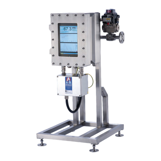
USER HANDBOOK:
OIW - EX SERIES SIDE STREAM
OIL IN WATER ANALYZERS
DOCUMENT
0IW - HBO - 0002
VERSION: EX-005
CODE:
World's Best
Oil in Water
Analyzers
Table of
Contents
Previous
Page
Next
Page
1
2
3
4
5
Advertisement
Table of Contents
Troubleshooting
SECTION 4 - SYSTEM LOGS AND TROUBLESHOOTING
62
Troubleshooting
67
Need help?
Do you have a question about the OIW-EX Series and is the answer not in the manual?
Ask a question
Questions and answers
Related Manuals for Advanced Sensors OIW-EX Series
Measuring Instruments Advanced Sensors OIW-EX 1000 Handbook
Oil in water monitors (33 pages)
Measuring Instruments Advanced Sensors EX-100 User Handbook Manual
Oil in water analyzers (94 pages)
This manual is also suitable for:
Ex-100
Ex-1000p2
Ex-1000
Ex-1000p
Ex-100p
Table of Contents
Save PDF
Print
Rename the bookmark
Delete bookmark?
Delete from my manuals?
Login
Sign In
OR
Sign in with Facebook
Sign in with Google
Upload manual
Upload from disk
Upload from URL


Need help?
Do you have a question about the OIW-EX Series and is the answer not in the manual?
Questions and answers