Table of Contents
Advertisement
Quick Links
Advertisement
Table of Contents

Related Manuals for Analog way NATIX NTX8022A


Summary of Contents for Analog way NATIX NTX8022A
- Page 1 MODELS: NTX8022A & NTX8022A-D User’s Manual ANALOG WAY® NATIX™ EDITION : 12/04...
-
Page 3: Table Of Contents
NATIX™ TABLE OF CONTENTS SAFETY INSTRUCTIONS................................4 Chapter 1 : INTRODUCTION...............................7 1-1. SUPPLIED EQUIPMENT..............................7 1-2. GENERAL INFORMATION.............................7 1-3. REFERENCES ...................................8 1-4. OPTIONAL ACCESSORIES.............................8 1-5. INSTALLATION ................................8 1-6. FRONT PANEL DESCRIPTION............................9 1-7. REAR PANEL DESCRIPTION ............................10 Chapter 2 : CONNECTING .................................11 2-1. CONNECTING THE NATIX™ ............................11 2-2. -
Page 4: Safety Instructions
NATIX™ SAFETY INSTRUCTIONS All of the safety and operating instructions should be read before the product is operated and should be retained for further reference. Please follow all of the warnings on this product and its operating instructions. CAUTION: WARNING: To prevent the risk of electric shock and fire, do not expose this device to rain, humidity or intense heat sources (such as heaters or direct sunlight). - Page 5 NATIX™ INSTRUCTIONS DE SÉCURITÉ Afin de mieux comprendre le fonctionnement de cet appareil nous vous conseillons de bien lire toutes les consignes de sécurité et de fonctionnement de l’appareil avant utilisation. Conserver les instructions de sécurité et de fonctionnement afin de pouvoir les consulter ultérieurement. Respecter toutes les consignes marquées dans la documentation, sur le produit et sur ce document.
- Page 6 NATIX™ SICHERHEITSHINWEISE Um den Betrieb dieses Geräts zu verstehen, raten wir Ihnen vor der Inbetriebnahme alle Sicherheits- und Betriebsanweisungen genau zu lesen. Diese Sicherheits- und Betriebsanweisungen für einen späteren Gebrauch sicher aufbewahren. Alle in den Unterlagen, an dem Gerät und hier angegebenen Sicherheitsanweisungen einhalten.
-
Page 7: Chapter 1 : Introduction
1-2. GENERAL INFORMATION ™ NATIX by Analog Way is an 8x2 Hi-res Scaled Native Matrix with 8 universal inputs and different resolutions on each ™ output. NATIX performs ultra smooth and fast switching transitions with no artifacts (independently on the 2 outputs). -
Page 8: References
Chapter 1 : INTRODUCTION (continued) NATIX™ 1-3. REFERENCES REFERENCES DESIGNATIONS ™ NTX8022A NATIX (without option) ™ NTX8022A-D NATIX with optional SDI & DVI inputs. OPT-iX-SDTVD1 Optional SDTV video output (COMPOSITE VIDEO + S.VIDEO + YUV + SDI). 1-4. OPTIONAL ACCESSORIES REFERENCES DESIGNATIONS ™... -
Page 9: Front Panel Description
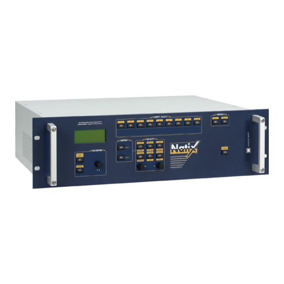
NATIX™ Chapter 1 : INTRODUCTION (continued) 1-6. FRONT PANEL DESCRIPTION Figure 2 LCD CONTROL EXIT/MENU: Switches between Status and Control mode. ENTER: Validates a selected item. Allows scrolling thru the different menus. INPUT SELECT 1 to 8: Input source selection. BLACK: Black screen selection. -
Page 10: Rear Panel Description
Chapter 1 : INTRODUCTION (continued) NATIX™ 1-7. REAR PANEL DESCRIPTION Figure 3 100-240 Vac 3A 50-60Hz: IEC standard power connector. O / I : Power switch (O = OFF, I = ON) INPUTS 1 to 8: 8 Universal Computer & Video Inputs. Each of the 8 inputs can accept both COMPUTER sources (RGBHV, RGBS, and RGsB (SOG) signals), standard TV/VIDEO sources (Composite video, S.VIDEO, Component (YUV), RGBS &... -
Page 11: Chapter 2 : Connecting
NATIX™ Chapter 2 : CONNECTING 2-1. CONNECTING THE NATIX™ Turn OFF all of your equipment before connecting. Connect your computers (PC, MAC, workstation) and your video sources to the inputs (1 to 8) of the device. Connect your display devices (data projector, plasma screen...) to the outputs 1 & 2. Connect your control monitors to the outputs 1 &... - Page 12 Chapter 2 : CONNECTING (continued) NATIX™ 2-1. CONNECTING THE NATIX™ (continued) 2-1-1. UNIVERSAL COMPUTER & VIDEO INPUTS (continued) COMPOSITE VIDEO SOURCES: The Composite Video signal, usually called COMPOSITE or VIDEO, is available on most video equipment (VCR, DVD, CAMCORDER…), but is also the lowest in picture quality. The video standard of this signal can be NTSC, PAL or SECAM.
- Page 13 NATIX™ Chapter 2 : CONNECTING (continued) 2-1. CONNECTING THE NATIX™ (continued) 2-1-1. UNIVERSAL COMPUTER & VIDEO INPUTS (continued) COMPONENT VIDEO SOURCES: ™ The Component Video signal, also called YUV (Y, R-Y, B-Y) or BETACAM is widely used in broadcasting and is available on high-quality DVD players.
- Page 14 Chapter 2 : CONNECTING (continued) NATIX™ 2-1. CONNECTING THE NATIX™ (continued) 2-1-2. OUTPUT 1 AND OUTPUT 2 The device is equipped with 2 outputs 1 on HD15 female connector, and two outputs 2 on HD15 female connector. Connect the display devices and the control monitor to the output 1 & 2. 2-1-3.
-
Page 15: Connecting A Control Device For Using The Remote Control Software
NATIX™ Chapter 2 : CONNECTING (continued) 2-2. CONNECTING A CONTROL DEVICE FOR USING THE REMOTE CONTROL SOFTWARE ™ Your NATIX is shipped with a Windows 95 or later compatible Remote Control Software (3.5" disk). This software allows you to control and make all adjustments by a simple mouse click. NOTE: Preferably use Windows NT, 2000, or XP for LAN operation. -
Page 16: Chapter 3 : Operating Mode
NATIX™ Chapter 3 : OPERATING MODE 3-1. OPERATING WITH THE REMOTE CONTROL SOFTWARE ™ Your NATIX is shipped with a WINDOWS 95 or later compatible software. This software allows you to control and make adjustments by a simple mouse click. 3-1-1. - Page 17 NATIX™ Chapter 3 : OPERATING MODE (continued) 3-1. OPERATING WITH THE REMOTE CONTROL SOFTWARE (continued) 3-1-2. COMMUNICATION SETUP (continued) • CASE OF LAN PORT: ™ Connect the control device to the NATIX with the RS-232 port as indicated in the previous page, then configure the LAN communication port (local address &...
- Page 18 Chapter 3 : OPERATING MODE (continued) NATIX™ 3-1. OPERATING WITH THE REMOTE CONTROL SOFTWARE (continued) 3-1-3. OPERATING • SETTINGS We recommend resetting the device to its default values (Controls menu > default value) before proceeding. Click on Settings then click on the Input tab and select the signal type of each source connected to the inputs. Click on the Output 1 tab and select the output sync according to your display device.
- Page 19 NATIX™ Chapter 3 : OPERATING MODE (continued) 3-1. OPERATING WITH THE REMOTE CONTROL SOFTWARE (continued) 3-1-3. OPERATING (continued) • DISPLAY DEVICES ADJUSTMENTS For each OUTPUT: Click on the Output tab and select the centering pattern. Adjust directly the display device itself, using its controls, to fill the centering pattern in full screen. Figure 17: Centering pattern.
-
Page 20: Operating With The Front Panel Of The Natix
Chapter 3 : OPERATING MODE (continued) NATIX™ 3-2. OPERATING WITH THE FRONT PANEL OF THE NATIX™ 3-2-1. OPERATING MODE • SETTINGS ™ We recommend resetting the NATIX device to its default values, with the LCD menu (CONTROL > default value > yes) before proceeding. Select the input type connected to the inputs with the LCD menu (INPUT >... - Page 21 NATIX™ Chapter 3 : OPERATING MODE (continued) 3-2. OPERATING WITH THE FRONT PANEL OF THE NATIX™ (continued) 3-2-1. OPERATING MODE (continued) • DISPLAY DEVICES ADJUSTMENTS For each OUTPUT: Select the centering pattern with the LCD menu (OUTPUT X > test pattern > centering pattern). Adjust directly the display device itself, using its controls, to fill the centering pattern in full screen.
-
Page 22: Operating With The Remote Keypad
Chapter 3 : OPERATING MODE (continued) NATIX™ 3-3. OPERATING WITH THE REMOTE KEYPAD 3-3-1. COMMUNICATION SETUP • CASE OF RS-232 PORT ™ Connect the REMOTE KEYPAD to the NATIX according to your installation (see section 2-3-1. ) Then only power ON all the devices. Activate the REMOTE KEYPAD RS232 communication port with the LCD of the REMOTE KEYPAD (CONSOLE >... - Page 23 NATIX™ Chapter 3 : OPERATING MODE (continued) 3-3. OPERATING WITH THE REMOTE KEYPAD (continued) 3-3-2. OPERATING IN MATRIX MODE • SETTINGS ™ We recommend resetting the NATIX device to its default values, with the LCD menu (CONTROL > default value > yes) before proceeding. ™...
- Page 24 Chapter 3 : OPERATING MODE (continued) NATIX™ 3-3. OPERATING WITH THE REMOTE KEYPAD (continued) 3-3-2. OPERATING IN MATRIX MODE (continued) • IMAGE ADJUSTMENTS ™ For each input source connected to the NATIX make the following adjustments: Select the source you want to adjust. Select the aspect ratio of your input source with the LCD menu (IMAGE >...
-
Page 25: Chapter 4 : Updating
Switch OFF the device (rear panel switch = O). Figure 20: Updating. 4-2. UPDATE INSTRUCTIONS Open the file "iX updater" (in start/Program/ANALOG WAY/iX8022). Click on "START" on the SOFTWARE. Switch ON the device. The POWER LED blinking slowly and the update will start. -
Page 26: Chapter 5 : Using Frame Store And Logo Insertion
NATIX™ Chapter 5 : USING FRAME STORE AND LOGO INSERTION 5-1. USING LOGO INSERTION WITH THE REMOTE CONTROL SOFTWARE This function allows storing up to 8 logos in order to incrust them into the displayed image (up to 2 logos at a same time). IMPORTANT: The output format used when displaying logo should be the same that the output format used during the logo storing. -
Page 27: Using Frame Store With The Remote Control Software
NATIX™ Chapter 5 : USING FRAME STORE AND LOGO INSERTION (continued) 5-1. USING LOGO INSERTION WITH THE REMOTE CONTROL SOFTWARE (continued) 5-1-5. EXAMPLE OF LOGO INSERTION Figure 22 Logo source Video source Video source with inserted logo. (white border = logo area) (logo made with luma key) 5-2. -
Page 28: Using Logo Insertion With The Remote Keypad Or Natix
Chapter 5 : USING FRAME STORE AND LOGO INSERTION (continued) NATIX™ 5-3. USING LOGO INSERTION WITH THE REMOTE KEYPAD OR NATIX™ This function allows storing up to 8 logos in order to incrust them into the displayed image (up to 2 logos at a same time). IMPORTANT: The output format used when displaying logo should be the same that the output format used during the logo storing. -
Page 29: Using Frame Store With The Remote Keypad Or The Natix
NATIX™ Chapter 5 : USING FRAME STORE AND LOGO INSERTION (continued) 5-4. USING FRAME STORE WITH THE REMOTE KEYPAD OR THE NATIX™ This function allows memorizing up to 2 frames (images) in order to display it at any time during the show. IMPORTANT: The output format used when displaying the frame should be the same that the output format used during the frame storing. -
Page 30: Chapter 6 : Natix ™ & Remote Keypad Lcd Screen Description
NATIX™ ™ Chapter 6 : NATIX & REMOTE KEYPAD LCD SCREEN DESCRIPTION 6-1. INTRODUCTION The LCD screen is composed of 2 modes: the STATUS MODE and the CONTROL MODE. • The STATUS MODE indicates the input and the output status. •... -
Page 31: Control Mode
NATIX™ Chapter 6 : NATIX™ & REMOTE KEYPAD LCD SCREEN DESCRIPTION (continued) 6-4. CONTROL MODE 1 INPUT 1 input type 1 #1 Comp. HV/C 1 SDTV Composite 1 NTSC/PAL/SECAM 2 #2 Comp. HV/C 2 SDTV S.VIDEO 2 NTSC 3 #3 Comp. HV/C 3 SDTV YUV 3 PAL 4 #4 Comp. - Page 32 Chapter 6 : NATIX™ & REMOTE KEYPAD LCD SCREEN DESCRIPTION (continued) NATIX™ 6-4. CONTROL MODE (continued) 6 AUDIO OUT1 1 master volume 2 audio mode 1 mono 7 AUDIO OUT2 2 stereo 3 audio source 1 auto follow 2 input # 1 …..
-
Page 33: Lcd Functions Description
NATIX™ Chapter 6 : NATIX™ & REMOTE KEYPAD LCD SCREEN DESCRIPTION (continued) 6-5. LCD FUNCTIONS DESCRIPTION 1 [INPUT] + ENTER. 1-1 [input type] + ENTER. Select an input with + ENTER. + ENTER between: Select the input signal type with •... - Page 34 Chapter 6 : NATIX™ & REMOTE KEYPAD LCD SCREEN DESCRIPTION (continued) NATIX™ 6-5. LCD FUNCTIONS DESCRIPTION (continued) 2-3 [output sync] + ENTER. Select an output between OUT 1 & OUT 2 with + ENTER. Select the Output Sync. type with + ENTER.
- Page 35 NATIX™ Chapter 6 : NATIX™ & REMOTE KEYPAD LCD SCREEN DESCRIPTION (continued) 6-5. LCD FUNCTIONS DESCRIPTION (continued) 4 [IMAGE] + ENTER. Select an output between OUTPUT 1 & OUTPUT 2 with + ENTER. NOTE: The image menu contents will be different in case of computer or video on the input selected. 4-1 [centering] + ENTER.
- Page 36 Chapter 6 : NATIX™ & REMOTE KEYPAD LCD SCREEN DESCRIPTION (continued) NATIX™ 6-5. LCD FUNCTIONS DESCRIPTION (continued) [LOGOS/FRAME] + ENTER 5-1 [use logo/frame] + ENTER. Select an item with + ENTER. 5-1-1 [display] + ENTER. This function allows to display ON or OFF the assigned logos of the displayed input. Select the OUT 1 or the OUT 2 displayed input with and press ENTER to display ON or OFF.
- Page 37 NATIX™ Chapter 6 : NATIX™ & REMOTE KEYPAD LCD SCREEN DESCRIPTION (continued) 6-5. LCD FUNCTIONS DESCRIPTION (continued) 5-3 [record frame] + ENTER. This mode allows storing up to 2 frames in order to display them at any time during the show. 5-3-1 [H position] + ENTER.
- Page 38 Chapter 6 : NATIX™ & REMOTE KEYPAD LCD SCREEN DESCRIPTION (continued) NATIX™ 6-5. LCD FUNCTIONS DESCRIPTION (continued) 6 [AUDIO OUT 1] + ENTER. The following commands allow controlling the AUDIO output 1. 6-1 [master volume] + ENTER. + ENTER. Adjust the audio output level with 6-2 [audio mode] + ENTER.
- Page 39 NATIX™ Chapter 6 : NATIX™ & REMOTE KEYPAD LCD SCREEN DESCRIPTION (continued) 6-5. LCD FUNCTIONS DESCRIPTION (continued) 8 [CONTROL] 8-1 [versions] + ENTER. Display the status of the internal firmware. • A = xxxx • B = xxxx • X = xxxx •...
- Page 40 Chapter 6 : NATIX™ & REMOTE KEYPAD LCD SCREEN DESCRIPTION (continued) NATIX™ 6-5. LCD FUNCTIONS DESCRIPTION (continued) 8-7 [tally] + ENTER. First select a tally output with + ENTER. Then select an input for this tally output with + ENTER. 8-8 [key brightness] + ENTER.
- Page 41 NATIX™ Chapter 6 : NATIX™ & REMOTE KEYPAD LCD SCREEN DESCRIPTION (continued) 6-5. LCD FUNCTIONS DESCRIPTION (continued) 9 [CONSOLE] 9-1 [RS232/LAN port] + ENTER. Select the needed communication port with + ENTER. • [RS232] = Enables the RS-232 communication port. (Default setting). •...
-
Page 42: Chapter 7 : Remote Control Programmer's Guide
NATIX™ Chapter 7 : REMOTE CONTROL PROGRAMMER'S GUIDE 7-1. INTRODUCTION If you need to use your own Control Software from a PC, or WORKSTATION with an RS-232 port, the device allows communicating through an ASCII code protocol. The device treats any character received on its RS-232 as a possible command but, it only accepts legal commands. There is no starting/ending in a command string. -
Page 43: Commands And Responses Table
NATIX™ Chapter 7 : REMOTE CONTROL PROGRAMMER'S GUIDE (continued) 7-4. COMMANDS AND RESPONSES TABLE The following table resumes all of the commands that are recognized as valid and the responses that will be returned to the control device. ASCII COMMAND VALUE RESPONSE TYPE... - Page 44 Chapter 7 : REMOTE CONTROL PROGRAMMER'S GUIDE (continued) NATIX™ 7-4. COMMANDS AND RESPONSES TABLE (continued) ASCII COMMAND VALUE RESPONSE TYPE COMMAND DESCRIPTION MIN MAX DESCRIPTION IMAGE COMMANDS ACAD Rd/Wr 1 = centering action (automatic reset). Automatic centering (M). Horizontal position (M). Rd/Wr Vertical position (M).
- Page 45 NATIX™ Chapter 7 : REMOTE CONTROL PROGRAMMER'S GUIDE (continued) 7-4. COMMANDS AND RESPONSES TABLE (continued) ASCII RESPONSE COMMAND TYPE VALUE COMMAND DESCRIPTION MIN MAX DESCRIPTION STATUS COMMANDS UNIT Measures unity in tens of kHz. 65535 ex: 14500 = 145 MHz Horizontal period of input signal (M) 65535 Line frequency (in kHz) = (UNIT VALUE)x10 ÷...
- Page 46 Chapter 7 : REMOTE CONTROL PROGRAMMER'S GUIDE (continued) NATIX™ 7-4. COMMANDS AND RESPONSES TABLE (continued) ASCII RESPONSE COMMAND TYPE VALUE COMMAND DESCRIPTION MIN MAX DESCRIPTION CONTROLS COMMANDS TALA Input number for TALLY1 Rd/Wr 0 = input #1..TALB Input number for TALLY2. Rd/Wr 7 = input #8.
- Page 47 NATIX™ Chapter 7 : REMOTE CONTROL PROGRAMMER'S GUIDE (continued) 7-4. COMMANDS AND RESPONSES TABLE (continued) VALUE ASCII COMMAND RESPONSE TYPE COMMAND DESCRIPTION MIN MAX DESCRIPTION FRAME & LOGOS COMMANDS 0 = use & assignment mode. 1 = logo recording mode. LMOD Frame/logo mode.
- Page 48 Chapter 7 : REMOTE CONTROL PROGRAMMER'S GUIDE (continued) NATIX™ 7-4. COMMANDS AND RESPONSES TABLE (continued) VALUE ASCII COMMAND RESPONSE TYPE COMMAND DESCRIPTION MIN MAX DESCRIPTION FRAME & LOGOS COMMANDS (continued) 0 = use & assignment mode. 1 = logo recording mode. lmod Frame/logo mode.
- Page 49 NATIX™ Chapter 7 : REMOTE CONTROL PROGRAMMER'S GUIDE (continued) 7-4. COMMANDS AND RESPONSES TABLE (continued) VALUE ASCII COMMAND RESPONSE TYPE COMMAND DESCRIPTION MIN MAX DESCRIPTION COMMUNICATION PORT COMMANDS LANE Communication port selection Rd/Wr 0 = RS232 1 = LAN LANR Reset of the LAN parameters.
-
Page 50: Ascii / Hex / Dec Table
Chapter 7 : REMOTE CONTROL PROGRAMMER'S GUIDE (continued) NATIX™ 7-4. COMMANDS AND RESPONSES TABLE (continued) VALUE ASCII COMMAND RESPONSE TYPE COMMAND DESCRIPTION MIN MAX DESCRIPTION OPTIONAL AUDIO COMMANDS Audio source selection of the OUT 1. Rd/W 1 = audio source #1..8 = audio source #8. Audio source selection of the OUT 2. -
Page 51: Chapter 8 : Technical Specifications
NATIX™ Chapter 8 : TECHNICAL SPECIFICATIONS 8-1. COMPUTER & VIDEO INPUTS • COMPUTER (on HD15 or BNC female connectors). Line frequency: Up to 110 kHz. Frame frequency: Up to 130 Hz. Resolution: Up to 1600 x 1280. Sync. types: RGBHV, RGB/S, RGsB (Sync On Green). Levels: R, G, B = 0.7 Vp/p. -
Page 52: Display Outputs
Chapter 8 : TECHNICAL SPECIFICATIONS (continued) NATIX™ 8-1. COMPUTER & VIDEO INPUTS (continued) • HD15 PIN ASSIGNMENT SIGNAL COMPUTER COMPONENT COMPOSITE (RGBHV,RGB/S, RGB/S VIDEO S.VIDEO (Y/C) (YUV) VIDEO PIN # RGsB) PIN 1 RED. RED. U or Pr (R-Y). C (chrominance). PIN 2 GREEN. -
Page 53: Optional Video Outputs (Opt-Ix-Sdtvd1)
NATIX™ Chapter 8 : TECHNICAL SPECIFICATIONS (continued) 8-4. OPTIONAL VIDEO OUTPUTS (OPT-iX-SDTVD1) • COMPOSITE VIDEO (on DB9 connector) PAL / SECAM 15.625 kHz / 50 Hz (625L) NTSC 3.58 MHz / 4.43 MHz 15.735 kHz / 60 Hz (525L) Level: 1 Vp/p (0.7 V Luma + 0.3 V Sync.). -
Page 54: Audio Inputs
Chapter 8 : TECHNICAL SPECIFICATIONS (continued) NATIX™ 8-6. AUDIO INPUTS • 9 Balanced and unbalanced stereo inputs (on 5-pin MCO male connector). • Vi = + 18 dBu (max). • Zi = 20 kΩ unbalanced. • Zi = 40 kΩ balanced. •... -
Page 55: Warranty
NATIX™ WARRANTY Analog Way warrants the product against any defects in materials and workmanship for a period of three years from the date of purchase (back to the factory). In the event of any malfunction during the warranty period, Analog Way will, at its discretion, repair or replace the defective units, including free materials and labor.
Need help?
Do you have a question about the NATIX NTX8022A and is the answer not in the manual?
Questions and answers