
Related Manuals for Analog way ASC4806-4K-PL


Summary of Contents for Analog way ASC4806-4K-PL
- Page 1 USER MANUAL LiveCore™ unit (V04.02.20) References: ASC4806-4K-PL, ASC3204-4K-PL, ASC1602-4K, SMX12x4, NXT1604-4K, NXT0802-4K, LOE048-4K-PL, LOE032-4K, LOE016-4K...
- Page 3 THANK YOU By following these simple steps you will be able to obtain the most from your powerful LiveCore™ unit and its many features related to the version 04.02.20. 1. TRADEMARKS 2. INTRODUCTION 3. TERMS AND DEFINITIONS 4. HARDWARE SPECIFICATIONS 4.1 Safety instructions 4.1.1 English 4.1.2 French...
- Page 4 4.10.3 Keys’ checking 4.10.4 Output management 4.10.5 HDCP Classification 4.10.6 Status 5. CONNECTING A LIVECORE™ UNIT 5.1 Description 5.1.1 Rear panel of 4RU LiveCore™ unit 5.1.2 Rear panel of 4RU LiveCore™ unit - 4K option 5.1.3 Rear panel of 3RU LiveCore™ unit - 4K option 5.1.4 Rear panel of a LiveCore™...
-
Page 5: Table Of Contents
7.4 Edit 7.4.1 Layer management 7.4.2 Layer properties 7.4.3 Layer settings 7.4.4 Layer selection and native background 7.4.5 Preset load and save management 7.4.6 Logos and Frames management 7.4.7 Inputs management 7.4.8 Monitoring management 7.4.9 Confidence management 7.5 Live 7.6 How to operate Perspective Layers on the Ascender 48 - 4K - PL 7.6.1 Edit page 7.6.2 Memories and AUTOSCALE with Perspective Layers 8. - Page 6 HDMI Licensing LLC in the United States and other countries. 2. INTRODUCTION Thank you for choosing an Analog Way LiveCore™ unit. Before you start setting up your LiveCore™ unit for the first time, please read through all of the documentation to become familiar with its powerful features.
-
Page 7: Terms And Definitions
3. Terms and definitions 3. TERMS AND DEFINITIONS BACKGROUND: a “Background” is a source, typically originating from a computer. A LiveCore™ unit enables you to work with live or still (Frame) background sources — visually in back of all other sources. LAYER: a “Layer”... - Page 8 4.1 Safety instructions 4. HARDWARE SPECIFICATIONS 4.1 Safety instructions 4.1.1 English All of the safety and operating instructions should be read before the product is operated and should be maintained for further reference. Please follow all of the warnings on this product and its operating instructions.
- Page 9 4.1 Safety instructions 4.1.2 French Afin de mieux comprendre le fonctionnement de cet appareil nous vous conseillons de bien lire toutes les consignes de sécurité et de fonctionnement avant utilisation. Conservez les instructions de sécurité et de fonctionnement afin de pouvoir les consulter ultérieurement. Respectez toutes les consignes marquées dans la documentation, sur le produit et sur ce document.
- Page 10 4.1 Safety instructions 4.1.3 Italian Allo scopo di capire meglio il funzionamento di questa apparecchiatura vi consigliamo di leggere bene tutti i consigli di sicurezza e di funzionamento prima dell’utilizzo. Conservare le istruzioni di sicurezza e di funzionamento al fine di poterle consultare ulteriormente. Seguire tutti i consigli indicati su questo manuale e sull’apparecchiatura.
- Page 11 4.1 Safety instructions 4.1.4 German Um den Betrieb dieses Geräts zu verstehen, raten wir Ihnen vor der Inbetriebnahme alle Sicherheits und Betriebsanweisungen genau zu lesen. Diese Sicherheits- und Betriebsanweisungen für einen späteren Gebrauch sicher aufbewahren. Alle in den Unterlagen, an dem Gerät und hier angegebenen Sicherheitsanweisungen einhalten.
- Page 12 4.1 Safety instructions 4.1.5 Spanish Para comprender mejor el funcionamiento de este aparato, le recomendamos que le acuidadosamente todas las consignas de seguridad y de funcionamiento del aparato antes de usarlo. Conserve las instrucciones de seguridad y de funcionamiento para que pueda consultarlas posteriormente. Respete todas las consignas indicadas en la documentación, relacionadas con el producto y este documento.
-
Page 13: Unpacking And Inspection
Before racking and plugging any inputs and outputs, it is advised to power on the unit. Should you encounter any issue, you must contact immediately your local distributor or dealer, or closest Analog Way technical (see chapter: 14. Contact support offices information). - Page 14 4.4 Cable and adaptor information Dismantling front handles of the device could invalidate warranty on after-sales services of your LiveCore™ unit. It is strongly advised to avoid using front handles as rests for your LiveCore™ unit, they are designed for manipulation purposes only. If required, front handles of the device can be dismantled, but with caution.
-
Page 15: Signal Descriptions
4.5.1 Signal descriptions Analog HDTV Digital HDTV These formats are compatible with bi-level and tri- Type Characteristics level sync on 1 or 3 wires. HD-SDI YUV - 10 bits – 4.2.2 – 1,485Gb/s and 1,485/1.001Gb/s Type Levels Impedance Only A-level type Y = 0,7 Vpp ±0,3 Vpp Input and output payload ID management U = 0,7 Vpp ±0,3 Vpp... - Page 16 4.5.2 Supported video formats 4.5.2 Supported video formats A LiveCore™ unit can support all the following video formats: SDTV formats Standard Size Vertical frequency Horizontal frequency NTSC 525/480i 59.94Hz/60Hz 15,735 KHz 625/576i 50Hz 15.625 KHz SECAM 625/576i 50Hz 15.625 KHz EDTV formats Standard Size...
- Page 17 4.5.5 Output Computer formats 4.5.5 Output Computer formats The outputs of a LiveCore™ unit support GTF (version 1.1), CVT (version 1.1) and DMT (version 1.0 rev 12) standards. Other non-standard formats are supported via the Custom Format capability. A LiveCore™ unit offers a list of pre-defined output formats. The list of output formats is always displayed from increasing number of pixels per line and then number of lines.
- Page 18 4.6 Input specifications For devices with the 4K input card: A LiveCore™ unit uses an HDMI plug with a standard mounting screw above the connector. Please see the diagram below. This hole is occupied by a Torx10 screw when you receive the unit.
- Page 19 4.6 Input specifications 4-Lanes Dis- Single-Link Dual-Link Standard Size HD-15 3G-SDI HDMI HDMI 4K playPort DVI-I DVI-D NTSC 525/480i 625/576i SECAM 625/576i 480p 525/480p 576p 625/576p 720p 1280x720 1035i 1920x1035 1080i 1920x1080 1080p 1920x1080 1080sF 1920x1080 1080p 1920x1080 DCDM 2048x1080 640x480 800x480 800x480...
-
Page 20: Output Specifications
4.7.1 Standard output 4.7 Output specifications 4.7.1 Standard output A LiveCore™ unit has two standard output modules. The standard module contains two outputs with the following plugs: - 3G/HD/SD-SDI (two clone outputs via 1 BNC and 1 dual video optical SFP module), - Analog Computer/Video (HD15), - DVI: Dual-Link DVI-I for output #1 and Single-Link DVI-I on output #2 (both with DVI-I connectors). -
Page 21: Communication Specifications
4.8 Communication specifications 4.8 Communication specifications 4.8.1 Serial interface A RS-232 compliant link is available through a DB-9 Link Baud rate connector. This serial interface is reserved for factory RS-232 Link Will depend on debug application purpose and communication with the SPU001 external power mode. - Page 22 4.8.6 Compliance 4.8.6 Compliance This interface is fully compliant with USB 2.0 High Speed specification (up to 480 Mbps). Pin number Function Ground SUPPORTED CLASSES Class Availability SCSI Mass Storage...
-
Page 23: Environmental Specifications
4.9.1 Ascender 48 - 4K - PL 4.9 Environmental specifications 4.9.1 Ascender 48 - 4K - PL Dimensions: Weight: W 482 x D 552 x H 177 mm with rack mount and handles 19,4 kg / 42.77 lbs ... - Page 24 4.9.2 Ascender 32 - 4K - PL 4.9.2 Ascender 32 - 4K - PL Dimensions: Weight: W 482 x D 552 x H 177 mm with rack mount and handles 19 kg / 41.89 lbs 19”W x 23.73”D x 6.97”H (Compatible with a Standard 19”...
- Page 25 4.9.3 Ascender 16 - 4K 4.9.3 Ascender 16 - 4K Dimensions: Weight: W 482 x D 544 x H 177 mm with rack mount and handles 19 kg / 41.89 lbs 19”W x 23.73”D x 6.97”H (Compatible with a Standard 19”...
- Page 26 4.9.4 SmartMatriX Ultra 4.9.4 SmartMatriX Ultra Dimensions: Weight: W 482 x D 544 x H 177 mm with rack mount and handles 19 kg / 41.89 lbs 19”W x 23.73”D x 6.97”H (Compatible with a Standard 19” rack, Height = 4 U) ...
- Page 27 4.9.5 NeXtage 16 - 4K 4.9.5 NeXtage 16 - 4K Dimensions: Weight: W 482 x D 544 x H 133 mm with rack mount and handles 15,1 kg / 33.29 lbs 19”W x 21.41”D x 6.97”H (Compatible with a Standard 19”...
- Page 28 4.9.6 NeXtage 08 - 4K 4.9.6 NeXtage 08 - 4K Dimensions: Weight: W 482 x D 544 x H 133 mm with rack mount and handles 14,8 kg / 32.63 lbs 19”W x 21.41”D x 6.97”H (Compatible with a Standard 19”...
- Page 29 4.9.7 LiveCore™ Output Expander 4.9.7 LiveCore™ Output Expander - Ref. LOE048-4K-PL, LOE032-4K-PL, LOE016-4K Dimensions: Weight: W 482 x D 552 x H 177 mm with rack mount and handles 18,4 kg / 40.56 lbs 19”W x 23.73”D x 6.97”H (Compatible with a Standard 19”...
- Page 30 4.10 HDCP management 4.10 HDCP management 4.10.1 Input HDCP detection The input HDCP detection is managed by the input components according to HDCP specification. 4.10.2 Output HDCP detection LiveCore™ unit manages the output HDCP detection according to one of the following criteria: - Hot plug, - 3-second period attempt.
- Page 31 5.1.1 Rear panel of 4U LiveCore™ unit 5. CONNECTING A LIVECORE™ UNIT 5.1.1 Rear panel of 4RU LiveCore™ unit 10 9 1. Power supply: internal, autoswitching ; Typical consumption: Ascender 48 - 4K - PL: 405W / Ascender 32 - 4K - PL: 345W / Ascender 16 - 4K: 285W / SmartMatriX Ultra: 285W ; 2.
- Page 32 5.1.2 Rear panel of 4RU LiveCore™ unit - 4K option 5.1.2 Rear panel of 4RU LiveCore™ unit - 4K option 10 9 1. Power supply: internal, autoswitching ; Typical consumption: Ascender 48 - 4K - PL: 405W / Ascender 32 - 4K - PL: 345W / Ascender 16 - 4K: 285W / SmartMatriX Ultra: 285W ;...
- Page 33 5.1.3 Rear panel of 3RU LiveCore - 4K 5.1.3 Rear panel of 3RU LiveCore - 4K 10 9 1. Removable Power supply: 100-240 VAC 8A 50/60Hz, 240W 2. Inputs #1 to #8: - 4 x HDMI (4K available on inputs #2 and #6) - 6 x DVI-I (Dual link available on Inputs #2 and #6) - 2 x DisplayPort (Dual link available on Inputs #4 and #8) - 8 x 3G/HD/SD-SDI...
- Page 34 5.1.4 Rear panel of a LiveCore™ Output Expander 5.1.4 Rear panel of a LiveCore™ Output Expander 1. Power supply: internal, autoswitching ; Typical consumption: 405W 2. Outputs #5, #6, #7 & #8: - 8 x Universal Analog (4 x HD15 & 4 x DVI-A) - 4 x DVI-I (DVI Dual-Link on outputs #5 &...
- Page 35 5.1.5 Front panel of Ascender 48 - 4K - PL 5.1.5 Front panel of Ascender 48 - 4K - PL 1. On/Off - Stand-by: Push the button then use the contextual button to enter in stand-by mode 4,3’’ TFT color display (with WVGA resolution) Contextual buttons Menu scroll knob 5.
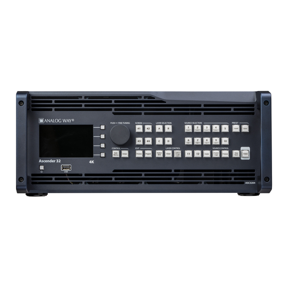
- Page 36 5.1.6 Front panel of Ascender 32 - 4K - PL 5.1.6 Front panel of Ascender 32 - 4K - PL 1. On/Off - Stand-by: Push the button then use the contextual button to enter in stand-by mode 4,3’’ TFT color display (with WVGA resolution) Contextual buttons Menu scroll knob 5.
- Page 37 5.1.7 Front panel of Ascender 16 - 4K 5.1.7 Front panel of Ascender 16 - 4K 1. On/Off - Stand-by: Push the button then use the contextual button to enter in stand-by mode 4,3’’ TFT color display (with WVGA resolution) Contextual buttons Menu scroll knob 5.
- Page 38 5.1.8 Front panel of SmartMatriX Ultra 5.1.8 Front panel of SmartMatriX Ultra 1. On/Off - Stand-by: Push the button then use the contextual button to enter in stand-by mode 4,3’’ TFT color display (with WVGA resolution) Contextual buttons Menu scroll knob 5.
- Page 39 5.1.9 Front panel of NeXtage 16 - 4K 5.1.9 Front panel of NeXtage 16 - 4K 1. On/Off - Stand-by: Push the button then use the contextual button to enter in stand-by mode 4,3’’ TFT color display (with WVGA resolution) Contextual buttons Menu scroll knob 5.
- Page 40 5.1.10 Front panel of NeXtage 08 - 4K 5.1.10 Front panel of NeXtage 08 - 4K 1. On/Off - Stand-by: Push the button then use the contextual button to enter in stand-by mode 4,3’’ TFT color display (with WVGA resolution) Contextual buttons Menu scroll knob 5.
- Page 41 5.1.11 Front panel of a LiveCore™ Output Expander 5.1.11 Front panel of a LiveCore™ Output Expander 1. On/Off - Stand-by: Push the button then use the contextual button to enter in stand-by mode 4,3’’ TFT color display (with WVGA resolution) Contextual buttons Menu scroll knob 5.
- Page 42 6.1 Web-based RCS requirement 6. CONTROLLING A LIVECORE™ UNIT 6.1 Web-based RCS requirement A LiveCore™ unit can be controlled and operated either via the Front Panel, from your computer via the Web RCS, or via one or our Event Controllers. (Control of the LiveCore™ unit can also be integrated into automation and control systems, contact your local technical support for more details.) The recommended requirements are: Operating system:...
- Page 43 6.3 Web RCS top Menu Once connected this screen will appear: In case of difficulties: - Verify that you are using the correct network cable and that it is free from defects. (Crossover or straight cable as required.) - Check the IP address of your control computer. It must have a unique IP address on the same network as your LiveCore™...
- Page 44 7.1 Functional mode 7. OPERATING A LIVECORE™ UNIT FROM THE WEB RCS 7.1 Functional mode Unlike some other devices, LiveCore™ unit is not defined by an overall operating mode. Each output is configured individually. LiveCore™ unit can be used in Mixer mode, Soft Edge Blending mode, as well as a Hybrid mode.
- Page 45 7.2 Display configurations Monitoring output The monitoring output is a configurable multiviewer output that can display a user customizable selection of program, preview, source, and frame inputs as display resources. See the following examples: MULTI-SCREEN CONFIGURATION Monitoring output* 11 12 In10 In11 In12...
- Page 46 7.3 Setup 7.3 Setup Note that all the screenshot are made with an Ascender 48 - 4K - PL. Some features including number of layers, number of outputs, and number of inputs can change depending on the LiveCore™ model. Go to the Setup section to start setting up your unit.
- Page 47 7.3.2 Link section Once the source is defined, a summary of your rate settings is displayed under the tab STATUS. WARNING: Configuring the rate to follow a framelock input will lock the output frame rate to match the selected source. This is useful to eliminate the “strobing effect” which may be visible as an artifact of the framelocking process.
- Page 48 7.3.3 Outputs section To activate an output for 4K resolutions via HDMI 1.4 (on units with the 4K hardware option), drag the adjacent resources to outputs #2 or #4 and then check the Dual-Link/4K option box. For the 4K/420 option, drag 4 output resources to output #2.
- Page 49 7.3.4 Screens 7.3.4 Screens The screens page allows you to map a particular output to a particular screen destination or part of a screen. You can map any output to any screen. To map an output to a particular screen, simply drag and drop the output to the desired screen destination.
- Page 50 (see 7.3.3 Outputs section for more information). Please note that on the Ascender 48 - 4K - PL (Ref. ASC4806-4K-PL) and the Ascender 32 - 4K - PL (Ref. ASC3204-4K-PL) , the Perspective Layers option must be enabled here. Please refer to the chapter 7.6 How to operate Perspective Layers on the Ascender 48 - 4K - PL &...
- Page 51 7.3.4 Screens Examples of custom canvas screen configurations: 1 screen: 2 outputs with different formats as Hard Edge 1 screen: 4 outputs with different formats and rotations 1 screen: 2 outputs with different formats on a commonly displayed area...
- Page 52 7.3.5 Inputs section - LOAD FROM TEMPLATES: The Load From Template button (located in the upper right side corner) will help you build your grid screen configurations based on predefined templates. Available templates include: 4 independent screens, blends of 2 projectors, blends of 4 projectors, setup for 4K via quad output, and more.
- Page 53 7.3.7 Native background section 7.3.7 Native background section The native background is an additional layer which is under all the other layers. An input source, a frame or a color can be assigned to the native background. The specification of the native background is that an input source or a Frame loaded into that layer will not be scaled (1:1).
- Page 54 7.3.8 The Miscellaneous section 7.3.8 The Miscellaneous section - DYNAMIC FIT: Enable or disable the automatic layer size adaptation depending the source aspect. If disabled with a larger layer, space around the source is filled in black. - PREVIEW ASPECT: Change between 3 ways of displaying the Preview during transition.
- Page 55 7.3.9 Output management Once the output setup page is loaded, you can edit the following output settings: - RATE: Choose the rate for the output (4 outputs units only). Note: the Internal Rate mode allows you to synchronize the output to the system clock, and it is required on all soft-edge/hard-edge outputs. The latency of outputs not using the internal rate mode will be increased by one frame due to the frame rate conversion.
- Page 56 7.3.9 Output management - FLICKER: Choose the value of the flicker filter to remove the flicker effect on your interlaced output screen. - GAMMA: Increase or decrease the gamma of your output. - BRIGHTNESS: Adjust the brightness level. - CONTRAST: Adjust the contrast level.
- Page 57 7.3.9 Output management - In CVT mode, you only need to set the width, height and rate of the format and indicate if the format has reduced blanking intervals. The system computes the remaining format parameters according to the CVT 1.1 standard. - In FULL mode, you can set all the parameters of the format (H&V front porch, H&V sync, H&V back porch, width, height, sync polarity, ...).
- Page 58 7.3.10 Input management 7.3.10 Input management Once your outputs are configured, you have now to configure the inputs connected to your LiveCore™ unit. Under the Inputs section, you can view your inputs by active plugs or by all plugs (active and inactive). All plugs view for 4K devices In both cases, an AUTOSET ALL can be launched to set up automatically your inputs.
- Page 59 7.3.10 Input management Under the SIGNAL tab, you will find: - ACTIVE PLUG: Select the plug used by the unit at the moment. Only this plug can be displayed on your output. - SETUP PLUG: Select the plug you want to set up, all changes will be applied to this plug, even if this plug is active or not.
- Page 60 7.3.10 Input management 4K (change only into the setup assistant > INPUTS, only for 4K devices) The HDMI 4K inputs can be supported on the LiveCore™ unit for devices with the optional 4K. In order to use a 4K resolution, select the input #2, #6 and #10 and select 4K. When the 4K feature is activated for an input, it automatically disables the adjacent input: input #1 linked to input #2, input #5 linked to input #6 and input #9 linked to input #10.
- Page 61 7.3.10 Input management Under the OPTIMIZE section – only for analog signals, you have: - AUTO CENTER: Automatic search of the right Clock and Phase of your input analog computer signal. In other words, it automatically searches for the first and the last pixel of the signal. There are two modes: a quick search and an advanced search typically launched when the source is rich in content such as a vertical burst.
- Page 62 7.3.10 Input management Under the ASPECT RATIO section: ASPECT IN: Selects the correct aspect ratio of your input (5:4 4:3 etc…). This setting doesn’t exist when the input is set as native. - PREDEFINED CROP: Chooses a specific cropped ratio if you use a source with black bands on top/bottom or left/right - ASPECT OUT: Defines the way the image is displayed into a layer (full screen, centered, cropped or 1:1)
- Page 63 - CREMATTE® : The new algorithm of color keying developed by Analog Way. This keying will per- form advanced effects on transparent items, smooth edge and color correction. Keying setup can be done either by setting directly color references and tolerances or by using the color grab assistant.
- Page 64 7.3.10 Input management KEYING ASSISTANT: To enable the keying assistant click on: Then use the white square to define an area which exemplifies the color you want to key. NOTE: You can use shift on your computer keyboard in order to size the white square. For the first application, we advise you to reset all the previous keying settings.
- Page 65 HOW TO USE THE CREMATTE® KEYING: The CremaTTe® algorithm was developed by Analog Way to perform a high quality keying. If your live source contains some transparent area or if you need to key a difficult video of people with wispy hair, you need to use CremaTTe®...
- Page 66 7.3.11 Library management 7.3.11 Library management Under the SETUP > LIBRARY tab, you have access to 100 empty library slots that you can fill with your own frame and logo images. IMAGE UPLOAD You can upload the following image formats to the library: Format Download Transparency support...
- Page 67 7.3.11 Library management 4K AND DUAL-SIZE FRAMES If the image size allows it, you may select the type of frame/ logo to create from the uploaded image: - Frame: upload as single frame (up to 2.4Mpx) - Logo: upload as logo (up to 1.2Mpx) - DUAL: upload as dual-size frame (up to 4.8Mpx) - 4K: upload as a 4K frame (up to 9.4Mpx) The system will automatically fit the uploaded image to the se-...
- Page 68 7.3.11 Library management frames and logos via this one identical library (the master library). Please note that the total number of available slots in the library remains 100, and that 4K and Dual frames will still require 4 and 2 frame resources, respectively. A notification will be displayed as long as a synchronization is required, and it will disappear as soon as the synchronization is complete.
- Page 69 7.3.12 Logo management 7.3.12 Logo management You can use frame and logo slots to preset your still images before using them with the device. There are 4 frame slots and 4 logo slots available that you can fill with stills from the library. Frame slots will accept both frame and logo stills, whereas logo slots will accept logo stills only.
- Page 70 7.3.13 Monitoring management 7.3.13 Monitoring management The Monitoring output allows you to have a full Preview of your different outputs but also your sources. In addition, you have access to a lot of status shortcuts directly on the screen like HDCP status, KEYING status, FREEZE status etc.
- Page 71 7.3.14 Blending management To setup an effective blend, you will first need to physically align the projected images so they are square with each other. Remember that you can adjust the number of lines and rows on the LiveCore™ grid test pattern. to assist you.
- Page 72 Click on “Select a file on your disk” button in order to open the directory file on your computer. Simply select the file you take from Analog Way’s servers and click ok. Then click on GO to launch the update.
- Page 73 7.3.15 Services management HARDWARE INFORMATION: Here is a summary of all the cards information, Name ID etc... This is only for maintenance purpose. In case of issue, it will provide information to the technical support. TECHNICAL SUPPORT: You will find contact for our local technical support departments located throughout the world.
- Page 74 7.3.16 Control management 7.3.16 Control management Network The web interface loaded into the unit uses the IP configuration. Under INTERFACE, you can define a new: - IP address - Netmask - Gateway - Port: Choose the port - Protocol: Choose TCP (by default) or UDP Choose DHCP if you want an automatic IP address assignment.
- Page 75 7.3.16 Control management Details can be seen clicking on the magnifying glass. Inputs EDID settings are EDIDs assigned on the inputs. There are default EDIDs, it can be modified by dropping EDIDs from the Library. Each EDID (one per input type, for each input) can be reset to factory.
- Page 76 7.3.16 Control management Each GPO can sink a current of up to 300mA maximum in the closed state and can accept up to 48V in the opened state. The courant leakage is less than 1µA when opened and the resistance is less than 2 ohms when closed.
- Page 77 7.3.16 Control management Auto Calibrate (See chapter: 11. Click on start to launch an auto calibration of colors, on your analog input/output chips. Maintenance and support) Erase memories Into this section, you can erase individual settings. • Erase input settings memory: All input settings will return to their default value.
-
Page 78: Edit
7.4.1 Layer management 7.4 Edit 7.4.1 Layer management When you enter into the Edit menu, you will encounter a display of the program and preview windows for one destination screen, as well as access to select the sources, layer properties, and presets. -
Page 79: 7.4.2 Layer Properties
7.4.2 Layer properties In this example, different inputs are as- signed to each of the 6 layers into the Screen 1 Preview. Pressing the TAKE button on the bottom right side will update the Program screen based on the configuration that’s been arranged in Preview. -
Page 80: 7.4.2 Layer Properties
KEEP ASPECT RATIO button. You will find it on the right of the width and height cursors. Please note that on the Ascender 48 - 4K - PL (Ref. ASC4806-4K-PL), the axe Z can be modified as well as the Please refer to the chapter 7.6 How to operate Perspective Layers on the Ascender 48 -... -
Page 81: 7.4.3 Layer Settings
Please note that on the Ascender 48 - 4K - PL (Ref. ASC4806-4K-PL), the depth of the PIP during the transition Please refer to the chapter 7.6 How to operate Perspective Layers on the Ascender 48 - 4K can be modified. -
Page 82: 7.4.3 Layer Settings
7.4.3 Layer settings Timing The Timing section allows for individual setting of the opening and closing effects of each layer in a particular preset. The overall preset duration timing is defined next to the Take button, it defines the total duration of the transition. -
Page 83: 7.4.4 Layer Selection And Native Background
Please Please note that on the Ascender 48 - 4K - PL (Ref. ASC4806-4K-PL), perspective layouts are available. refer to the chapter 7.6 How to operate Perspective Layers on the Ascender 48 - 4K - PL for more details. -
Page 84: 7.4.4 Layer Selection And Native Background
7.4.4 Layer selection and native background Layer position A layer position shortcut is also available. After selecting a layer, click on the Pos. button to have quickly access to a predefined layer position. Choose the new position. The change is applied straight away on your preset. -
Page 85: 7.4.4 Layer Selection And Native Background
7.4.4 Layer selection and native background * A confirmation will be asked to take into account the operation, the icon has to be clicked two times. Other layer adjustments: - CLEAR BUTTON: This button allows you to clear the selected layer from your preset - CLEAR ALL BUTTON: Clicking this button removes all layers’... -
Page 86: 7.4.4 Layer Selection And Native Background
7.4.4 Layer selection and native background The Background Cut is a feature developed by Analog Way engineers which allows you to perform an amazing effect based on crop feature. The Background Cut calculates automatically, depending on your layers sizes/positions, the specific layer crop, in order to create a full screen image. -
Page 87: 7.4.4 Layer Selection And Native Background
7.4.4 Layer selection and native background To go deeper with this effect you can try it with different preset layout: NOTE: Don’t forget to press the FILL button after changing your layout in order to calculate the new crop according to the new layer positions If you want, for any reason, to reset the background cut feature, simply reset your layer Or reset manually each layer crop by using: - SNAP TO GRID:... -
Page 88: 7.4.4 Layer Selection And Native Background
7.4.4 Layer selection and native background - MIRROR BUTTON: The mirror button allows you to define for each layer the way it will be mirrored from one Screen to another Screen. You can choose to mirror the layer, flip the position, or flip the position and the data from another screen. -
Page 89: 7.4.5 Preset Load And Save Management
7.4.5 Preset load and save management 7.4.5 Preset load and save management Save a preset Once your layers are set up, you can save your current screen configuration in one of the 144 preset memory slots available. Click on SAVE MODE at the top of the Preset Mem. -
Page 90: 7.4.6 Logos And Frames Management
7.4.6 Logos and Frames management At load, you can further apply new filters: both currently selected filters and saved filters (if any) will be See also 7.5 Live: FILTER FEATURE applied when the preset is loaded. Reset button You can reset the program or preview using the reset button. Using that, all layer attributes will be reset. -
Page 91: 7.4.8 Monitoring Management
7.4.8 Monitoring management Properties Click on the Properties left side toolbar and then on Templates > Load Template to set the monitoring layout. The Display on layout view option enables a feedback of the number of resources used to display one widget. Displaying a multi-stream source like a blended screen or dual-link input will limit the number of elements that can be displayed. -
Page 92: 7.4.9 Confidence Management
7.4.9 Confidence management Like for preset and monitoring memories, you can also use the Memories Overview box at the bottom of the Memories toolbar to review the content of your confidence memories: - Hover over a confidence memory to have an overview of the memory. - SHIFT+click on a confidence memory to label the memory. -
Page 93: Live
7.5 Live 7.5 Live Default settings of the Lve mode enables to display all the screens and enables the TAKE button to affect all Screens. On the right, you will find all your memorized presets under the tab called “ MEMORIES ”. A simple drag and drop on the screen will load your preset into the screen (Program or Preview). - Page 94 7.5 Live A FADE TO BLACK and a STEP BACK buttons are also available. The FADE TO BLACK transforms your Program in a black screen using a fade effect on all your layers. The FADE TO BLACK feature remains enabled until the FADE TO BLACK button is pressed again.
- Page 95 7.5 Live LOADING MASTER MEMORIES: The Master Memory is now saved, and can be recalled by the LOAD MASTER MEMORY button or simply by drag and drop the master memory to the screen windows. Remember that like the single-screen memories, one click on a Master Memory will load it to the location of the currently selected layer.
- Page 96 7.5 Live sible cues are grouped by function and include items like “Wait for X Second” or “TAKE” or “load preset “ or “Set Frame slot 1 source” or “Set layer ful- lscreen” etc. Use the search bar at the top to help find a specific cue action.
-
Page 97: How To Operate Perspective Layers On The Ascender 48 - 4K - Pl
7.6 How to operate Perspective Layers on the Ascender 48 - 4K - PL 7.6 How to operate Perspective Layers on the Ascender 48 - 4K - PL & Ascender 32 - 4K - PL The Perspective Layers feature enables the user to modify layers within three axes and act on the rotation of the layers. -
Page 98: 7.6.2 Memories And Autoscale With Perspective Layers
7.6.2 Memories and AUTOSCALE with Perspective Layers - Flying curve The flying curve is the customizable curve for flying PIPs. When in Perspective Layers mode, the two points of the curve still can be modified and the depth of the PIP during the flying is also customizable. The drawer assistant enables the graphic modification of axes X and Y, while the Z axe has to be set on digital controls. -
Page 99: Operating Through The Front Panel
8.1.1 Front panel update 8. OPERATING THROUGH THE FRONT PANEL 8.1 Front panel 8.1.1 Front panel update Simply download the update file on your computer from the website. Then take the file LivecoreUpdate_xx_ xx_xx.awp and copy it into the root directory of your USB key. When the unit is running and the home menu is displayed, simply plug the USB key, the update is automatically detected. -
Page 100: 8.1.2 Lcd Screen
The LCD screen is a 4,3” diagonal size and a 800x480 pixels resolution. Analog Way developed an ergonomic HMI to help customer to setup the unit with the help of the front panel. You will find same settings into the front panel menu and into the Web RCS. Please refer to the specific setting chapter menu if you need accurate explanation on a setting. -
Page 101: 8.1.3 Front Panel Buttons
8.1.3 Front panel buttons Then you can build your own preset using the LAYER SELECTION buttons: • Press native BKG button then press a source button (1-8) to affect the SET 1-8 into the selected preset (selected screen/selected Program or Preview) •... -
Page 102: Menu Tree
8.2 Menu tree 8.2 Menu tree DASHBOARD ABOUT DEVICE SUMMARY INTERNAL RATE STATUS SCREENS SCREEN STATUS (1 to 4) OUTPUTS OUTPUT STATUS (1 to 4) INPUTS INPUT STATUS (1 to 12) LOGOS FRAME STATUS (1 to 4) LOGO STATUS (1 to 4) OUTPUTS OUTPUT (1 to 4) SIGNAL... - Page 103 8.2 Menu tree INPUTS INPUT (1 to 12) LABEL (ACTIVE PLUG) SIGNAL SELECT ACTIVE PLUG DVI-D HDMI ANALOG DVI-A PLUG SETUP LABEL SIGNAL TYPE ENABLE DUAL INPUT (status) NATIVE INPUT (status) CONTROL IDENTIFIER PATTERN BLACK FREEZE STATUS IMAGE SIZE FORMAT SIZE FIELD FREQUENCY LINE FREQUENCY SYNC TYPE...
- Page 104 8.2 Menu tree STATUS IMAGE SIZE FORMAT SIZE FIELD FREQUENCY LINE FREQUENCY SYNC TYPE SCAN TYPE SLOT HDCP ENABLE STATUS HDMI LABEL SIGNAL TYPE AUTO AUTO DETECT ENABLE RGB FULL (0-255) RGB LIMITED (16-255) DUAL INPUT (status) NATIVE INPUT (status) CONTROL IDENTIFIER PATTERN...
- Page 105 8.2 Menu tree COMPUTER SEPARATE HV COMPUTER TTL COMPOSITE COMPUTER ANA COMPOSITE ENABLE DUAL INPUT (status) NATIVE INPUT (status) CONTROL IDENTIFIER PATTERN BLACK FREEZE STATUS IMAGE SIZE FORMAT SIZE FIELD FREQUENCY LINE FREQUENCY SYNC TYPE SCAN TYPE SLOT DVI-A LABEL SIGNAL TYPE SDTV COMPOSITE...
- Page 106 8.2 Menu tree SCAN TYPE SLOT IMAGE COLORIMETRY BRIGHTNESS CONTRAST COLOR OPTIMIZE CLOCK PHASE USER GAIN GREEN BLUE ASPECT ASPECT RATIO ASPECT IN NONE 16:10 15:9 21:9 PREDEFINED CROP LETTERBOX 1:78 LETTERBOX 1:85 LETTERBOX 2:35 PILLARBOX 1:33 ASPECT OUT CENTERED FULLSCREEN CROPPED CROP...
- Page 107 8.2 Menu tree LOGOS FRAME (1 to 4) SOURCE ENABLE ASPECT RATIO ASPECT IN NONE 16:10 15:9 21:9 PREDEFINE CROP LETTERBOX 1:78 LETTERBOX 1:85 LETTERBOX 2:35 PILLARBOX 1:33 ASPECT OUT CENTERED FULLSCREEN CROPPED CROP FINDER BOTTOM LEFT RIGHT STATUS LOGO (1 to 4) SOURCE ENABLE ASPECT RATIO...
- Page 108 8.2 Menu tree NONE 16:10 15:9 21:9 PREDEFINE CROP LETTERBOX 1:78 LETTERBOX 1:85 LETTERBOX 2:35 PILLARBOX 1:33 ASPECT OUT CENTERED FULLSCREEN CROPPED CROP FINDER BOTTOM LEFT RIGHT STATUS MONITORING OUTPUT SIGNAL FORMAT RATE ANALOG TYPE DIGITAL TYPE CONTROL PATTERNS CHANNELS GREEN [...] BLUE...
- Page 109 8.2 Menu tree IMAGE GAMMA HDCP STATUS LAYOUT LAYOUT SELECTION PRESETS SCREEN TRANSITION DURATION LAYERS PROGRAM NATIVE BG COLOR TRANSPARENCY TRANSITION TYPE LAYER SOURCE POSITION/SIZE WIDTH HEIGHT RESET TRANSPARENCY TRANSPARENCY RESET CROPPING POS H SIZE H POS V SIZE V RESET BORDER STYLE...
- Page 110 8.2 Menu tree ALPHA POS H POS V WIDTH HEIGHT TRANSITIONS OPENING CLOSING RESET EFFECTS FORCE TRANSITION SMOOTH MOVE FLIP H FLIP V FLYING CURVE RESET SPEED POINT 1 (START) POINT 2 (END) RESET PREVIEW NATIVE BG COLOR TRANSPARENCY TRANSITION TYPE LAYER SOURCE...
- Page 111 8.2 Menu tree BORDER STYLE COLOR ALPHA POS H POS V WIDTH HEIGHT TRANSITIONS OPENING CLOSING RESET EFFECTS FORCE TRANSITION SMOOTH MOVE FLIP H FLIP V FLYING CURVE RESET SPEED POINT 1 (START) POINT 2 (END) RESET MASTER ALPHA LAYOUT SAVE PRESET LOAD PRESET CONFIDENCE...
- Page 112 8.2 Menu tree CONTROL NETWORK KEY LOCKING ERASE MEMORIES ERASE INPUT SETTINGS ERASE PRESET MEMORIES ERASE LIBRARY LOGOS FACTORY RESET VERSION DEVICE FIRMWARE VER_PC VER_VAR DETAILS SERVICES DEBUG (board status) UPDATE...
-
Page 113: Additional Remote Control Systems
9. Additional remote control systems 9. ADDITIONAL REMOTE CONTROL SYSTEMS Your LiveCore™ unit offers the ability to be controlled by multiple simultaneous connections. This functionality allows for multiple operator stations and operators. For example, one operator may connect a computer using the Web RCS and focus their efforts on managing Screen 1, while a second operator connects a second computer and uses the Web RCS to manage Screen 2, 3 or 4. -
Page 114: Assembling And Devices Coupling
LiveCore™ Link cables plus a LAN cable for synchronization. Any input can be routed to any layer on any output, and any combination of screens can be used, up to 8 outputs blended. Analog Way cable Associative Modularity mode allows for up to four units to be used as part of the same Assembly on the Vertige™... -
Page 115: Associative Modularity Mode
LiveCore™ unit devices used as part of the same multi-device screen blend (Hard Edge and Soft Edge). Video information should be shared using a set of specific Analog Way LiveCore™ Link cables. - Page 116 3/ The Vertige™ console is compatible with multi-device configuration (see also Device temporary downgrade below). Device temporary downgrade ASC4806-4K-PL, ASC3204-4K-PL and NXT1604-4K can be temproarily downgraded to a lower model for use with the Vertige™ console. ASC1602-4K, SMX12x4 and NXT0802-4K models cannot be downgraded.
-
Page 117: Maintenance And Support
11. Maintenance and support 11. MAINTENANCE AND SUPPORT 11.1 Auto Calibration A LiveCore™ unit includes an automatic calibration system. This system will calibrate all analog outputs/ inputs thanks to internal test pattern. To be sure the calibration will do in the right way, please unplug all video input/output cable. -
Page 118: Dashboard (Web Rcs)
11.2 Dashboard (Web RCS) 11.2 Dashboard (Web RCS) On the Web RCS, you have access to a chart with global information on the unit. Please click on the Dashboard button: On this chart, you will find under the INFO tab, the Device name, the Serial number of your product, the actual firmware and the software version of the Web RCS. -
Page 119: Applications Note And Tips
LiveCore™ unit is fully HDCP compliant, meaning that you will be able to use the LiveCore™ unit to accept HDCP protected sources and route them to any HDCP protected outputs. As Analog Way is a licenced HDCP adaptor, this also means that the LiveCore™ unit is prevented from displaying any HDCP protected images on any non-HDCP compliant outputs (as is the case for all licenced HDCP compliant devices). -
Page 120: Warranty
• Analog Way’s direct employees are solely authorized to make this determination. • Analog Way reserves the right to refuse for repair and service a product for which the warranty is void. • In no way shall Analog Way be responsible for direct or indirect loss of profit or consequential damages resulting from any defect in this product. -
Page 121: Contact Information
UNITED STATES SINGAPORE SINGAPORE The Americas Europe, Middle East & Africa Asia Pacific Analog Way SAS - Headquarters Analog Way Inc. Analog Way Pte Ltd Tel.: +33 (0)1 81 89 08 60 Tel.: +1 678 487 6644 Tel.: +65 6292 5800... -
Page 122: Appendices
15. Appendices 15. APPENDICES Web RCS Visual settings Since LiveCore™ firmware v2.00.46, the Web RCS can store specific user interface preferences into the device memory, automatically loaded at the beginning of the next session. This appendix lists the different UI elements that can be persisted between sessions. Note: These preferences are eligible for backup/restore just like the rest of the machine configuration. - Page 123 15. Appendices • EDIT / LIVE VIEW Number Description Whether the Input/Logos Panel is opened or not (Left side) Whether the ‘Input’ or ‘Logos’ is selected in the Input/Logos Panel (Left side) Whether the Memories/Properties Panel is opened or not (Right side) Width of the Memories/Properties Panel (Right side) Whether the 'Memories' or 'Properties' is selected in the Memories/Properties Panel (Right side) Whether the ‘Memories’...
- Page 124 15. Appendices • PRESET EFFECT VIEW Number Description Whether the Mirror Panel is opened or not (bottom button MIRROR) Whether the Strobe Panel is opened or not (bottom button STROBE) Whether the Faders Panel is opened or not (bottom button FADERS) Whether the program is visible or not (bottom button PROGRAM) Whether the preview is visible or not (bottom button PREVIEW) •...
- Page 125 15. Appendices • PRESET VIEW: Snap to grid / Snap to layer Number Description Whether the snapToGrid is enabled or not Columns steps for the snapToGrid grid Rows steps for the snapToGrid grid Whether the snapToGrid grid is visible or not Whether the snapToLayers is enabled or not Whether the snapToLayers triggers when Layer Edge is reached Whether the snapToLayers triggers when Layer Center is reached...
- Page 126 15. Appendices • TOUCH GESTURE VIEW Number Description TouchGesture mode (0: force off, 1: force on, 2: auto) when auto, the touch gesture will be on if the device supports touch devices • SEQUENCER VIEW Number Description Whether the Sequencer Tools and Library are visible or not (left and right panels) Size (in pixels) of a cue on the sequencer list Whether the Sequencer KeyPad mode is enabled or not (one-click play)
- Page 127 Connect with us on V04.02.20 LiveCore™ 03/07/2017...
Need help?
Do you have a question about the ASC4806-4K-PL and is the answer not in the manual?
Questions and answers