Table of Contents
Advertisement
Quick Links
Advertisement
Table of Contents

Related Manuals for Analog way QuickVu


Summary of Contents for Analog way QuickVu
- Page 1 USER MANUAL QuickVu Ref. QVU150...
-
Page 3: Terms And Definitions
THANK YOU By following these simple steps you will be able to obtain the most from your powerful QuickVu and its many features. 1. TRADEMARKS 2. INTRODUCTION 3. TERMS AND DEFINITIONS 4. HARDWARE SPECIFICATIONS 4.1 Safety instructions 4.1.1 English 4.1.2 French 4.1.3 Italian... - Page 4 6. CONTROLLING THE QUICKVU 6.1 RCS² requirement 6.2 Connecting with the RCS² 6.3 RCS² top menu 6.3.1 Setup 6.3.2 Edit 6.3.3 Live 7. OPERATING THE QUICKVU FROM THE RCS² 7.1 Operating mode 7.2 Setup 7.2.1 Mode 7.2.2 Audio 7.2.3 Screens 7.2.4 Preview 7.2.5 Misc...
- Page 5 8.2 Settings in Mixer mode 8.2.1 Source Input selection 8.2.2 Input selection settings 8.2.3 Source Output selection 8.2.4 Output selection settings 8.2.5 Preview features 8.2.6 Preview Id 8.2.7 Working with layers 8.2.8 Working with layers functions 8.2.9 Opening transitions and closing live layers 8.2.10 Layer adjustment menu 8.2.11 Layers with transitions 8.2.12 Capturing frames...
- Page 6 HDMI Licensing LLC in the United States and other countries. 2. INTRODUCTION Thank you for choosing the Analog Way QuickVu. Before you start setting up your QuickVu for the first time, please read through all of the documentation to become familiar with its powerful features. The QuickVu can be used in several configurations, which results in a versatile video production tool for live event staging and fixed installation applications.
- Page 7 (such as green or blue) is called a Chroma Key, and removing content based on its brightness or luminance levels is called a (Luma Key). Keys are typically used for titles, logos and special effects. QuickVu allows you to key a live source (such as a camera shot with green or blue background, or a title with a black background) over any other source or sources.
-
Page 8: Safety Instructions
4.1.1 English 4. HARDWARE SPECIFICATIONS 4.1 Safety instructions 4.1.1 English All of the safety and operating instructions should be read before the product is operated and should be maintained for further reference. Please follow all of the warnings on this product and its operating instructions. - Page 9 4.1.2 French 4.1.2 French Afin de mieux comprendre le fonctionnement de cet appareil nous vous conseillons de bien lire toutes les consignes de sécurité et de fonctionnement avant utilisation. Conservez les instructions de sécurité et de fonctionnement afin de pouvoir les consulter ultérieurement. Respectez toutes les consignes marquées dans la documentation, sur le produit et sur ce document.
- Page 10 4.1.3 Italian 4.1.3 Italian Allo scopo di capire meglio il funzionamento di questa apparecchiatura vi consigliamo di leggere bene tutti i consigli di sicurezza e di funzionamento prima dell’utilizzo. Conservare le istruzioni di sicurezza e di funzionamento al fine di poterle consultare ulteriormente. Seguire tutti i consigli indicati su questo manuale e sull’apparecchiatura.
- Page 11 4.1.4 German 4.1.4 German Um den Betrieb dieses Geräts zu verstehen, raten wir Ihnen vor der Inbetriebnahme alle Sicherheits und Betriebsanweisungen genau zu lesen. Diese Sicherheits- und Betriebsanweisungen für einen späteren Gebrauch sicher aufbewahren. Alle in den Unterlagen, an dem Gerät und hier angegebenen Sicherheitsanweisungen einhalten.
- Page 12 4.1.5 Spanish 4.1.5 Spanish Para comprender mejor el funcionamiento de este aparato, le recomendamos que le acuidadosamente todas las consignas de seguridad y de funcionamiento del aparato antes de usarlo. Conserve las instrucciones de seguridad y de funcionamiento para que pueda consultarlas posteriormente. Respete todas las consignas indicadas en la documentación, relacionadas con el producto y este documento.
-
Page 13: Unpacking And Inspection
- The openings in the side of the device are for cooling. Do not cover these openings to avoid blocking air circulation. - Be sure that no weight in excess of 2 kg (4.4 Lbs.) is added onto the QuickVu. - The maximum ambient operating temperature should not exceed 40°C (104°F). -
Page 14: Cable And Adaptor Information
4.4 Cable and adaptator information 4.4 Cable and adaptor information A large choice of cables and adaptors are compatible with the QuickVu. Please refer to the hardware specifications chapter to find the most suitable cables for your operations. 4.5 Hardware specifications 4.5.1 Signal descriptions... - Page 15 RB, 1600x1200 @60hz RB, 2048x1152 @60hz RB. 4.5.4 Input Computer formats The QuickVu inputs support GTF (version 1.1), CVT (version 1.1) and DMT (version 1.0 rev 12) standards. All others non-standard formats are supported via the custom format capability of the framework.
-
Page 16: Input Specifications
4.5.5 Output computer formats 4.5.5 Output Computer formats The QuickVu outputs support GTF (version 1.1), CVT (version 1.1) and DMT (version 1.0 rev 12) standards. Other non-standard formats are supported via the custom format capability of the framework. The QuickVu offers a list of pre-defined output formats. - Page 17 4.6 Input specifications The QuickVu uses an HDMI plug with a standard mounting M3x0,5 mm screw above the connector. Please see the diagram below. This hole is occupied by a Torx10 screw when you receive the unit. If desired, this screw can be removed and...
-
Page 18: Output Specifications
WUXGA 1920x1200 Note: 1) Reduced Blanking 4.7 Output specifications 4.7.1 Standard output The QuickVu has two standard outputs. The standard output contains: - Analog Computer/Video (HD15), - HDMI output over a DVI-I connector or DVI-I output (DVI-Analog and DVI-Digital). DVI-I... -
Page 19: Communication Specifications
4.8.1 Serial interface Please see the formats available on the output: Output Type Format Signal HDTV Analog HDTV Analog Computer Computer Analog Computer HDTV Digital HDTV DVI-I Output Computer Digital Computer 4.8 Communication specifications 4.8.1 Serial interface A standard RS232 interface is available through a DB9 female connector: - It permits controlling the device - It permits updating the device Data Rate: 1200 to 115200 Bauds, 8 data bits, 1 stop bit, no parity bit, no flow control by default. -
Page 20: Electromagnetic Compatibility
4.9 Environmental specifications 4.9 Environmental specifications Dimensions: Weight: D 15.75’’x W 19’’ x H 3.46’’ with rack mount and handles 6,3kg / 13.9 lb D 400 mm x W 483 mm x H 88 mm (Compatible with a Standard 19” rack, Height = 2 U) ... -
Page 21: Hdcp Management
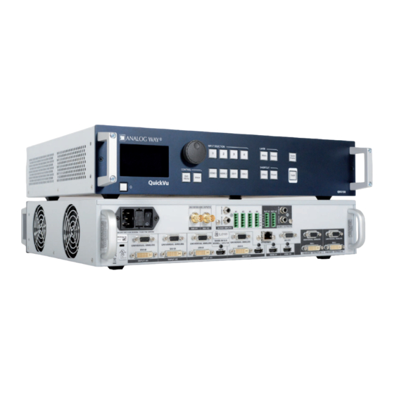
4.10.6 Status In order to permit quick identification of all the HDCP operations on the device, the QuickVu provides a full set of status summary to help the user with the HDCP management: - A front panel menu that displays all the general HDCP status of all inputs and outputs... - Page 22 5.1.1 Rear panel 5. CONNECTING THE QUICKVU 5.1 Description 5.1.1 Rear panel 1. Power supply: 100-240 VAC 2.5A 50/60HZ /FUSE F4A 250 VAC; internal, autoswitchable; 110W 2. 3G/HD/SD-SDI: SDI #1 to #2 3. S/PDIF: audio inputs #1 to #2 4. MCO male connector: for audio inputs (balanced) #1 to #4 5.
- Page 23 5.1.2 Front panel 5.1.2 Front panel 1. Front panel display: 4-line VFD 2. Menu scroll knob 3. Input selection: - 1 to 4: access source 1 to 4 - HDMI 1/2: access HDMI 1 or HDMI 2 - SDI 1 to SDI 2: access SDI 1 to SDI 2 4.
- Page 24 6. CONTROLLING THE QUICKVU The QuickVu can be controlled and operated either via the Front Panel, from your computer via the RCS², or via one of our Event Controllers. (Control of the QuickVu can also be integrated into automation and control systems, contact your local technical support for more details.)
- Page 25 - Check the IP address of both the device and the computer. It must have a unique IP address on the same network as your QuickVu. You may need to manually configure a static IP address for your computer in your computer’s network configuration.
- Page 26 6.3 RCS² top menu 6.3 RCS² top menu 6.3.1 Setup The Setup page is where you will review and modify the device configuration, such as output resolutions, input settings, and more. 6.3.2 Edit The Edit mode is the place where you will manage preset creation. You will make input selections, manage your inputs, adjust the layer attributes such as size, position, effect, etc.
-
Page 27: Operating Mode
7.1 Operating mode Before you start setting up your QuickVu for the first time, take some time to think about how you will be using it. The QuickVu offers one operating mode, which results in a versatile video production tool for live event staging and fixed installation applications. -
Page 28: Preset Mode
7.2.2 Audio 7.2.2 Audio In this section, you will setup the audio of your device, you have several modes. In all modes, you have the possibility to output the audio in AES3 or SPDIF: NO AUDIO: the audio of your device is switched off PRESET MODE: the standard mode of use of the device You have two possibilities:... -
Page 29: Freeze Mode
7.2.3 Screens 7.2.3 Screens In the screen configuration, you will find the state of your screen. It indicates the screen resolution, the maximum number of layers you can use. You will find configuration for the Quick Frame and the background color too. The Quick Frame will be your emergency frame that can be displayed in front of every layer. - Page 30 7.2.6 Output management 7.2.6 Output management Into the output section, you will be able to manage your output resolutions, formats, sync types, test patterns, etc. On the SETUP > OUTPUT TAB, the following screen will appear: A short summary of each output settings appears on the main page.
- Page 31 7.2.7 Input management Custom format The device offers the possibility to create your own output format: Choose CVT mode (restricted settings) or FULL mode (full settings) and start to create your format by adjusting the Horizontal Vertical pixels, frame rates and reduced blanking. Click on CHECK to verify if your format is a valid signal.
- Page 32 7.2.7 Input management - STATUS: format and size of the input, - CONTROL: Black: select Black to transform your input in a uniform color (black), Freeze: use this button to freeze the specific input, - EDID: choose the EDID for the selected plug. Under the HDCP section, you can: - Enable/disable the HDCP communication feature - Read the HDCP status, If the HDCP status says Active, this output connection is currently utilizing HDCP to...
- Page 33 The next tab is the USER FORMAT: In this tab, you can explicitly define the input format. The input format is automatically detected by the QuickVu but you can change it or force it. The available formats are close to the current one, in terms of lines.
-
Page 34: Invert Button
7.2.8 Frame management Keying setup can be done either by setting directly color references and tolerances or by using the color grab assistant. - INVERT BUTTON: at any time you can choose to invert the actual keying using this button. DSK TITLING: after your keying, the DSK titling feature allows you to play with the transparency of your deleted pixels. - Page 35 7.2.8 Frame management How to save a frame: Choose first Program or Preview, click on FREEZE if you want to freeze your output. Then click on EXECUTE to save your frame into the selected slot.
- Page 36 7.2.9 Audio management 7.2.9 Audio management The audio section permits the management of level, balance, and other audio settings for each input. Before modifying the audio settings, be sure to check the audio input mapping. Each video input has one audio source mapped to it.
-
Page 37: Digital Source
Depending on the device you will use after the analog way device, adjust carefully the analog gain. Basically, for a 0 level, the default value is 4 dBu. -
Page 38: Lcd Brightness
7.2.10 Service management 7.2.10 Service management Into the service section, you will find tools to warn you if the unit has a problem. Under TEMPERATURE, there is the alarm tab. If any fan FPGA or board are faulty, it will be displayed. TECHNICAL SUPPORT: Display the different technical support contacts depending on your area. - Page 39 7.3.1 Layer management 7.3 Edit 7.3.1 Layer management When you enter into the Edit menu, you will encounter by default this window. On this example, we have the Screen 1 Program and the Screen 1 Preview. The following example can be applied for any other output configurations.
- Page 40 7.3.2 Layer adjustments In this example, 2 inputs are affected to 2 layers into the Screen 1 Preview. The TAKE button on the bottom right side allows sending your configuration, made on the Preview screen, to the Program screen. With each press of the TAKE button, the Preview screen is transitioned to the Program screen. By default, PRESET TOGGLE mode is disabled.
- Page 41 7.3.3 Effects Position/Size Adjust the size horizontally (X) or vertically (Y), then adjust the width and the height of your layer. You can use the cursor or directly enter a value. To keep the aspect ratio by using the cursor, please enable the KEEP ASPECT RATIO button.
- Page 42 7.3.3 Effects After selecting the layout, the changes are applied on the selected screen. The size and position of all layers are updated. After applying a layout template, you can make further modifications to the layers before Taking your selections to Program. Layer position A layer position shortcut is also available.
-
Page 43: Reset Button
7.3.4 Preset load and save management 7.3.4 Preset load and save management Save a preset Once your preset is set up, you can store it into one of the 64 preset slots. To do that, click on SAVE MM and choose the number corresponding to the slot number. - Page 44 7.4 Live 7.4 Live The Live mode is designed for easy live operation of the device after you have created some presets. On the right, you will find all your saved presets under the tab called “MASTER MEMORIES”. A simple drag and drop on the screen will load your preset into the screen (Program or Preview).
- Page 45 Use the loop button to load again your timeline when it’s finished. Take a look at the global time of your timeline thanks to the clock on the right of the toolbar. Note: To control the QuickVu, Analog Way also provides Crestron and AMX modules. For more details, see appendices.
-
Page 46: Operating Through The Front Panel
8.1.2 Home menu Pressing the MENU button in the menu section of the QuickVu, will display and give you access to the following items on the menu VFD screen: - OUTPUT 1:... - Page 47 Analog Way engineers have developed a handy, user friendly way of identifying machine status on the front panel, via the use of color codes on the buttons of the machine. All new Analog Way machines use the same codes, for quick recognition of the status of any device of the range, at any given time.
-
Page 48: Output Status
HDCP status. 8.2.3 Source Output selection Once your inputs all have been configured, the output settings of the QuickVu must be set according to the machines plugged on your QuickVu Program and Preview outputs (video projector, Preview monitor...). - Page 49 8.2.4 Output selection settings - DVI as HDMI: DVI output content as HDMI. Audio is included, - HDCP DETECT: enable or not the HDCP detection on the output, - CENTERING PIC: display the centering test pattern, - TEST PATTERN: choose to display one of the available test pattern. All changes have to be validated by pressing the ENTER button in order to be saved NOTE: The output status can provide you all information about the output in real time.
-
Page 50: Settings Available
- There are not enough scalers for making a transition - All inputs are not locked on to scalers - All the necessary closing transitions are performed to free occupied scalers. The QuickVu locks on to new sources and performs all openings. - Page 51 8.2.10 Layer adjustment menu 8.2.10 Layer adjustment menu • To have access to the layer adjustment menu, a source has to be affected to your layer: Press Layer# button > Press source # • To adjust layers: Press Layer# button > Then go into Layer adjut menu Press TAKE to view the result on the Program screen 8.2.11 Layers with transitions Transitions...
- Page 52 Frames are mainly used as foregrounds in a typical show or event setup, and can be recorded from any of the QuickVu 8 sources and called back at the press of a single button. To use a Quick Frame, be sure first that it...
-
Page 53: Preset Mode
(#1 to #8) you wish to use as your “User Preset” (by default, the QuickVu will choose the next available preset in the QuickVu memory). By pressing the ENTER button, the QuickVu will ask you to confirm. Select Yes, your screen is memorized as a preset. - Page 54 8.2.17 Working with audio • Main audio/prelist audio: define the main or prelist audio settings: - PRESET MODE: ▪ Top layer: the sound on the output will follow the audio input of the top layer. ▪ Breakaway: when breakaway is activated, the audio on the output is memorized into the preset. A change of preset, changes the audio on the output.
- Page 55 - WORKING WITH DSK (Chroma / Luma key) • QuickVu allows to use a live source with green or blue (or any color) background and to key it over another live input, • Background is removed and replaced by another source, •...
- Page 56 8.2.18 Special features For Chroma Key: Chroma Keying is used to key from a particular color. It produces a key which is most suitable for moving images and “weatherman” style applications. - Color grabber: Select Chroma Key menu > Select Color grabber menu Using a crosshair, you can select a particular hue based on what is on screen.
-
Page 57: Mixer Mode
8.3 Menu tree 8.3 Menu tree MIXER MODE OUTPUT #1 FORMAT:1920X1080 RATE: 50.00HZ LOCK: INTERNAL | PROG.|PRVW. ---------+---------+---------- Layer1|Input1 |Input8 OUTPUT #2 FORMAT:1920X1080 RATE: 50.00HZ LOCK: INTERNAL... -
Page 58: Output1 / Output2
8.3 Menu tree OUTPUT1 / OUTPUT2 SYNC W/OUT1 (O1) (O1) Only for OUTPUT 2 (O2) For OUTPUT 2, only displayed when OUTPUT2 OUTPUT STATUS is not synchronized with OUTPUT1 (O3) Depending on the output format OUTPUT FORMAT (O2) (O4) Only for interlaced output format (O5) Only Computer and HDTV HDTV 720P HDTV 1035I... -
Page 59: Output Rate
8.3 Menu tree FORMAT CUSTOM 3 FORMAT CUSTOM 4 FORMAT CUSTOM 5 FORMAT CUSTOM 6 FORMAT CUSTOM 7 FORMAT CUSTOM 8 FORMAT CUSTOM 9 FORMAT CUSTOM 10 OUTPUT RATE (O2) INTERNAL REF 23.97HZ (O3) 24HZ (O3) 25HZ (O3) 29.97HZ (O3) (O3) 30HZ (O3) - Page 60 8.3 Menu tree GAMMA FLICKER FILTER (O4) ANALOG TYPE RGBS RGsB (SOG) RGB HV DVI TYPE AUTO RGB FULL (0-255) RGB LIMITED (16-235) DVI AS HDMI HDCP DETECTION CENTERING PIC TEST PATTERN V GREY SCALE H GREY SCALE V COLOR BAR H COLOR BAR GRID SMPTE...
- Page 61 8.3 Menu tree INPUTS CONFIG STATUS (I1) Displayed when input is a multiplug input. (I2) Displayed when a valid input signal is detected AUTOSET ALL (I3) Displayed when it is an analog plug and when the signal is computer HV type SYNC.
- Page 62 8.3 Menu tree ANALOG SETTINGS DVI-D SETTINGS SDI SETTINGS HDMI SETTINGS TYPE (I5) SDTV COMPOSITE AUTO (I6) SDTV YC (I6) NTSC VIDEO RGBS (I6) VIDEO RGsB (I6) SECAM VIDEO YUV (I6) COMPUTER SOG (I6) COMPUTER BW (I6) COMPUTER HV (I6) COMPUTER C TTL (I6) COMPUTER C ANA...
- Page 63 8.3 Menu tree LEFT CHANNEL RIGHT CHANNEL CHANNEL 1 CHANNEL 2 CHANNEL 3 CHANNEL 4 EDID (I8) EDID current preferred timing NONE 1920x1080 50Hz => Change 640X350 85HZ 640X400 85HZ 720X400 85HZ 640X480 59,94HZ 640X480 72HZ 640X480 75HZ 640X480 85HZ 720X480 59,94HZ 720X576 50HZ 800X600 50HZ...
- Page 64 8.3 Menu tree 1280X768 75HZ 1280X768 85HZ 1280X768 120HZ RB 1280X800 50HZ 1280X800 60HZ RB 1280X800 60HZ 1280X800 75HZ 1280X800 85HZ 1280X800 120HZ RB 1280X960 50HZ 1280X960 60HZ 1280X960 85HZ 1280X960 120HZ RB 1280X1024 50HZ 1280X1024 60HZ 1280X1024 75HZ 1280X1024 85HZ 1280X1024 120HZ RB 1360X768 50HZ 1360X768 60HZ...
- Page 65 8.3 Menu tree 1680X1050 60HZ RB 1680X1050 60HZ 1680X1050 75HZ 1680X1050 85HZ 1680X1050 120HZ RB 1920X1080 23,976HZ 1920X1080 24HZ 1920X1080 25HZ 1920X1080 29,97HZ 1920X1080 30HZ 1920X1080 50HZ 1920X1080 59,94HZ 1920X1080 60HZ 1920X1200 50HZ 1920X1200 60HZ RB 2048X1080 23,976HZ 2048X1080 24HZ 2048X1080 25HZ 2048X1080 29,97HZ 2048X1080 30HZ...
- Page 66 8.3 Menu tree ERASE PRESET PRESET MEMORY 1 (P1) PRESET MEMORY 2 (P1) PRESET MEMORY 3 (P1) PRESET MEMORY 4 (P1) PRESET MEMORY 5 (P1) PRESET MEMORY 6 (P1) PRESET MEMORY 7 (P1) PRESET MEMORY 8 (P1) EMPTY (P2) [...]...
- Page 67 8.3 Menu tree AUTO CENTERING IMAGE (G1) (G2) (G1) Displayed when a valid input is affected to a layer BLANKING ADJUST (G3) (G2) Displayed for computer analog signal, EDTV and HDTV analog video H POS (G3) Displayed for analog signal (G4) Displayed for computer analog signal V POS (G5) Displayed for video signal...
- Page 68 8.3 Menu tree ASPECT OUT CENTERED FULL SCREEN CROPPED SHARPNESS MEDIUM HIGH COLORIMETRY BRIGHTNESS CONTRAST COLOR COMPONENT LEVEL (G3) GREEN BLUE LOW LATENCY (G6) 2:2 PULLDOWN (G7) 3:2 PULLDOWN (G8) RESET SETTINGS RESET THE PLUG TO ITS DEFAULT VALUES? ->NO [...]...
- Page 69 8.3 Menu tree KEYING/TITLING TYPE (K1) Displayed when a valid input is affected to a layer (K2) Only displayed for Type = Luma key or Lumakey NONE +Titling (K3) Only displayed for Type = chroma key or chromakey LUMAKEY +Titling (K4) Only displayed for Type = Lumakey +Titling or CHROMAKEY Chromakey +Titling...
-
Page 70: Screen Settings
8.3 Menu tree SCREEN SETTINGS SCREEN 1 SCREEN 2 BACKGROUND COLOR GREEN BLUE QUICK FRAME FRAME 1 FRAME 2 FRAME 3 FRAME 4 FRAME 5 FRAME 6 FRAME 7 FRAME 8 AUTO TAKE PRESET TOGGLE [...]... - Page 71 8.3 Menu tree LAYER LAYER ADJUST (Y1) (Y1) Displayed when a valid input is affected to a layer H POS (Y3) Not available for frame (Y4) Only slide and wipe V POS (Y5) Only wipe HV POS HV SIZE H SIZE V SIZE LAYER ZOOM (Y3)
- Page 72 8.3 Menu tree BOTTOM TO TOP (Y4) TOP TO BOTTOM (Y4) VERTICAL FROM CENTER (Y5) HORIZONTAL FROM CENTER (Y6) HV FROM CENTER (Y6) FROM BOTTOM LEFT CORNER (Y7) FROM BOTTOM RIGHT CORNER (Y7) FROM TOP LEFT CORNER (Y7) FROM TOP RIGHT CORNER (Y7) EFFECT DURATION SMOOTH MOVE...
- Page 73 8.3 Menu tree FRAMES CAPTURE SOURCE (F1) Display “empty” is the slot is free (F2) Only displays valid frame list PROGRAM PREVIEW RECORD FRAMES FRAME 1 FRAME 2 [EMPTY] (F1) FRAME 3 FRAME 4 FRAME 5 [EMPTY] (F1) FRAME 6 [EMPTY] (F1) FRAME 7 FRAME 8...
-
Page 74: Audio Mode
8.3 Menu tree AUDIO AUDIO MODE (A1) Displayed if the audio mode is different of “no audio” NO AUDIO (A2) Displayed if the audio mode is “routing mode” (A3) Displayed if the audio mode is “Preset mode” PRESET MODE (A4) Displayed if the audio input is analog (A5) Displayed if the delay mode is manual ROUTING MODE SOURCE SETTINGS... - Page 75 8.3 Menu tree OUTPUT 1 (A2) OUPUT 2 (A2) MAIN AUDIO (A3) PRELIST AUDIO (A3) PRESETMODE (A3) BREAKAWAY TOP LAYER FOLLOW MASTER MUTE STEREO ANALOG LEVEL MASTER VOLUME BALANCE SOURCE NONE INPUT 1 INPUT 2 INPUT 3 INPUT 4 HDMI 1 HDMI 2 SDI 1 SDI 2...
- Page 76 8.3 Menu tree CONTROL VERSIONS VERS: 1.0.0 VARIABLE SET : 1 -------------------- CALIMERO MAIN MICRO : -------------------- CAMELYA DESIGN: SOFTWARE: IHS: TSTP: -------------------- FELINDRA DESIGN: SOFTWARE: IHS: TSTP: -------------------- TATIANA DESIGN: SOFTWARE: IHS: TSTP: [...]...
- Page 77 8.3 Menu tree CONNECTION (C1) Only displayed in UDP (C3) Displayed if at least one custom format is not valid RS232 / LAN (C3) Displayed if the custom format is valid (C4) Displayed if no custom formats are valid. RS232 RS232 BAUD RATE 1200 BAUDS 2400 BAUDS...
- Page 78 8.3 Menu tree STANDBY BAUD RATE SET MESSAGE ON SET MESSAGE OFF CLEAR MESSAGE ON CLEAR MESSAGE OFF STANDBY DATE/TIME YEAR MONTH HOUR MINUTE SECOND HDCP SUMMARY IN1 DVI-D: IDLE IN2 DVI-D: IDLE IN3 DVI-D: IDLE IN3 HDMI: IDLE IN4 DVI-D: IDLE IN4 HDMI: IDLE IN5 HDMI: IDLE IN6 HDMI: IDLE...
- Page 79 8.3 Menu tree RESET/ERASE RESET LAYERS RESET THE LAYERS POSITION AND SIZE? ->NO ERASE MEMORIES ERASE ALL THE IMAGE SETTINGS? ->NO ERASE PRESETS ERASE ALL THE PRESET MEMORIES? ->NO ERASE CUST.FRMT (C2) ERASE ALL THE CUSTOM FORMATS? ->NO COMPUT.CUSTOM1 (C3) COMPUT.CUSTOM2 (C3) COMPUT.CUSTOM3...
-
Page 80: Tech Support
8.3 Menu tree TECH. SUPPORT THE AMERICAS TECHSUPPORT@ANALOGWAYUSA.COM TEL: +1 212 269 1902 --------------------- EUROPE, MIDDLE EAST AND AFRICA TECHSUPPORT@ANALOGWAY.COM TEL: +33 (0)1 81 89 08 76 --------------------- ASIA, PACIFIC TECHSUPPORT@ANALOGWAYASIA.COM TEL: +65 6292 5800... -
Page 81: Maintenance And Support
9.1 Dashboard (RCS²) 9. MAINTENANCE AND SUPPORT 9.1 Dashboard (RCS²) On the RCS², you have access to a chart with general information on the unit. Please click on the Dashboard button: On this chart, you will find under the INFO tab, the Device name, the Serial number of your product, the actual firmware and the software version of the RCS². -
Page 82: Applications Note And Tips
HDMI output cannot be routed to a digital recording device. The QuickVu is fully HDCP compliant, meaning that you will be able to use the QuickVu to accept HDCP protected sources and route them to any HDCP protected outputs. As Analog Way is a licenced HDCP adoptor, this also means that the QuickVu is prevented from displaying any HDCP protected images on any non-HDCP compliant outputs (as is the case for all licenced HDCP compliant devices). -
Page 83: Warranty Conditions
• Analog Way’s direct employees are solely authorized to make this determination. • Analog Way reserves the right to refuse for repair and service a product for which the warranty is void. • In no way shall Analog Way be responsible for direct or indirect loss of profit or consequential damages resulting from any defect in this product. -
Page 84: Contact Information
UNITED STATES SINGAPORE SINGAPORE The Americas Europe, Middle East & Africa Asia Pacific Analog Way SAS - Headquarters Analog Way Inc. Analog Way Pte Ltd Tel.: +33 (0)1 81 89 08 60 Tel.: +1 212 269 1902 Tel.: +65 6292 5800... - Page 85 13.1 Crestron 2 & 3 series 13. APPENDICES 13.1 Crestron 2 & 3 series Midra™ Driver Using this driver, software developers and integrators can easily provide powerful solutions for remotely controlling any Midra™ series Switchers through Crestron 2-series or 3-series Control Systems®. The package includes: - The precompiled driver modules that can be used for recalling presets, selecting source inputs, changing PIP content, configuring audio inputs and outputs…,...
- Page 87 Follow us QVU150-03/31/2014 Pictures and drawings non-contractual. Specifications subject to change without prior notice.
Need help?
Do you have a question about the QuickVu and is the answer not in the manual?
Questions and answers