Table of Contents
Advertisement
Available languages
Available languages
Quick Links
™
(S-CUT 2)
User's Manual
Manuel Utilisateur
TABLE OF CONTENTS
SAFETY INSTRUCTIONS ...........................................................................................................................................................2
Chapter 1 : INTRODUCTION .......................................................................................................................................................5
Chapter 2 : INSTALLATION ........................................................................................................................................................6
Chapter 3 : TECHNICAL DESCRIPTION....................................................................................................................................7
Chapter 4 : STARTING .................................................................................................................................................................8
Chapter 5 : OPERATING MODE................................................................................................................................................12
Chapter 6 : LCD SCREEN DESCRIPTION ................................................................................................................................15
Chapter 7 : LCD FUNCTIONS DESCRIPTION .........................................................................................................................17
Chapter 8 : TECHNICAL SPECIFICATIONS ............................................................................................................................21
Chapter 9 : CONTROL SOFTWARE..........................................................................................................................................23
Chapter 10 : RS-232 PROGRAMMER'S GUIDE .......................................................................................................................28
WARRANTY...............................................................................................................................................................................75
TABLE DES MATIÈRES
INSTRUCTIONS DE SÉCURITÉ.................................................................................................................................................3
Chapitre 1 : INTRODUCTION....................................................................................................................................................40
Chapitre 2 : MONTAGE ..............................................................................................................................................................41
Chapitre 3 : DESCRIPTION TECHNIQUE ................................................................................................................................42
Chapitre 4 : MISE EN SERVICE.................................................................................................................................................43
Chapitre 5 : MODE OPÉRATOIRE.............................................................................................................................................47
Chapitre 6 : DESCRIPTION DE L'ÉCRAN LCD .......................................................................................................................50
Chapitre 7 : DESCRIPTION DES FONCTIONS DE L'ÉCRAN LCD........................................................................................52
Chapitre 8 : SPÉCIFICATIONS TECHNIQUES ........................................................................................................................56
Chapitre 9 : UTILISATION DU LOGICIEL ...............................................................................................................................58
Chapitre 10 : GUIDE DE PROGRAMMATION RS-232............................................................................................................63
GARANTIE .................................................................................................................................................................................75
®
ANALOG WAY
SMART CUT 2™
EDITION : 10/02
.
Advertisement
Table of Contents

Related Manuals for Analog way Smart Cut 2


Summary of Contents for Analog way Smart Cut 2
-
Page 1: Table Of Contents
™ SMART CUT 2 (S-CUT 2) User’s Manual Manuel Utilisateur TABLE OF CONTENTS SAFETY INSTRUCTIONS ................................2 Chapter 1 : INTRODUCTION ...............................5 Chapter 2 : INSTALLATION ................................6 Chapter 3 : TECHNICAL DESCRIPTION............................7 Chapter 4 : STARTING .................................8 Chapter 5 : OPERATING MODE..............................12 Chapter 6 : LCD SCREEN DESCRIPTION ..........................15... -
Page 2: Safety Instructions
SMART CUT 2™ SAFETY INSTRUCTIONS All of the safety and operating instructions should be read before the product is operated and should be retained for further reference. Please follow all of the warnings on this product and its operating instructions. -
Page 3: Instructions De Sécurité
SMART CUT 2™ INSTRUCTIONS DE SÉCURITÉ Afin de mieux comprendre le fonctionnement de cet appareil nous vous conseillons de bien lire toutes les consignes de sécurité et de fonctionnement de l’appareil avant utilisation. Conserver les instructions de sécurité et de fonctionnement afin de pouvoir les consulter ultérieurement. Respecter toutes les consignes marquées dans la documentation, sur le produit et sur ce document. -
Page 4: Instrucciones De Seguridad
SMART CUT 2™ SICHERHEITSHINWEISE Um den Betrieb dieses Geräts zu verstehen, raten wir Ihnen vor der Inbetriebnahme alle Sicherheits und Betriebsanweisungen genau zu lesen. Diese Sicherheits- und Betriebsanweisungen für einen späteren Gebrauch sicher aufbewahren. Alle in den Unterlagen, an dem Gerät und hier angegebenen Sicherheitsanweisungen einhalten. -
Page 5: Chapter 1 : Introduction
Each VIDEO source is scaled and genlocked to match the resolution of your COMPUTER from 640 x 480 up to 1280 x 1024. The SMART CUT 2™ offers a clean and fast switching with no glitch between : - any VIDEO and 1 COMPUTER source (in seamless mode), - VIDEO sources (with a fast "Black Cut"),... -
Page 6: Chapter 2 : Installation
SMART CUT 2 into a 19” rack : ™ Screw the supplied 19” brackets to the sides of the SMART CUT 2 ™ Attach the SMART CUT 2 to the rack by using 4 screws in the front panel holes (screws not included). -
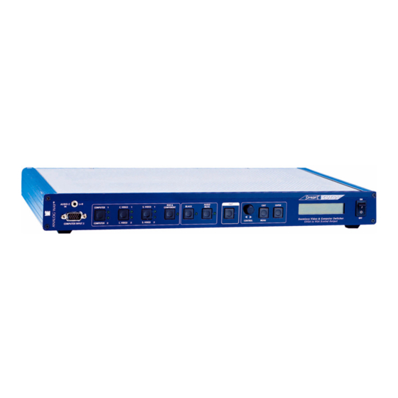
Page 7: Chapter 3 : Technical Description
SMART CUT 2™ Chapter 3 : TECHNICAL DESCRIPTION Chapter 3 : TECHNICAL DESCRIPTION 3-1. FRONT PANEL COMPUTER INPUT 2: COMPUTER #2 (PC, MAC, WORKSTATION) input on HD15 female connector. AUDIO-2 IN L+R: COMPUTER #2 audio stereo input on 3.5 JACK connector. -
Page 8: Chapter 4 : Starting
Turn OFF all of your equipment before connecting. ™ Connect the AC Power supply cord to the SMART CUT 2 and to an AC power outlet. Connect your video sources (VCR, DVD, camera, laser disc, ...) to the C.V1, C.V2, S.VIDEO 1, S.VIDEO 2 and RGB/S &... - Page 9 SMART CUT 2™ Chapter 4 : STARTING 4-2. COMPOSITE VIDEO INPUTS (C.V1 & C.V2) The Composite Video signal, usually called COMPOSITE or VIDEO, is available on most video equipment (VCR, DVD, CAMERA…), but it is also the lowest in picture quality. The video standard of this signal could be NTSC, PAL or SECAM.
- Page 10 4-5. COMPUTER INPUTS ™ The SMART CUT 2 is provided with two COMPUTER inputs: COMPUTER 1 (in rear panel) and COMPUTER 2 (in front panel). These inputs are used to pass-through any COMPUTER signals. In SEAMLESS mode, the signal connected to one of the 2 inputs is used as the "reference".
- Page 11 RGBHV (H & V Separate Sync.) or an RGB/S (Composite Sync.) output signal. If ™ your display device only accepts Composite Sync., connect the C.SYNC. cable to the H BNC of the SMART CUT 2 and select COMP (Composite Sync.) in the LCD menu # 2-1.
-
Page 12: Chapter 5 : Operating Mode
5-1. THE SEAMLESS MODE • SETTINGS ™ We recommend to reset the SMART CUT 2 to all of its default values, with the LCD menu # 5-6, before proceeding. Select the output Sync. type which corresponds to your display device (LCD menu # 2-1). - Page 13 NOTE: If the 2 COMPUTER inputs are used you must adjust your display device for both COMPUTER. • IMAGE ADJUSTMENTS ™ For each input source connected to the SMART CUT 2 , do the following adjustments: Adjust the position and size with the LCD menus (#3-1, #3-2, #3-3, #3-4).
- Page 14 5-3. THE SCALER FOLLOW MODE • SETTINGS ™ We recommend to reset the SMART CUT 2 to all of its default values, with the LCD menu # 5-6, before proceeding. Select the output Sync. type which corresponds to your display device (LCD menu # 2-1).
-
Page 15: Chapter 6 : Lcd Screen Description
• The STATUS MODE indicates the input and output status of the SMART CUT 2 ™ • The CONTROL MODE allows to select and adjust the parameters of the SMART CUT 2 6-2. CONTROL BUTTONS The LCD screen is controlled by 3 buttons : CONTROL knob: To scroll thru the different menus. - Page 16 Chapter 6 : LCD SCREEN DESCRIPTION SMART CUT 2™ 6-4. CONTROL MODE The menus of the CONTROL MODE are configured as follow : 1 input menu 1 video standard video standard auto manual c.video 1 auto c.video 2 NTSC 2 video status The LCD displays the s.video 1...
-
Page 17: Chapter 7 : Lcd Functions Description
, the LCD window displays all of the C.VIDEO & S.VIDEO inputs. The inputs preceded by EXTEND (Example : EXTEND CV2) are ™ the inputs directly connected to the SMART CUT 2 [video status] + ENTER. Indicates the status of the selected video input. - Page 18 + ENTER. ™ NOTE : If a SMART SWITCH VIDEO is connected to the SMART CUT 2 ™, the LCD window displays : ™ • [COMPUTER 1] = SMART CUT 2 is in Seamless mode. The output is synchronized on Computer 1.
- Page 19 SMART CUT 2™ Chapter 7 : LCD FUNCTIONS DESCRIPTION 3 [IMAGE MENU] + ENTER. NOTE: This menu is active only on the displayed video source. This menu is not available for the COMPUTER inputs. The image settings and adjustments can be different and memorized for each video input.
- Page 20 Select this function if you use a SMART SWITCH VIDEO (SMV415) and/or a SMART SWITCH AUDIO ™ (SMA415) connected to your SMART CUT 2 • [NO] = No SMART SWITCH connected to the SMART CUT 2 ™ ™ • [YES] = SMART SWITCH connected to the SMART CUT 2 [version] + ENTER.
-
Page 21: Chapter 8 : Technical Specifications
SMART CUT 2™ Chapter 8 : TECHNICAL SPECIFICATIONS Chapter 8 : TECHNICAL SPECIFICATIONS 8-1. VIDEO INPUTS • RGB/S (4 BNC connectors) 15.625 kHz / 50 Hz ..15.735 kHz / 60 Hz (625L ..525L). Levels: R, G, B = 3 x 0.7 Vp/p. - Page 22 Chapter 8 : TECHNICAL SPECIFICATIONS SMART CUT 2™ 8-3. AUDIO INPUTS 7 stereo inputs : Video = Balanced and unbalanced inputs. Computer = Unbalanced inputs. Vi = +4 dBm Max. Zi = 22 kΩ unbalanced. Zi = 44 kΩ balanced.
-
Page 23: Chapter 9 : Control Software
(DB 9 Female / DB 9 Male). S-CUT2 ™ NOTE : The Remote Keypad (RK20) is not compatible when the SMART CUT 2 is used with the SMV415. • If you use the SMART CUT 2 ™... - Page 24 Connect the RS-232 cables between the control device and the SMART CUT 2 as indicated in section 9-1. Then only power ON all of the devices. Click on the program files S-CUT 2 in Start-program-ANALOGWAY-SMART CUT 2 to run the software. Click on Control menu and select the Serial port. ™...
- Page 25 Select the Serial Port in the Controls menu. ™ The SMART CUT 2 is now connected to the computer ; make a Reset to default value (Controls menu) if necessary. In the Input menu, select the video type for the RGB / YUV input, and select the video standard for all of the other video inputs.
- Page 26 Chapter 9 : CONTROL SOFTWARE SMART CUT 2™ 9-3. SOFTWARE SET UP (continued) In the Output menu, select the output Sync. type (Sync.) and the Reference sync. If Reference Sync. = no computer, select the output format (Format) and the Output frame rate.
- Page 27 ™ ™ When a SMART SWITCH VIDEO is connected to the SMART CUT 2 , select Extend Switch in the Controls menu. Then the software display the following window. Then make all of yours adjustments as indicated in this section in...
-
Page 28: Chapter 10 : Rs-232 Programmer's Guide
™ If the command cannot be executed (value out of range, no signal on the selected input), the SMART CUT 2 will just sends back the current status of the corresponding parameters. - Page 29 SMART CUT 2™ Chapter 10 : RS-232 PROGRAMMER'S GUIDE 10-4. COMMANDS AND RESPONSES TABLE The following table resumes commands which are recognized as valid and the responses that will be returned to the control device (on RS-232 port). VALUE EXAMPLE...
- Page 30 Chapter 10 : RS-232 PROGRAMMER'S GUIDE SMART CUT 2™ 10-4. COMMANDS AND RESPONSES TABLE (continued) VALUE EXAMPLE COMMAND COMMAND RESPONSE ASCII DESCRIPTION COMMAND RESPONSE ACTION EXPLANATION STATUTS COMMANDS (READ ONLY) 65535 UNIT MEASURES UNITY IN kHz. UNIT---- READ UNITY OF MEASURE.
- Page 31 SMART CUT 2™ Chapter 10 : RS-232 PROGRAMMER'S GUIDE 10-5. COMMANDS DESCRIPTION (continued) INPUT COMMANDS • i command is used to pre-select an input. ™ - SMART CUT 2 ALONE APPLICATION DECIMAL VALUE INPUT # SELECTION RESPONSE APPLICATION BLACK IPRES0...
- Page 32 SMART CUT 2™ 10-5. COMMANDS DESCRIPTION (continued) • m command is used to select the C.VIDEO & S.VIDEO mode (front panel of the SMA415 & SMV415). ™ ™ - SMART CUT 2 + SMART SWITCH VIDEO APPLICATION DECIMAL SELECTION RESPONSE...
- Page 33 SMART CUT 2™ Chapter 10 : RS-232 PROGRAMMER'S GUIDE 10-5. COMMANDS DESCRIPTION (continued) OUTPUT COMMANDS • u command is used to select the reference sync. ™ - SMART CUT 2 ALONE APPLICATION. DECIMAL SELECTION RESPONSE APPLICATION VALUE INTERNAL RATE SSYNC0...
- Page 34 • H, V, W, S, B, C, s, T, commands are used to control the output adjustments. 0 = minimum 255 = maximum • f command is used to select the image process. ™ ™ - SMART CUT 2 WITH OR WITHOUT SMART SWITCH VIDEO APPLICATION. DECIMAL SELECTION (IMAGE PROCESS) RESPONSE...
- Page 35 SMART CUT 2™ Chapter 10 : RS-232 PROGRAMMER'S GUIDE 10-5. COMMANDS DESCRIPTION (continued) ™ ™ - SMART CUT 2 + SMART SWITCH AUDIO APPLICATION. DECIMAL INPUT # SELECTION RESPONSE APPLICATION VALUE AUTOMATIC ACHAN0 EXTEND PC 2 ACHAN2 EXTEND C.VIDEO 2 ACHAN4 EXTEND S.VIDEO 2...
- Page 36 0 = Computer format out of range (for reference sync.) 1 = Computer format in range (can be used as reference sync.) • c command is used to know the computer number which status is displayed. ™ - SMART CUT 2 ALONE APPLICATION. DECIMAL SELECTION...
- Page 37 60 Hz VSTA16 4.43 60 Hz VSTA8 • v command is used to know the number of the video input which status is displayed. ™ - SMART CUT 2 ALONE APPLICATION. DECIMAL STATUS OF VIDEO # RESPONSE APPLICATION VALUE NO VIDEO SELECTED VCHAN0 C.VIDEO 1...
- Page 38 10-5. COMMANDS DESCRIPTION (continued) MISCELLANEOUS COMMANDS ™ ™ - SMART CUT 2 with or without SMART SWITCH VIDEO APPLICATION. • Y command is used to control the CUT, the AUDIO MUTE, the RESET TO DEFAULT VALUE, the FRONT PANEL LOCK, the FREEZE…(RESPONSE : CMD----).
- Page 39 SMART CUT 2™ Chapter 10 : RS-232 PROGRAMMER'S GUIDE 10-6. ASCII / HEX / DEC TABLE ASCII ASCII ASCII space " & ’ < > PAGE 39...
-
Page 40: Chapitre 1 : Introduction
™ S-CUT 2-M-DILA SMART CUT 2 avec interface RS-232 et format de sortie D-ILA optionnels. OPT-ROOM-1 Sortie optionnelle "ROOM CONTROL". ™ 1-4. RÉFÉRENCES DES ACCESSOIRES OPTIONNELS DU SMART CUT 2 REFERENCES DESIGNATIONS RK20 Remote KEYPAD pour S-CUT 2-M. ™ SMV415 SMART SWITCH VIDEO : permet d'étendre à... -
Page 41: Chapitre 2 : Montage
• Les ouvertures dans le capot supérieur et dans la face arrière sont utilisées pour le IMPORTANT: refroidissement de l’appareil. Ne pas bloquer ces ouvertures. • Assurez vous qu’aucun poids dépassant 2 kg ne soit posé sur le SMART CUT 2 ™ • La température ambiante maximale ne doit pas dépasser 40°C (104°F). -
Page 42: Chapitre 3 : Description Technique
Chapitre 3 : DESCRIPTION TECHNIQUE SMART CUT 2™ Chapitre 3 : DESCRIPTION TECHNIQUE 3-1. FACE AVANT COMPUTER INPUT 2: Entrée informatique n°2 (PC, MAC, station de travail) sur connecteur HD15 F. AUDIO-2 IN L+R: Entrée audio stéréo de l'entrée informatique n°2 (COMPUTER 2) sur jack 3,5 mm. -
Page 43: Chapitre 4 : Mise En Service
Eteignez tous les appareils avant d’effectuer les raccordements. ™ Raccordez le cordon secteur à l’entrée secteur du SMART CUT 2 et à une prise secteur. Raccordez vos sources vidéo (Magnétoscope, lecteur de DVD, caméra, ...) sur les entrées "C.V 1, C.V 2, S.VIDEO 1, S.VIDEO 2 et RGB.S / COMPONENT (R-Y, Y, B-Y)". - Page 44 Chapitre 4 : MISE EN SERVICE SMART CUT 2™ 4-2. ENTRÉES VIDEO COMPOSITE (C.V1 et C.V2) Le signal Vidéo Composite, aussi appelé COMPOSITE ou VIDEO, est disponible sur la plupart des appareils vidéo (Magnétoscope , DVD, Caméra…), mais c’est aussi celui qui procure la moins bonne qualité d’image. Le standard vidéo de ce signal peut être PAL, SECAM ou NTSC.
- Page 45 4-5. ENTRÉES "COMPUTER INPUT" ™ Le SMART CUT 2 est équipé de deux entrées informatique: COMPUTER 1 (en face arrière) et COMPUTER 2 (en face avant). Ces entrées permettent de raccorder des signaux informatique qui seront directement transmis sur la sortie "DISPLAY OUTPUT".
- Page 46 SMART CUT 2™ 4-6. SORTIE "DISPLAY OUTPUT" ™ Le SMART CUT 2 est équipé d’une sortie sur 5 connecteurs BNC. Si votre afficheur est uniquement équipé d’un connecteur HD15, utiliser le câble BNC (x5) vers HD15 fourni (Voir schéma ci dessous).
-
Page 47: Chapitre 5 : Mode Opératoire
Chapitre 5 : MODE OPÉRATOIRE Chapitre 5 : MODE OPÉRATOIRE ™ Le SMART CUT 2 peut être utilisé dans 3 modes de synchronisation différent. • Le MODE SEAMLESS, permet de commuter entre l'ordinateur "référencé" et les autres entrées vidéo sans décrochage de l'image projetée. - Page 48 NOTE: Si les 2 entrées COMPUTER sont utilisées vous devez réglez votre afficheur pour les 2 ordinateurs. • RÉGLAGES D'IMAGE ™ Pour chaque source raccordée au SMART CUT 2 , effectuer les réglages suivants: Réglez la position et la taille avec les menus de l'écran (3-1, 3-2, 3-3, 3-4).
- Page 49 Présentation vidéo et informatique. Présentation vidéo (image Films et affichages d'images statiques). animées. ™ SYNCHRONISATION Référencée sur une entrée Générée par le SMART CUT 2 Référencée sur l'entrée vidéo informatique (Computer 1 ou sélectionnée (50 Hz si PAL ou Computer 2). SECAM, 59,94 Hz si NTSC).
-
Page 50: Chapitre 6 : Description De L'écran Lcd
L'écran LCD est composé de 2 modes : le mode ÉTAT et le mode RÉGLAGE. ™ • Le MODE ÉTAT indique l'état de l'entrée sélectionnée et l'état de la sortie du SMART CUT 2 ™ • Le MODE RÉGLAGE permet de sélectionner et d'ajuster les paramètres du SMART CUT 2 6-2. - Page 51 SMART CUT 2™ Chapitre 6 : DESCRIPTION DE L'ÉCRAN LCD 6-4. MODE RÉGLAGE Les menus du MODE RÉGLAGE sont configurés comme ci dessous : 1 input menu 1 video standard video standard auto manual c.video 1 auto c.video 2 NTSC 2 video status L'écran LCD affiche l'état...
-
Page 52: Chapitre 7 : Description Des Fonctions De L'écran Lcd
, l'écran LCD affiche toutes les entrées C.VIDEO & S.VIDEO. Les entrées précédées par la lettre EXTEND (Exemple : EXTEND ™ CV2) sont les entrées directement raccordées au SMART CUT 2 [video status] + ENTER Indique l’état de l’entrée vidéo sélectionnée. - Page 53 + ENTER. ™ NOTE : Si un SMART SWITCH VIDEO est raccordé au SMART CUT 2™, l'écran LCD affiche : • [COMPUTER 1] = Le SMART CUT 2 ™ est en mode Seamless. La sortie est synchronisée sur Computer 1.
- Page 54 Chapitre 7 : DESCRIPTION DES FONCTIONS DE L'ÉCRAN LCD SMART CUT 2™ 3 [IMAGE MENU] + ENTER NOTE: Ce menu est actif uniquement pour l’entrée vidéo sélectionnée. Ce menu n’est pas disponible pour les entrées COMPUTER. Les réglages suivants peuvent ainsi être mémorisés différemment pour chacune des entrées vidéo.
- Page 55 (SMV415) et/ou un SMART SWITCH ™ ™ AUDIO (SMA415) raccordés au SMART CUT 2 • [NO] = Pas de SMART SWITCH raccordé au SMART CUT 2 ™ • [YES] = SMART SWITCH raccordé au SMART CUT 2 ™ [version] + ENTER État de la version interne de l’appareil : K = xxxx...
-
Page 56: Chapitre 8 : Spécifications Techniques
Chapitre 8 : SPÉCIFICATIONS TECHNIQUES SMART CUT 2™ Chapitre 8 : SPÉCIFICATIONS TECHNIQUES 8-1. ENTRÉES VIDÉO • RGB/S (4 connecteurs BNC). 15,625 kHz / 50 Hz ..15,735 kHz / 60 Hz (625L ..525L). Niveaux: R, G, B = 3 x 0,7 Vc/c. - Page 57 SMART CUT 2™ Chapitre 8 : SPÉCIFICATIONS TECHNIQUES 8-3. ENTRÉES "AUDIO INPUTS" 7 entrées stéréo: Vidéo = Entrées symétriques ou asymétriques. Computer = Entrées asymétriques. Vi = +4 dBm Max. Zi = 22 kΩ asymétriques. Zi = 44 kΩ symétriques.
-
Page 58: Chapitre 9 : Utilisation Du Logiciel
CONTROL (RS-232) (DB 9 Femelle) du SMART CUT 2 avec un câble droit (DB 9 Femelle / DB 9 Mâle). S-CUT 2 ™ NOTE: Le Remote Keypad (RK20) n'est pas compatible lorsque le SMART CUT 2 est utilisé avec le SMV415. ™... - Page 59 CUT 2 remote control. • DÉMARRAGE: ™ Raccordez le câble RS-232 entre l'unité de contrôle et le SMART CUT 2 comme indiqué dans la section 9-1. Mettez ensuite tous les appareils sous tension. Cliquez sur le fichier S-CUT 2 dans le menu Démarrer-programmes-ANALOGWAY-SMART CUT 2 pour démarrer le logiciel.
- Page 60 9-3. ÉCRANS DE CONTRÔLE Sélectionnez le Port Série (Serial Port) dans le menu Controls. ™ Le SMART CUT 2 est maintenant connecté à l’ordinateur; effectuez un Reset to default values (menu Controls) si nécessaire. Dans le menu Input, sélectionnez le type de vidéo pour l’entrée RGB / YUV, et sélectionnez le standard vidéo pour toutes les autres entrées vidéo.
- Page 61 SMART CUT 2™ Chapitre 9 : UTILISATION DU LOGICIEL 9-3. ÉCRANS DE CONTRÔLE (suite) Dans le menu Output sélectionnez le type de Synchro de sortie (Output sync.), et le mode de synchronisation (Reference sync). Si Reference sync = no computer, sélectionnez le format de sortie (Format) et le mode de synchronisation de la trame (Output frame rate).
- Page 62 NOTE: Sélectionnez Automatic pour une commutation audio follow. ™ ™ Lorsqu' un SMART SWITCH VIDEO est raccordé au SMART CUT 2 , sélectionnez Extend Switch dans le menu Controls. Le logiciel affichera alors la fenêtre suivante. Effectuez ensuite tous les réglages comme indiqué dans les sections...
-
Page 63: Chapitre 10 : Guide De Programmation Rs-232
"ENTER" du clavier. Une commande peut être précédée d'une valeur (voir 10-2 STRUCTURE D'UNE COMMANDE). ™ Lorsque le SMART CUT 2 reçoit une commande valide, il exécute cette commande puis renvoie à l’appareil de contrôle l'état de tous les paramètres qui ont été modifié suite à l'envoie de cette commande. - Page 64 Chapitre 10 : GUIDE DE PROGRAMMATION RS-232 SMART CUT 2™ 10-4. TABLEAU DES COMMANDES ET RÉPONSES Le tableau suivant résume les commandes qui sont reconnues comme valable et les réponses qui seront retournées à l’unité. COMMANDE REPONSE DESCRIPTION DE VALEUR...
- Page 65 SMART CUT 2™ Chapitre 10 : GUIDE DE PROGRAMMATION RS-232 10-4. TABLEAU DES COMMANDES ET RÉPONSES (suite) COMMANDE REPONSE DESCRIPTION DE VALEUR EXEMPLE ASCII LA COMMANDE COMMANDE REPONSE EXPLICATION COMMANDES D’ÉTAT (LECTURE UNIQUEMENT) UNIT MESURE L’UNITÉ EN KHz. 65535 UNIT---- DONNE L’UNITE DE MESURE...
- Page 66 Chapitre 10 : GUIDE DE PROGRAMMATION RS-232 SMART CUT 2™ 10-5. DESCRIPTION DES COMMANDES (suite) COMMANDES D’ENTRÉE • La commande i est utilisée pour présélectionner une entrée. ™ - APPLICATION SMART CUT 2 SEUL. VALEUR DECIMALE SÉLECTION DE RÉPONSE APPLICATION L’ENTRÉE...
- Page 67 Chapitre 10 : GUIDE DE PROGRAMMATION RS-232 10-5. DESCRIPTION DES COMMANDES (suite) • La commande m est utilisée pour sélectionner le mode C.VIDEO & S.VIDEO (face avant du SMA415 et SMV415). ™ ™ - APPLICATION SMART CUT 2 + SMART SWITCH VIDEO VALEUR SÉLECTION RÉPONSE...
- Page 68 Chapitre 10 : GUIDE DE PROGRAMMATION RS-232 SMART CUT 2™ 10-5. DESCRIPTION DES COMMANDES (suite) COMMANDES DE SORTIE • La commande u est utilisée pour sélectionner la référence de Synchro. ™ - APPLICATION SMART CUT 2 SEUL VALEUR DECIMALE SÉLECTION RÉPONSE APPLICATION...
- Page 69 • Les commandes M et a sont utilisées pour régler l’audio (MASTER VOLUME & AUDIO LEVEL). 0 = minimum 255 = maximum. • La commande A est utilisée pour sélectionner la voie audio. ™ - APPLICATION SMART CUT 2 SEUL. VALEUR DECIMALE SÉLECTION DE L’ENTRÉE RÉPONSE...
- Page 70 Chapitre 10 : GUIDE DE PROGRAMMATION RS-232 SMART CUT 2™ 10-5. DESCRIPTION DES COMMANDES (suite) ™ ™ ™ - APPLICATION SMART CUT 2 + SMART SWITCH AUDIO + SMART SWITCH VIDEO VALEUR DECIMALE SÉLECTION DE L’ENTRÉE RÉPONSE APPLICATION AUTOMATIQUE ACHAN0...
- Page 71 SÉLECTION RÉPONSE APPLICATION NO COMPUTER CCHAN0 S-CUT 2 COMPUTER 1 CCHAN1 SEUL COMPUTER 2 CCHAN2 - APPLICATION SMART CUT 2™ + SMART SWITCH VIDEO™ VALEUR DECIMALE SÉLECTION RÉPONSE APPLICATION NO COMPUTER CCHAN0 EXTEND PC 2 CCHAN2 S-CUT 2 COMPUTER 1...
- Page 72 Chapitre 10 : GUIDE DE PROGRAMMATION RS-232 SMART CUT 2™ 10-5. DESCRIPTION DES COMMANDES (suite) • La commande v est utilisée pour connaître l’entrée vidéo dont l’état est affiché. ™ - APPLICATION SMART CUT 2 SEUL. VALEUR DECIMALE ÉTAT DE LA VIDÉO RÉPONSE...
- Page 73 SMART CUT 2™ Chapitre 10 : GUIDE DE PROGRAMMATION RS-232 10-5. DESCRIPTION DES COMMANDES (suite) COMMANDES DIVERSES • La commande Y est utilisée pour commander les fonctions : CUT, AUDIO MUTE, DEFAULT VALUE, FRONT PANEL LOCK, FREEZE…(REPONSE : CMD----). Bit 11...
- Page 74 Chapitre 10 : GUIDE DE PROGRAMMATION RS-232 SMART CUT 2™ 10-6. TABLEAU ASCII / HEX / DEC ASCII ASCII ASCII space " & ’ < > PAGE 74...
-
Page 75: Warranty
In case of any problem, get the serial number of the unit, a description of the problem, and then call your authorized dealer. GARANTIE Analog Way garantie le produit contre les défauts matériels et vices de fabrication, pour une période de 3 ans à partir de la date d'achat (retour en nos locaux).
Need help?
Do you have a question about the Smart Cut 2 and is the answer not in the manual?
Questions and answers