Libelium Waspmote Technical Manual
Hide thumbs
Also See for Waspmote:
- Technical manual (171 pages) ,
- Manual (39 pages) ,
- Quick start manual (27 pages)
Table of Contents
Advertisement
Quick Links
Advertisement
Table of Contents

Subscribe to Our Youtube Channel
Related Manuals for Libelium Waspmote


Summary of Contents for Libelium Waspmote
- Page 1 Waspmote Technical Guide...
-
Page 2: Table Of Contents
Document version: v8.2 - 02/2019 © Libelium Comunicaciones Distribuidas S.L. INDEX 1. Introduction .......................... 6 2. Waspmote Kit ........................7 2.1. General and safety information ...................... 7 2.2. Conditions of use ..........................8 2.3. Assembly ............................10 3.2. General view ............................ 16 3.2.1. - Page 3 5. Architecture and system ....................64 5.1. Concepts ............................64 5.2. Timers ............................... 65 5.2.1. Watchdog ..........................65 5.2.2. RTC Watchdog for reseting Waspmote ................65 5.2.3. RTC ............................66 6. Interruptions ........................67 7. Energy system ........................68 7.1. Concepts ............................68 7.2.
-
Page 4: Index
Index 12. Sigfox modules ........................94 13. WiFi PRO module ....................... 96 14. Bluetooth Pro module ...................... 97 15. Bluetooth Low Energy module ..................99 16. GPRS module ........................101 17. 3G module ........................102 18. 4G module ........................103 19. - Page 5 Index 30. Interacting with Waspmote ................... 131 30.1. Receiving XBee frames with Waspmote Gateway ..............131 30.1.1. Waspmote Gateway ....................... 131 30.1.2. Linux receiver ......................... 132 30.1.3. Windows receiver ......................136 30.1.4. Mac-OS receiver ......................138 31. Meshlium - The IoT Gateway ..................139 31.1.
-
Page 6: Introduction
Introduction 1. Introduction This guide explains the features related to our product line Waspmote v15, released on October 2016. If you are using previous versions of our products, please use the corresponding guides, available on our Development website. You can get more information about the generation change on the document “New generation of Libelium product... -
Page 7: Waspmote Kit
All documents and any examples they contain are provided as-is and are subject to change without notice. • Except to the extent prohibited by law, Libelium makes no express or implied representation or warranty of any kind with regard to the documents, and specifically disclaims the implied warranties and conditions of merchantability and fitness for a particular purpose. -
Page 8: Conditions Of Use
• the SD card could be damaged. Micro SD card: Waspmote must not be switched off or reseted while there are ongoing read or write opera- • tions in the SD card. Otherwise, the SD card could be damaged and data could be lost. - Page 9 Only use the non-rechargeable batteries with the Waspmote units specifically prepared for them (identified with a pink sticker on them). The reason is, a regular Waspmote will try to inject current in the non-rechargeable battery if the USB or the solar panel is connected. This is dangerous for the good working of a non-rechargeable battery.
-
Page 10: Assembly
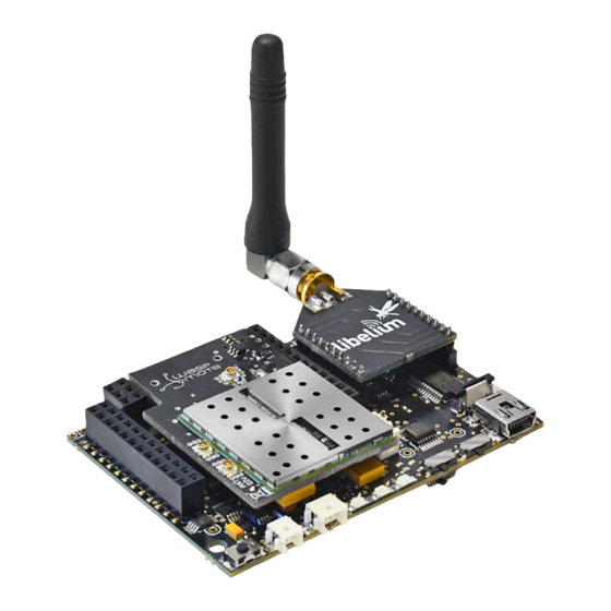
Waspmote Kit 2.3. Assembly Connect the antenna to the wireless module • Place the wireless module in Waspmote • Place the wireless module in Waspmote Gateway • -10- v8.2... - Page 11 Waspmote Kit Connect the antenna in the GPRS module • Place the GPRS module in Waspmote • Place the SD card in Waspmote • -11- v8.2...
- Page 12 Waspmote Kit Connect the battery in Waspmote • Connect the sensor board • Switch it on • -12- v8.2...
- Page 13 Waspmote Kit Waspmote battery disconnection • Use the pick supplied by Libelium in order to disconnect Waspmote battery. Insert the pick on the slot of the battery connector and pull straight out. Do not pull the battery cables. -13- v8.2...
- Page 14 Waspmote Kit Battery handling instructions • In order to prevent from cable breaking, avoid leaving battery freely suspended. Use a nylon clamp in order to attach battery to Waspmote. -14- v8.2...
- Page 15 3. Waspmote Plug & Sense! The Waspmote Plug & Sense! line allows you to easily deploy Internet of Things networks in an easy and scalable way, ensuring minimum maintenance costs. The platform consists of a robust waterproof enclosure with specific external sockets to connect the sensors, the solar panel, the antenna and even the USB cable in order to reprogram the node.
-
Page 16: General View
Waspmote Kit 3.2. General view This section shows main parts of Waspmote Plug & Sense! and a brief description of each one. In later sections all parts will be described deeply. 3.2.1. Specifications Material: polycarbonate • Sealing: polyurethane • Cover screws: stainless steel •... - Page 17 Waspmote Kit Figure: Control side of the enclosure Control side of the enclosure for 4G model Figure: Sensor side of the enclosure -17- v8.2...
- Page 18 Waspmote Kit Figure: Antenna side of the enclosure Figure: Front view of the enclosure Figure: Back view of the enclosure -18- v8.2...
-
Page 19: Parts Included
Figure: Waspmote Plug & Sense! accessories: 1 enclosure, 2 sensor probes, 3 external solar panel, 4 USB cable, 5 antenna, 6 cable ties, 7 mounting feet (screwed to the enclosure), 8 extension cord, 9 solar panel cable, 10 wall plugs & screws -19- v8.2... -
Page 20: Identification
Each Waspmote model is identified by stickers. Next figure shows front sticker. Model identification colour Enclosure model Figure: Front sticker of the enclosure There are many configurations of Waspmote Plug & Sense! line, all of them identified by one unique sticker. Next image shows all possibilities. Figure: Different front stickers -20-... - Page 21 Waspmote Kit Moreover, Waspmote Plug & Sense! includes a back sticker where it is shown identification numbers, radio MAC addresses, etc. It is highly recommended to annotate this information and save it for future maintenance. Next figure shows it in detail.
-
Page 22: Sensor Probes
In the same way, sensor probes may be easily replaced in order to ensure the lowest maintenance cost of the sensor network. Figure: Connecting a sensor probe to Waspmote Plug & Sense! Go to the Plug &... -
Page 23: Solar Powered
The battery can be recharged using the waterproof USB cable but also the external solar panel option. The external solar panel is mounted on a 45º holder which ensures the maximum performance of each outdoor installation. Figure: Waspmote Plug & Sense! powered by an external solar panel -23- v8.2... -
Page 24: External Battery Module
Waspmote Kit 3.5. External Battery Module The External Battery Module (EBM) is an accessory to extend the battery life of Plug & Sense!. The extension period may be from months to years depending on the sleep cycle and radio activity. The daily charging period is selectable among 5, 15 and 30 minutes with a selector switch and it can be combined with a solar panel to extend even more the node’s battery lifetime. -
Page 25: Programming The Nodes
Over the Air Programming (OTAP) is also possible once the node has been installed (via WiFi or 4G radios). With this technique you can reprogram, wireless, one or more Waspmote sensor nodes at the same time by using a laptop and Meshlium. -
Page 26: Program In Minutes
Waspmote Kit 3.7. Program in minutes The Programming Cloud Service is an intuitive graphic interface which creates code automatically. The user just needs to to fill a web form to obtain binaries for Plug & Sense!. Advanced programming options are available, depending on the license selected. -
Page 27: Radio Interfaces
Waspmote Kit 3.8. Radio interfaces Frequency Transmission Certification Radio Protocol Sensitivity Range* bands power XBee-PRO 802.15.4 802.15.4 2.4 GHz 10 dBm -100 dBm 750 m FCC, IC, ANATEL, XBee-PRO 802.15.4 802.15.4 2.4 GHz 18 dBm -100 dBm 1600 m XBee 868LP... -
Page 28: Industrial Protocols
Waspmote Kit 3.9. Industrial Protocols Besides the main radio of Waspmote Plug & Sense!, it is possible to have an Industrial Protocol module as a secondary communication option. This is offered as an accessory feature. The available Industrial Protocols are RS-485, Modbus (software layer over RS-485) and CAN Bus. This optional feature is accessible through an additional, dedicated socket on the antenna side of the enclosure. - Page 29 Waspmote Kit Finally, the user can choose between 2 probes to connect the desired Industrial Protocol: A standard DB9 connector and a waterproof terminal block junction box. These options make the connections on industrial environments or outdoor applications easier. Figure: DB9 probe...
-
Page 30: Gps
Waspmote Kit 3.10. GPS Any Plug & Sense! node can incorporate a GPS receiver in order to implement real-time asset tracking applications. The user can also take advantage of this accessory to geolocate data on a map. An external, waterproof antenna is provided;... -
Page 31: Models
This section describes each model configuration in detail, showing the sensors which can be used in each case and how to connect them to Waspmote. In many cases, the sensor sockets accept the connection of more than one sensor probe. See the compatibility table for each model configuration to choose the best probe combination for the application. -
Page 32: Smart Environment Pro
Figure: Smart Environment PRO Waspmote Plug & Sense! model -32- v8.2... - Page 33 Note: For more technical information about each sensor probe go to the Development section on the Libelium website. Calibrated gas sensors are manufactured once the order has been placed to ensure maximum durability of the calibration feature. The manufacturing process and delivery may take from 4 to 6 weeks. The lifetime of calibrated gas sensors is 6 months working at maximum accuracy.
-
Page 34: Smart Security
Waspmote Kit 3.11.2. Smart Security The main applications for this Waspmote Plug & Sense! configuration are perimeter access control, liquid presence detection and doors and windows openings. Besides, a relay system allows this model to interact with external electrical machines. - Page 35 Waspmote Kit Sensor Sensor probes allowed for each sensor socket Socket Parameter Reference Temperature + Humidity + Pressure 9370-P Luminosity (Luxes accuracy) 9325-P Ultrasound (distance measurement) 9246-P A, C, D or E Presence - PIR 9212-P Liquid Level (combustible, water)
-
Page 36: Smart Water
Waspmote Kit 3.11.3. Smart Water The Smart Water model has been conceived to facilitate the remote monitoring of the most relevant parameters related to water quality. With this platform you can measure more than 6 parameters, including the most relevant for water control such as dissolved oxygen, oxidation-reduction potential, pH, conductivity and temperature. - Page 37 Waspmote Kit Sensor sockets are configured as shown in the figure below. Sensor probes allowed for each sensor socket Sensor Socket Parameter Reference 9328 Dissolved Oxygen (DO) 9327 Conductivity 9326 Oxidation-Reduction Potential (ORP) 9329 Soil/Water Temperature 9255-P (included by default)
-
Page 38: Smart Water Xtreme
Refer to Libelium website for more information. Figure: Smart Water Xtreme Waspmote Plug & Sense! model -38- v8.2... - Page 39 Waspmote Kit Sensor sockets are configured as shown in the figure below. Sensor probes allowed for each sensor socket Sensor Parameter Reference Optical dissolved oxygen and temperature 9488-P OPTOD Titanium optical dissolved oxygen and 9489-P temperature OPTOD pH, ORP and temperature PHEHT...
-
Page 40: Smart Water Ions
Take a look to the Smart Water line in the previous section. Refer to Libelium website for more information. There are 3 variants for Smart Water Ions: Single, Double and PRO. This is related to the type of ion sensor that each variant can integrate. - Page 41 Waspmote Kit Single This variant includes a Single Junction Reference Probe, so it can read all the single type ion sensors. Sensor sockets are configured as shown in the table below. Sensor probes allowed for each sensor socket Sensor Socket...
- Page 42 Waspmote Kit This special variant integrates extreme quality sensors, with better performance than the Single or Double lines. In this case, there is only one type of reference probe and up to 16 different ion parameters can be analyzed in 4 sockets.
-
Page 43: Smart Parking
Cloud. Figure: Smart Parking node Note: There are specific documents for parking applications on the Libelium website. Refer to the Smart Parking Technical Guide to see typical applications for this model and how to make a good installation. -
Page 44: Smart Agriculture
It has been provided with sensors for air and soil temperature and humidity, solar visible radiation, wind speed and direction, rainfall, atmospheric pressure, etc. The main applications for this Waspmote Plug & Sense! model are precision agriculture, irrigation systems, greenhouses, weather stations, etc. Refer to Libelium website for more information. - Page 45 Waspmote Kit Normal Sensor sockets are configured as shown in the figure below. Sensor probes allowed for each sensor socket Sensor Socket Parameter Reference Weather Station WS-3000 (anemometer + wind vane + 9256-P pluviometer) Soil Moisture 1 9248-P, 9324-P, 9323-P...
- Page 46 Waspmote Kit Sensor sockets are configured as shown in the figure below. Sensor Sensor probes allowed for each sensor socket Socket Parameter Reference Weather Station WS-3000 (anemometer + wind vane + pluviometer) 9256-P Soil Moisture 1 9248-P, 9324-P, 9323-P Solar Radiation (PAR)
-
Page 47: Smart Agriculture Xtreme
It allows to monitor multiple environmental parameters involving a wide range of applications, from plant growing analysis to weather observation. There are sensors for atmospheric and soil monitoring and plants health. Up to 32 sensors can be connected. Figure: Smart Agriculture Xtreme Waspmote Plug & Sense! model -47- v8.2... - Page 48 Waspmote Kit Sensor sockets are configured as shown in the figure below. Sensor probes allowed for each sensor socket Sensor Socket Parameter Reference Non-contact surface temperature measurement SI-411 9468-P Leaf and flower bud temperature SF-421 9467-P Soil oxygen level SO-411...
- Page 49 Waspmote Kit Shortwave radiation SP-510 9470-P Solar radiation (PAR) SQ-110 for Smart Agriculture Xtreme 9251-PX Ultraviolet radiation SU-100 for Smart Agriculture Xtreme 9257-PX Weather station GMX-100 (PO) Probe 9472-P Weather station GMX-101 (R) 9473-P Weather station GMX-200 (W) 9474-P Weather station GMX-240 (W-PO)
-
Page 50: Ambient Control
Waspmote Kit 3.11.9. Ambient Control This model is designed to monitor the main environment parameters easily. Only three sensor probes are allowed for this model, as shown in next table. Figure: Ambient Control Waspmote Plug & Sense! model -50- v8.2... - Page 51 Waspmote Kit Sensor sockets are configured as it is shown in figure below. Sensor Sensor probes allowed for each sensor socket Socket Parameter Reference Temperature + Humidity + Pressure 9370-P Luminosity (LDR) 9205-P Luminosity (Luxes accuracy) 9325-P D, E and F...
-
Page 52: Smart Cities Pro
Waspmote Kit 3.11.10. Smart Cities PRO The main applications for this Waspmote Plug & Sense! model are noise maps (monitor in real time the acoustic levels in the streets of a city), air quality, waste management, smart lighting, etc. Refer to Libelium website more information. - Page 53 Waspmote Kit Sensor sockets are configured as shown in the figure below. Sensor Sensor probes allowed for each sensor socket Socket Parameter Reference Noise level sensor Temperature + Humidity + Pressure 9370-P Luminosity (Luxes accuracy) 9325-P Ultrasound (distance measurement) 9246-P...
-
Page 54: Radiation Control
The main application for this Waspmote Plug & Sense! configuration is to measure radiation levels using a Geiger sensor. For this model, the Geiger tube is already included inside Waspmote, so the user does not have to connect any sensor probe to the enclosure. The rest of the other sensor sockets are not used. -
Page 55: Ma Current Loop
The applications for this Plug & Sense! model are focused on adding wireless connectivity to 4-20 mA devices and connecting them to the Cloud. Figure: 4-20 mA Current Loop Waspmote Plug & Sense! model Sensor sockets are configured as shown in the figure below. -
Page 56: Hardware
4. Hardware 4.1. Modular architecture Waspmote is based on a modular architecture. The idea is to integrate only the modules needed in each device. These modules can be changed and expanded according to needs. The modules available for integration in Waspmote are categorized in: ZigBee/802.15.4 XBee modules (2.4 GHz, 868 MHz, 900 MHz) -
Page 57: Block Diagram
Hardware Main Waspmote components – Bottom side 4.3. Block diagram Data signals: Figure: Waspmote block diagrams – Data signals -57- v8.2... -
Page 58: Electrical Data
Hardware Power signals: Figure: Waspmote block diagrams – Power signals 4.4. Electrical data Operational values: Minimum operational battery voltage 3.3 V • Maximum operational battery voltage 4.2 V • USB charging voltage • Solar panel charging voltage 6 - 12 V •... -
Page 59: I/O
Hardware 4.5. I/O Waspmote can communicate with other external devices through the using different input/output ports. Figure: I/O connectors in Waspmote Sensor connector: ANALOG 3V3 SENSOR POWER DIGITAL 8 DIGITAL 6 DIGITAL 7 DIGITAL 4 DIGITAL 5 DIGITAL 2 DIGITAL 3... -
Page 60: Analog Pins
= analogRead(ANALOG1); 4.5.2. Digital pins Waspmote has digital pins which can be configured as input or output depending on the needs of the application. The voltage values corresponding to the different digital values would be: 0 V for logic 0 •... -
Page 61: Uart
4.6. Real Time Clock - RTC Waspmote has a built in Real Time Clock – RTC, which keeps it informed of the time. This allows Waspmote to be programmed to perform time-related actions such as: “Sleep for 1h 20 min and 15sec, then wake up and perform the following action..”... - Page 62 RTC time as ‘relative’ and not ‘absolute’ (see Programming Guide for more info). A coin or button battery is not needed. They have a limited life and therefore Waspmote can have a much longer power life expectancy. This is so because the RTC is powered from the “main” battery which has a much bigger charge.
-
Page 63: Leds
Figure: Visual indicator LEDs The Waspmote LEDs are: Charging battery LED indicator: A red LED indicating that there is a battery connected in Waspmote which • is being charged. The charging can be done through a mini-USB cable or through a solar panel connected to Waspmote. -
Page 64: Architecture And System
Figure: Blocking loop, interruption appears and is dealt with When Waspmote is reset or switched on, the code starts again from the setup function and then the loop function. By default, variable values declared in the code and modified in execution will be lost when a reset occurs or there is no battery. -
Page 65: Timers
5.2. Timers Waspmote uses a quartz oscillator which works at a frequency of 14.7456 MHz as a system clock. In this way, every 125ns the microcontroller runs a low level (machine language) instruction. It must be taken into account that each line of C++ code of a program compiled by Waspmote includes several instructions in machine language. -
Page 66: Rtc
Architecture and system 5.2.3. RTC As shown in the “Hardware” chapter, Waspmote has a real time clock (RTC) running a 32.786 kHz which allows to set an absolute time. Alarms can be programmed in the RTC specifying day/hour/minute/second. This allows total control when the mote wakes up to capture values and perform actions programmed on it. -
Page 67: Interruptions
This way, when Waspmote starts, it tests if it is a normal start or if it is a start from the Hibernate mode. -
Page 68: Energy System
All information about the programming and operation of interruptions can be found in the Interrupt Programming Guide. All the documentation is located in the Development section in the Libelium website. Note: Before setting Waspmote to a low-power consumption mode, it is always recommended to switch any communication module off. -68- v8.2... -
Page 69: Sleep Mode
Figure: From on to Sleep mode The following example would set Waspmote in the Sleep mode for 32 ms. The microcontroller would be in a state of minimum consumption waiting for the synchronous interruption from the Watchdog: PWR.sleep(WTD_32MS, ALL_OFF);... -
Page 70: Deep Sleep Mode
In this mode the microcontroller stops executing the main program. The program stack where all the variables and log values are stored keep their value, so when Waspmote returns to on mode, the next instruction is executed and the variable values are maintained. - Page 71 The Hibernate mode requires the physical Waspmote’s hibernate switch to be put in “enable” position. It is necessary to follow the next steps when executing the program for the first time after uploading it to Waspmote: 1. Connect the battery.
-
Page 72: Sensors
8. Sensors 8.1. Accelerometer Waspmote has a built-in acceleration sensor LIS3331LDH, by STMicroelectronics, which informs the mote of acceleration variations experienced on each one of the 3 axes (X,Y, Z). The integration of this sensor allows the measurement of acceleration on the 3 axes (X, Y, Z), establishing 4 kinds of events: Free Fall, inertial wake up, 6D movement and 6D position which are explained in the Interruption Programming Guide. - Page 73 Sensors The accelerometer has 4 types of event which can generate an interrupt: free fall, inertial wake up, 6D movement and 6D position. These thresholds and times are set in the WaspACC.h file. To show the ease of programming, an extract of code about how to get the accelerometer values is included below: ACC.ON();...
- Page 74 Interruption Programming Guide. Related API libraries: WaspACC.h, WaspACC.cpp All information about their programming and operation can be found in the Accelerometer Programming Guide. All the documentation is located in the Development section in the Libelium website. -74- v8.2...
-
Page 75: Integration Of New Sensors
API manual. Waspmote includes 2 interruption pins, a low level (TXD1) one and a high level (RXD1) one, which offer an alternative to reading the sensors by survey, allowing the microcontroller to be woken up when an event occurs (such as exceeding a certain threshold in a comparator) which generates a change in a digital signal connected to one of the above pins, facilitating the sensor reading only at the moments when a remarkable event occurs. -
Page 76: Sensor Boards
Sensors Sensor Boards 8.3. GASES PRO v3* APPLICATIONS SENSORS • City pollution • Carbon Monoxide – CO CO, NO, NO , SO , Particle • Carbon Dioxide – CO Matter - Dust • Molecular Oxygen – O • Ozone – O •... - Page 77 Sensors SMART WATER v3 APPLICATIONS SENSORS • Potable water monitoring • pH pH, ORP, Dissolved Oxygen (DO), • Oxidation-Reduction Nitrates, Phosphates Potential (ORP) • Dissolved Oxygen (DO) • Chemical leakage detection in • Conductivity rivers • Temperature Extreme pH values signal chemical spills, Dissolved Oxygen (DO) •...
- Page 78 Sensors SMART WATER IONS APPLICATIONS SENSOR • Drinking water quality control • Ammonium (NH Calcium (Ca ), Iodide (I ), Chloride • Bromide (Br ), Nitrate (NO ), Magnesium • Calcium (Ca ), Sodium (Na ), pH • Chloride (Cl •...
- Page 79 Sensors SMART PARKING APPLICATIONS SENSORS • Car detection for available • Magnetic field parking information • Temperature • Detection of free parking lots outdoors • Parallel and perpendicular parking lots control • Sigfox and LoRaWAN connectivity (EU, US, APAC / LATAM / AU / AU915, IN and APAC / LATAM / AU / AS923) •...
- Page 80 Sensors AGRICULTURE XTREME APPLICATIONS SENSORS Precision Agriculture • Non-contact surface temperature • measurement SI-411 Irrigation systems • • Leaf and flower bud temperature Greenhouses • SF-421 Weather monitoring • • Soil oxygen level O-411 Soil management • Shortwave radiation SP-510 •...
- Page 81 • Prepared for the integration of • Pad Area any kind of sensor. • Integrated Circuit Area • Analog-to-Digital Converter (16b) Figure: Prototyping Sensor Board It is possible to find more detailed information in the manual for each board at: http://www.libelium.com/development/waspmote/documentation -81- v8.2...
-
Page 82: Power
Sensors 8.4. Power In the sensor connector there are also several power pins, specifically GND, 3.3 V and 5 V. 3V3 SENSOR POWER: 3.3 V power voltage (200 mA maximum) which is controlled from the Waspmote exe- • cution code. -
Page 83: 4/Zigbee/Rf Modules
802.15.4/ZigBee/RF modules 9. 802.15.4/ZigBee/RF modules Waspmote integrates the Digi’s XBee modules for communication in the ISM (Industrial Scientific Medical) bands. These modules communicate with the microcontroller using the UART0 or UART1 at 115200 bps. There are several possible XBee modules distributed by Libelium for integration in Waspmote. -
Page 84: Xbee-Pro 802.15.4
802.15.4/ZigBee/RF modules 9.1. XBee-PRO 802.15.4 Transmission Radio version Frequency Sensitivity Range* power XBee-PRO 802.15.4 EU 10 dBm 750 m 2.4 GHz -100 dBm XBee-PRO 802.15.4 18 dBm 1600 m * To determine your range, perform a range test under your operating conditions Figure: XBee-PRO 802.15.4 The frequency used is the free band of 2.4 GHz, using 12 channels with a bandwidth of 5 MHz per channel. - Page 85 Figure: Transmission power values Related API libraries: WaspXBeeCore.h, WaspXBeeCore.cpp, WaspXBee802.h, WaspXBee802.cpp All information about their programming and operation can be found in the 802.15.4 Networking Guide. All the documentation is located in the Development section in the Libelium website. -85- v8.2...
-
Page 86: Xbee-Pro Zigbee
802.15.4/ZigBee/RF modules 9.2. XBee-PRO ZigBee Radio version Frequency Transmission power Sensitivity Range* XBee-PRO ZigBee 2.4 GHz 17 dBm -102 dBm 3200 m * To determine your range, perform a range test under your operating conditions Figure: XBee-PRO ZigBee As the ZigBee standard is supported in the IEEE 802.15.5 link layer, it uses the same channels as described in the previous section, with the peculiarity that the XBee-PRO ZigBee model limits the number of channels to 13. -
Page 87: Xbee 868Lp
Related API libraries: WaspXBeeCore.h, WaspXBeeCore.cpp, WaspXBeeZB.h, WaspXBeeZB.cpp All information about their programming and operation can be found in the ZigBee Networking Guide. All the documentation is located in the Development section in the Libelium website. 9.3. XBee 868LP Radio Frequency Transmission power Sensitivity... - Page 88 Figure: Transmission power values Related API libraries: WaspXBeeCore.h, WaspXBeeCore.cpp, WaspXBee868LP.h, WaspXBee868LP.cpp All information about their programming and operation can be found in the 868 Networking Guide. All the documentation is located in the Development section in the Libelium website. -88- v8.2...
-
Page 89: Xbee-Pro 900Hp
MAC address or that of the network. Figure: Star topology API libraries: WaspXBeeCore.h, WaspXBeeCore.cpp, WaspXBee900HP.h, WaspXBee900HP.cpp All information about their programming and operation can be found in the 900 Networking Guide. All the documentation is located in the Development section in the Libelium website. -89- v8.2... -
Page 90: Xbee-Pro Digimesh
The XBee DigiMesh modules are based on the standard IEEE 802.15.4 that supports functionalities enabling mesh topology use. Related API libraries: WaspXBeeCore.h, WaspXBeeCore.cpp, WaspXBeeDM.h, WaspXBeeDM.cpp All information about their programming and operation can be found in the DigiMesh Networking Guide. All the documentation is located in the Development section in the Libelium website. -90- v8.2... -
Page 91: Lorawan Modules
LoRaWAN modules 10. LoRaWAN modules LoRaWAN is a Low Power Wide Area Network (LPWAN) specification intended for wireless battery-operated devices in regional, national or global network. LoRaWAN target key requirements of Internet of things such as secure bi-directional communication, mobility and localization services. This standard will provide seamless interoperability among smart Things without the need of complex local installations and gives back the freedom to the user, developer, businesses enabling the role out of Internet of Things. - Page 92 Receiver: purchase your own base station or use networks from LoRaWAN operators Related API libraries: WaspLoRaWAN.h, WaspLoRaWAN.cpp All the information about their programming and operation can be found in the LoRaWAN Networking Guide available at Development section of Libelium website. -92- v8.2...
-
Page 93: Lora Module
Encryption is implemented in the application level, thanks to the Waspmote’s AES library. The payload inside the wireless packet is encrypted so only nodes knowing the key can read the content. The encryption activation is as simple as running one of our LoRa with AES encryption examples. -
Page 94: Sigfox Modules
Sigfox modules 12. Sigfox modules Sigfox is a private company that aims to build a worldwide network especially designed for IoT devices. The network is cellular, with thousands of base stations deployed in each country. Sigfox technology offers very long ranges for low-power, battery-constrained nodes. - Page 95 Sigfox modules Related API libraries: WaspSigfox.h, Waspsigfox.cpp All information about their programming and operation can be found in the Sigfox Networking Guide. All the documentation is located in the Development section in the Libelium website. -95- v8.2...
-
Page 96: Wifi Pro Module
Instead of using a standard WiFi router as AP, the connection may be performed using a Meshlium device as AP. Meshlium is the multiprotocol router designed by Libelium which is specially recommended for outdoor applications as it is designed to resist the hardest conditions in real field deployments. For more information about Meshlium go to: http://www.libelium.com/meshlium. -
Page 97: Bluetooth Pro Module
• Classification between pedestrians and vehicles • Figure: Libelium Bluetooth module Bluetooth uses 79 channels with a bandwidth of 1 MHz per channel. In addition, Adaptive Frequency Hopping (AFH) is used to enhance the transmissions. Bluetooth module for device discovery: The Bluetooth radio module has been specifically designed in order to scan up to 250 devices in a single inquiry (smart phones, tablets, computers, etc). - Page 98 All the documentation is located in the Development section in the Libelium website. Note: If you want to detect iPhone and Android devices using the WiFi interface as well as the Bluetooth radio go to the “Smartphone Detection” section in the Meshlium website: http://www.libelium.com/meshlium...
-
Page 99: Bluetooth Low Energy Module
Scan devices looking for a certain user by MAC address • Figure: Waspmote Bluetooth Low Energy module BLE modules use the 2.4 GHz band (2402 MHz – 2480 MHz). It has 37 data channels and 3 advertisement channels, with a 2MHz spacing. - Page 100 Also, the RSSI is provided to show the quality of each link. Related API libraries: WaspBLE.h, WaspBLE.cpp. All information on their programming can be found in document: Bluetooth Low Energy Networking Guide. All the documentation is located in the Development section in the Libelium website. -100- v8.2...
-
Page 101: Gprs Module
GPRS module 16. GPRS module Waspmote can integrate a GSM (Global System for Mobile communications) / GPRS (General Packet Radio Service) module to enable communication using the mobile telephone network. Model: SIM900 (SIMCom) • Quadband: 850/900/1800/1900 MHz • TX power: 2 W (Class 4) 850/900 MHz, 1 W (Class 1) 1800/1900 MHz •... -
Page 102: G Module
3G module 17. 3G module Waspmote can integrate a UMTS (Universal Mobile Telecommunication System based in WCDMA technology) / GPRS (General Packet Radio Service) module to enable communication using the 3G/GPRS mobile telephone network. Model: SIM5215 (SIMCom) • Versions: Europe and America/Australia •... -
Page 103: G Module
4G module 18. 4G module The 4G module enables the connectivity to high speed LTE, HSPA+, WCDMA cellular networks in order to make possible the creation of the next level of worldwide compatible projects inside the new “Internet of Things” era. This communication module is specially oriented to work with Internet servers, implementing internally several application layer protocols, which make easier to send the information to the cloud. - Page 104 All information about programming and operation can be found in the 4G Networking Guide. All the documentation is located in the Development section of Libelium website. Note: A rechargeable battery must be always connected when using this module (USB power supply is not enough). -104- v8.2...
-
Page 105: Nb-Iot / Cat-M Module
BG96 chipset by Quectel to meet this requirement. This module has been included in the Waspmote ecosystem as an OEM development kit, where the NB-IoT and the Cat-M connectivities can be easily tested in pilot projects or proof of concepts applications. - Page 106 NB-IoT / Cat-M module U.FL for GNSS antenna • External antenna: 5 dBi Sensitivity: -113 dBm @Cat NB1, CE Level 0 • -107 dBm @Cat M1, 1.4 MHz Bandwidth, CE Mode A • SIM size: Nano-SIM (4FF standard) (not included) Protocols: PPP/TCP/UDP/SSL/TLS/FTP(S)/HTTP(S)/NITZ/ PING/MQTT Actions:...
- Page 107 All information about programming and operation can be found in the NB-IoT / Cat-M Networking Guide. All the documentation is located in the Development section of Libelium website. Note: A rechargeable battery must be always connected when using this module (USB power supply is not enough). -107- v8.2...
-
Page 108: Rfid/Nfc Module
Related API libraries: WaspRFID13.cpp , WaspRFID13.h All information on its programming can be found in the RFID/NFC 13.56MHz Networking Guide. All the documentation is located in the Development section in the Libelium website. Figure: RFID cards Figure: RFID keyrings Figure: RFID sticker -108- v8.2... - Page 109 RFID/NFC module -109- v8.2...
-
Page 110: Industrial Protocols
1º- Connect any sensor to an existing industrial bus Waspmote can be configured to work as a node in the network, inserting sensor data into the industrial bus already present. Waspmote can obtain information from more than 100 sensors currently integrated in the platform by using specific sensor boards (e.g.: CO, CO... - Page 111 Industrial Protocols 3º- Connect to the Cloud industrial devices Waspmote can be configured to read the information coming from the bus and send it wirelessly directly to the Cloud using WiFi, GPRS, 3G, NB-IoT / Cat-M or 4G radio interfaces.
-
Page 112: Rs-485/Modbus Module
Mark(1): Positive Voltages (B-A > +200 mV) • Space(0): Negative voltages (B-A < -200 mV) • Figure: RS-485/Modbus module Available signals: Tx+/Rx+, Tx-/Rx-(Half Duplex)Tx+, Tx-, Rx+, Rx- (Full Duplex) • Available sockets in Waspmote: socket 0 • Applications: Industrial Equipment • Machine to Machine (M2M) communications •... -
Page 113: Can Bus Module
Speed: 125 to 1000 Kbps • Signaling: differential • Voltage levels: 0-5V • Figure: Can Bus module Signals: Half Duplex • Available sockets in Waspmote: socket 0 • Applications: Automotive applications • Home automation • Industrial Networking • Factory automation •... -
Page 114: Modbus
• ModbusMaster.h, ModbusMaster.cpp • ModbusSlave.h, ModbusSlave.cpp • All information about their programming and operation can be found in the RS-485 Communication Guide Modbus Communication Guide. All the documentation is located in the Development section in the Libelium website. -114- v8.2... -
Page 115: Expansion Radio Board
• etc. • Remark: GPRS, 3G, NB-IoT / Cat-M and 4G modules do not need the Expansion Board to be connected to Waspmote. They can be plugged directly in the socket1. Applications: Multifrequency Sensor Networks (2.4 GHz – 868/900 MHz) •... -
Page 116: Over The Air Programming (Ota)
4G/3G, GPRS or WiFi module. The Waspmote reprogramming is done using an FTP server and an FTP client (which is Waspmote itself). The FTP server can be configured by Meshlium. Otherwise, the user will have to setup an FTP server. - Page 117 Step 1: Waspmote requests a special text file which gives information about the program to update: pro- • gram name, version, size, etc. Step 2: If the information given is correct, Waspmote queries the FTP server for a new program binary file • and it updates its flash memory in order to run the new program.
-
Page 118: Encryption Libraries
Encryption libraries 24. Encryption libraries The Encryption Libraries are designed to add to the Waspmote sensor platform the capabilities necessary to protect the information gathered by the sensors. To do so, 2 cryptography layers are defined: Link Layer: In the first one all the nodes of the network share a common preshared key which is used to en- •... -
Page 119: Gps
25. GPS Waspmote can integrate a GPS receiver which allows to know the exact location of the mote anytime. Thus, the exact position of the mote can be obtained and even the current time and date, to synchronize the Waspmote internal clock (RTC) with the real time. - Page 120 The different types of NMEA statements that the Waspmote’s built-in GPS receiver supports are: NMEA GGA: provides location data and an indicator of data accuracy • NMEA GSA: provides the status of the satellites the GPS receiver has been connected to •...
-
Page 121: Sd Memory Card
SD Card Programming Guide. All the documentation is located in the Development section in the Libelium website. Note: Make sure Waspmote is switched off before inserting or removing the SD card. Otherwise, the SD card could be damaged. -121- v8.2... -
Page 122: Energy Consumption
Energy Consumption Note: Waspmote must not be switched off or reseted while there are ongoing read or write operations in the SD card. Otherwise, the SD card could be damaged and data could be lost. 27. Energy Consumption 27.1. Consumption tables... - Page 123 Energy Consumption 3G/GPRS Connecting ~100 mA Transmitting/Receiving ~100 mA (1.2A – 2 A during transmission slot every GPRS 4.7ms ) Transmitting/Receiving 3G ~300 mA - 500 mA Sleep 1 mA ~0 μA 0.14 mA Reading 0.2 mA Writing 0.2 mA 0 μA Accelerometer Sleep...
-
Page 124: Power Supplies
• a 52000 mA·h, non-rechargeable battery, with 3.4 V nominal voltage • Waspmote has a control and safety circuit which makes sure the battery charge current is always adequate. Figure: Battery connector Battery connection The figure below shows the connector in which the battery is to be connected. The position of the battery connector is unique, therefore it will always be connected correctly (unless the connector is forced). - Page 125 Battery used: 3.7 V - 6600 mA·h battery As seen above, the rechargeable battery shows a nice slope on its output voltage as its level goes down. Waspmote monitors this voltage in order to calculate the current battery level. However, a rechargeable battery has a very plain discharge graph, so it is not possible to know the remaining energy inside it.
-
Page 126: Solar Panel
Power supplies 28.2. Solar panel The solar panel must be connected using the cable supplied. Both the mini USB connector and the solar panel connector allow only one connection position which must be respected without being forced into the incorrect position. In this way connection polarity is respected. Solar panels up to 12 V are allowed. - Page 127 Power supplies The models supplied by Libelium are shown below: Rigid solar panel • 7 V - 500 mA Dimensions: 234 x 160 x 17 mm Figure: Rigid solar panel Flexible solar panel • 7.2 V - 100 mA Dimensions: 284 x 97 x 2 mm...
-
Page 128: Usb
Power supplies 28.3. USB Figure: Mini-USB connector Waspmote’s USB power sources are: USB to PC connection • USB to 220 V connection • USB to vehicle connector connection • The charging voltage through the USB has to be 5 V. - Page 129 Power supplies The models supplied by Libelium are shown below: Figure: 220 V AC – USB adapter Figure: 12 V DC – USB car lighter adapter -129- v8.2...
-
Page 130: Working Environment
The Integrated Development Environment (IDE) is used for writing the code and uploading it to Waspmote and Plug & Sense!. It is also used to monitor serial output and for debugging. This IDE contains the Waspmote API (the API is the set of all libraries Waspmote needs for compiling programs). New API versions are released instantly by Libelium whenever improvements are made or bugs fixed. -
Page 131: Interacting With Waspmote
This device allows to collect data which flows through the sensor network into a PC or device with a standard USB port. Waspmote Gateway will act as a ”data bridge or access point” between the sensor network and the receiving equipment. -
Page 132: Linux Receiver
The speed that must be selected is 115200 bps which is the standard speed set up for Waspmote. The USB where Waspmote has been connected must be added the first time this application is run, adding USB0, USB1, etc (up to the USB number of each computer) according to where Waspmote has been connected. For this, the ‘Device’... - Page 133 Interacting with Waspmote Figure: Cutecom application capturing Waspmote’s output Linux Sniffer As well as using the terminal to see the sensor information, an application which allows this captured data to be dumped to a file or passed to another program to be used or checked has been developed.
- Page 134 Interacting with Waspmote #include <stdlib.h> #include <termios.h> /* Terminal control library (POSIX) */ #define MAX 100 main(int argc, char *argv[]) int sd=3; char *serialPort=””; char *serialPort0 = ”/dev/ttyS0”; char *serialPort1 = ”/dev/ttyS1”; char *USBserialPort0 = ”/dev/ttyUSB0”; char *USBserialPort1 = ”/dev/ttyUSBS1”;...
- Page 135 Interacting with Waspmote else if (!sd) sd = open(serialPort, O_RDWR | O_NOCTTY | O_NDELAY); //fprintf(stderr,”Serial Port open at: %i\n”, sd); fcntl(sd, F_SETFL, 0); tcgetattr(sd, &opciones); cfsetispeed(&opciones, B19200); cfsetospeed(&opciones, B19200); opciones.c_cflag |= (CLOCAL | CREAD); /*No parity*/ opciones.c_cflag &= ~PARENB; opciones.c_cflag &= ~CSTOPB;...
-
Page 136: Windows Receiver
Once this application is launched the connection must be configured. The first step is to give it a name: Figure: Step 1 of establishing connection The next step is to specify the port on which Waspmote has been connected, in this case the system recognizes it as ‘COM9’, (this will vary on each computer):... - Page 137 The next step is to specify the speed and configuration parameters: Figure: Step 3 of establishing connection Once these steps have been performed connection with Waspmote has been established, and listening to the serial port begins. Figure: HyperTerminal application capturing Waspmote’s output.
-
Page 138: Mac-Os Receiver
If Mac OS X is used (version later than 10.3.9) the application ‘ZTERM’ can be used to capture the serial port output. This application can be downloaded from: http://homepage.mac.com/dalverson/zterm/ This application is configured automatically, establishing the USB on which Waspmote has been connected and the speed. -
Page 139: Meshlium - The Iot Gateway
31. Meshlium - The IoT Gateway Figure: Meshlium device The sensor data gathered by the Waspmote Plug & Sense! nodes is sent to the Cloud by Meshlium, the IoT gateway router specially designed to connect Waspmote sensor networks to the Internet via Ethernet and 4G/3G/2G interfaces. -
Page 140: Meshlium Connection Options
Meshlium. It allows to control all the interfaces and system options in a secure, easy and quick way. Figure: Meshlium Manager System All information about Meshlium can be found in the Meshlium Technical Guide. All the Meshlium documentation is located in the Development section in the Libelium website. -140- v8.2... -
Page 141: Meshlium Visualizer
Meshlium - The IoT Gateway 31.3. Meshlium Visualizer Meshlium Visualizer is a plugin which plots graphs and maps with the data stored in the database. It can also export data in common formats. Meshlium Visualizer is a special software feature only available in the Meshlium units included in the IoT Vertical Kits (Smart Cities IoT Vertical Kit, Smart Water IoT Vertical Kit, etc). -
Page 142: Cloud Connectors
Meshlium allows developers to connect easily with third party cloud servers such as Amazon, IBM, Telefónica, ESRI, Thingworks, etc. Just select the desired plugin in the Manager System and add the account info to synchronize the internal data base of Meshlium with the desired platform. For more info about Meshlium go to: http://www.libelium.com/products/meshlium/ -142- v8.2... -
Page 143: Certifications
32. Certifications Libelium offers 2 types of IoT sensor platforms, Waspmote OEM and Plug & Sense!: Waspmote OEM is intended to be used for research purposes or as part of a major product so it needs final • certification on the client side. More info at: www.libelium.com/products/waspmote... -
Page 144: Maintenance
Maintenance 33. Maintenance In this section, the term “Waspmote” encompasses both the Waspmote device itself as well as its modules • and sensor boards. Take care when handling Waspmote, do not let it fall, knock it or move it suddenly. -
Page 145: Disposal And Recycling
In this section, the term “Waspmote” encompasses both the Waspmote device itself as well as its modules • and sensor boards. When Waspmote reaches the end of its useful life, it must be taken to an electronic equipment recycling • point. -
Page 146: Documentation Changelog
Documentation changelog 35. Documentation changelog From v8.1 to v8.2 Added references to the new NB-IoT / Cat-M module • Added information about the new Hive service • Deleted references to the discontinued RS-232 module • Deleted references to the discontinued Calcium (Ca2+) sensor for Smart Water Ions Single •... - Page 147 Documentation changelog The operating temperature range and maximum recharging current were updated • Added notes about batteries • From v7.1 to v7.2: Added references to the GPS module • Gases PRO sensors information was upgraded • Added references to the discontinuation of Smart Environment •...
Need help?
Do you have a question about the Waspmote and is the answer not in the manual?
Questions and answers