Sign In
Upload
Download
Add to my manuals
Delete from my manuals
Share
URL of this page:
HTML Link:
Bookmark this page
Add
Manual will be automatically added to "My Manuals"
Print this page
×
Bookmark added
×
Added to my manuals
Manuals
Brands
HARVEST Manuals
Tools
H1062
Assembly manual
HARVEST H1062 Assembly Manual
Hide thumbs
1
2
3
4
5
6
7
8
9
10
11
12
13
14
15
16
17
18
19
20
21
22
23
24
25
26
27
28
29
30
31
32
33
34
35
36
37
38
39
40
41
42
43
44
45
46
47
48
49
50
51
52
53
54
55
56
57
58
59
60
page
of
60
Go
/
60
Bookmarks
Advertisement
Quick Links
Download this manual
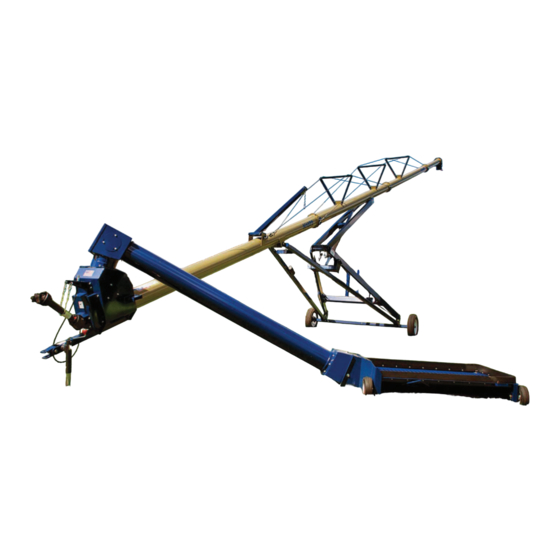
H1062, H1072, & H1082 AUGER ASSEMBLY MANUAL
Read & understand all instructions pertaining to this auger prior to use!
Previous
Page
Next
Page
1
2
3
4
5
Advertisement
Need help?
Do you have a question about the H1062 and is the answer not in the manual?
Ask a question
Questions and answers
Related Manuals for HARVEST H1062
Tools HARVEST H1384XT Operator's Manual
Grain auger (41 pages)
Tools HARVEST H1364XT Assembly Manual
(51 pages)
Tools HARVEST H1072 Assembly Manual
(60 pages)
Tools HARVEST H13104XT Operator's Manual
(45 pages)
Tools HARVEST H13102 Operator's Manual
Grain auger (47 pages)
Tools HARVEST H1084XT Operator's Manual
(43 pages)
Tools HARVEST T8 SERIES Assembly And Parts Manual
(91 pages)
This manual is also suitable for:
H1072
H1082
Print
Rename the bookmark
Delete bookmark?
Delete from my manuals?
Login
Sign In
OR
Sign in with Facebook
Sign in with Google
Upload manual
Upload from disk
Upload from URL


Need help?
Do you have a question about the H1062 and is the answer not in the manual?
Questions and answers