
Subscribe to Our Youtube Channel
Related Manuals for Festo CP-E16...M Series


Summary of Contents for Festo CP-E16...M Series
- Page 1 Compact performance Electronics manual CP modules Input module type CP−E16...−M...−... Input module type CP−E16−KL−IP20−Z Output module type CP−A08...−M12−... Manual 165 225 en 0802e [730 690]...
- Page 3 ....... . . 165 225 E (Festo AG & Co. KG, D 73726 Esslingen, Federal Republic of Germany, 2008) Internet: http://www.festo.com E−Mail:...
- Page 4 Contents and general instructions Festo P.BE−CPEA−EN en 0802e...
-
Page 5: Table Of Contents
........2−25 Festo P.BE−CPEA−EN en 0802e... - Page 6 ............A−1 Festo P.BE−CPEA−EN en 0802e...
-
Page 7: Designated Use
Extra−Low Voltage, PELV) for the electrical supply. Consider also the general requirements for PELV circuits in accordance with IEC/DIN EN 60204−1. S Use power supplies which guarantee reliable electrical isolation of the operating voltage as per IEC/DIN EN 60204−1. Festo P.BE−CPEA−EN en 0802e... -
Page 8: Target Group
Contents and general instructions Target group This manual is directed exclusively at technicians trained in control and automation technology. Service Please consult your local Festo repair service if you have any technical problems. Festo P.BE−CPEA−EN en 0802e... -
Page 9: Important User Instructions
This means that failure to observe this instruction may result in damage to property. The following pictogram marks passages in the text which describe activities with electrostatically sensitive compo nents. Electrostatically sensitive components may be damaged if they are not handled correctly. Festo P.BE−CPEA−EN en 0802e... - Page 10 Accessories: Information on necessary or sensible accessories for the Festo product. Environment: Information on environment−friendly use of Festo products. Text markings The bullet indicates activities which may be carried out in any order. 1. Figures denote activities which must be carried out in the numerical order specified.
-
Page 11: Notes On The Use Of This Manual
Output modules PNP: CP−A08−M12 CP−A08−M12−5POL NPN: CP−A08N−M12 Information on further modules, as well as basic information which must be observed in conjunction with the higher−order system, can be found in the manuals for the relevant systems. Festo P.BE−CPEA−EN en 0802e... - Page 12 Ó Ó Ó Ó Ó Ó Ó Ó Ó Ó Ó Ó Ó Ó Ó Ó Ô Ô Ô Ô Ô Ô Ô Ô Ô Ô Ô Ô Ô Fig. 0/1: Manuals on the CP system Festo P.BE−CPEA−EN en 0802e...
- Page 13 Description CPV valve terminal CP modules pneumatics electronics type P.BE−CPV−... type P.BE−CPEA−... Contents Information on the Information on the CPV valve terminals CP I/O modules Fig. 0/2: Manuals on the SPC200 Festo P.BE−CPEA−EN en 0802e...
- Page 14 Contents and general instructions Festo P.BE−CPEA−EN en 0802e...
-
Page 15: Input Modules Type Cp−E16
Input modules type CP−E16...−M...−... Chapter 1 1−1 Festo P.BE−CPEA−EN en 0802e... - Page 16 ......... . 1−33 1−2 Festo P.BE−CPEA−EN en 0802e...
-
Page 17: Function Of Input Modules Type Cp−E16...−M...−
16 sockets with M8 thread Provides 16 NPN inputs; CP−E16N−M8 sensor connections via 16 sockets with M8 thread CP−E16−M8−Z Provides 16 PNP or 16 NPN inputs and has its own connection for supplying the sen sor voltage 1−3 Festo P.BE−CPEA−EN en 0802e... -
Page 18: Display And Connecting Elements
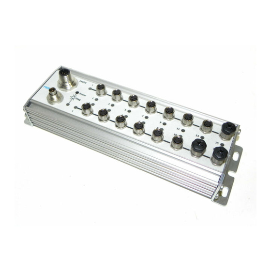
Identification for input type: INPUT−P for PNP inputs Earth/ground connection INPUT−N for NPN inputs Type plate Sensor connections Protective cap Yellow LED for status display CP connection (one LED per input) Fig. 1/1: Display and connecting elements 1−4 Festo P.BE−CPEA−EN en 0802e... - Page 19 CP−E16−M8−Z. Connection for the power supply to the sensors Red LED for displaying short circuits or failure of the sensor voltage (one LED per input group) Fig. 1/2: Additional elements of type CP−E16−M8−Z 1−5 Festo P.BE−CPEA−EN en 0802e...
-
Page 20: Input Modules Type Cp−E16
150 x 66 mm CP−E16−M8−Z approx. 217 x 66 mm CP−E16...−M12x2−... approx. 141 x 78 mm Fitting onto a wall The diagram below shows the dimensions for the four threaded holes of M4 screw size. 1−6 Festo P.BE−CPEA−EN en 0802e... - Page 21 1. Input modules type CP−E16...−M...−... 131.9 mm Input module, type CP−E16...−M12x2−... Input module, 63 mm type CP−E16...−M8 Input module, type CP−E16−M8−Z 40 mm 139.9 mm 40 mm 207.9 mm Fig. 1/3: Mounting dimensions for CP−E16...−M...−... 1−7 Festo P.BE−CPEA−EN en 0802e...
- Page 22 5. Fasten the housing to the fastening with the screws sup plied, as shown in the diagram below. 6. Tighten the screws. The fastening and the housing will then be clamped firmly on the hat rail. 1−8 Festo P.BE−CPEA−EN en 0802e...
- Page 23 Fig. 1/4: Fitting onto a hat rail Proceed with dismantling as follows: 1. Loosen the screws. 2. Remove the housing. 3. Lift the fastening out of the hat rail with a screwdriver. Screwdriver Fastening Fig. 1/5: Dismantling the fastening 1−9 Festo P.BE−CPEA−EN en 0802e...
-
Page 24: Installation
(see Fig. 1/1) with low impedance (short cable with large cross−sectional area) to the earth potential. In this way you can avoid faults due to electromagnetic influences and ensure electromagnetic compatibility in accordance with EMC guidelines. 1−10 Festo P.BE−CPEA−EN en 0802e... -
Page 25: Determining Pnp Or Npn Operation (Only With Type Cp−E16−M8−Z)
2: PNP/NPN 3. 0 V 4: not connected 5: earth/ground connection PNP operation (pins 2 and 3 bridged) NPN operation (pins 2 and 1 bridged) Fig. 1/6: Determining PNP or NPN operation (only with type CP−E16−M8−Z) 1−11 Festo P.BE−CPEA−EN en 0802e... -
Page 26: Connecting The Separate Power Supply For The Sensors (Only With Type Cp−E16−M8−Z)
(e.g. EMC). The connected sensors are supplied with + 24 V DC via the connection for the sensor supply. The module enables sen sors with high current consumption to be connected (max. 125 mA per sensor). 1−12 Festo P.BE−CPEA−EN en 0802e... - Page 27 2 3 1 4 5 ating voltage is supplied via the CP connection 24 V 230 V 24 V Fig. 1/7: Pin assignment and connection example of the sensor supply (PNP operation) 1−13 Festo P.BE−CPEA−EN en 0802e...
- Page 28 5 have the same potential and that there are no equalizing currents. In this way you can avoid faults due to electromagnetic influences and ensure electromagnetic compatibility in accordance with EMC guidelines. 1−14 Festo P.BE−CPEA−EN en 0802e...
-
Page 29: Connecting The Sensors
Fasten the plugs with the aid of the union nut in order to pre vent unintentional loosening, e.g. due to shock. Seal the un used sensor connections with the protective caps supplied. Only in this way can you comply with protection class IP 65. 1−15 Festo P.BE−CPEA−EN en 0802e... - Page 30 1: 24 V 2: Ex+1 3. 0 V 4: Ex + 2 Ex+2 Ex+3 1: 24 V Ex+1 2: Ex+1 3. 0 V 4: Ex Ex = Input x Fig. 1/9: Pin assignment of type CP−E16...−M12x2 1−16 Festo P.BE−CPEA−EN en 0802e...
- Page 31 3. 0 V 4: Ex+2 5: earth/ground Ex+2 Ex+3 connection Ex+1 1: 24 V 2: Ex+1 3. 0 V 4: Ex 5: earth/ground connection Ex = Input x Fig. 1/10: Pin assignment of type CP−E16−M12x2−5POL 1−17 Festo P.BE−CPEA−EN en 0802e...
- Page 32 Pin 3 Pin assignment PLC/IPC Ex (e.g. via field bus) 1: 24 V + 10/− 15 % Logic identifier Ex 4: Ex 3. 0 V Green LED Ex Ex = Input x Fig. 1/11: Internal structure 1−18 Festo P.BE−CPEA−EN en 0802e...
- Page 33 Circuitry examples of CP−E16−M8 (PNP inputs) and CP−E16−M8−Z with PNP operation Pin assignment 3. 24 V 4: Ex 3. 0 V Three−wire sensor (positive− switching) Two−wire sensor (positive− switching) Contact Ex = Input x Fig. 1/12: Circuitry examples 1−19 Festo P.BE−CPEA−EN en 0802e...
- Page 34 PLC/IPC Ex (e.g. via field bus) 4: Ex 5: Earth connection only with Logic identifier Ex type CP−E16−M12x2−5POL Green LED Ex PLC/IPC Ex+1 (e.g. via field bus) Ex = Input x Fig. 1/13: Internal structure 1−20 Festo P.BE−CPEA−EN en 0802e...
- Page 35 3. 0 V 4: Ex 5: *) Sensor 2 (Ex+1) positive switching 2−way distributor (T−piece) Sensor 1 (Ex) positive switching *) Only with type CP−16−M12x2−5POL earth/ground connection Ex = Input x Fig. 1/14: Circuitry examples 1−21 Festo P.BE−CPEA−EN en 0802e...
- Page 36 Pin 1 Pin assignment PLC/IPC Ex (e.g. via field bus) 1: 24 V + 10/− 15 % Logic identifier Ex 4: Ex 3. 0 V Green LED Ex Ex = Input x Fig. 1/15: Internal structure 1−22 Festo P.BE−CPEA−EN en 0802e...
- Page 37 Circuitry examples of CP−E16N−M8 (NPN inputs) and CP−E16−M8−Z with NPN operation Pin assignment 3. 24 V 4: Ex 3. 0 V Three−wire sensor (negative− switching) Two−wire sensor (negative− switching) Contact Ex = Input x Fig. 1/16: Circuitry examples 1−23 Festo P.BE−CPEA−EN en 0802e...
- Page 38 Green LED Ex+1 2: Ex+1 3. 0 V PLC/IPC Ex (via field bus) 4: Ex Logic identifier Ex PLC/IPC Ex+1 (e.g. via field bus) Green LED Ex Ex = Input x Fig. 1/17: Internal structure 1−24 Festo P.BE−CPEA−EN en 0802e...
- Page 39 1. Input modules type CP−E16...−M...−... Circuitry examples of CP−E16N−M12x2 (NPN inputs) Pin assignment Sensor 2 (Ex+1) (negative logic) 1. 24 V 2−way distributor (T−piece, e.g. Festo 2: Ex+1 Duo cable; only 4−pin) 3. 0 V 4: Ex Sensor 1 (Ex) (negative logic) Ex = Input x Fig.
-
Page 40: Connecting The Input Module
The following functions are provided for the module via the CP cable: Operating voltage for the internal electronics Connection for data exchange in the case of input modules without connection for sup plying the sensors: Operating voltage for the connected sensors. 1−26 Festo P.BE−CPEA−EN en 0802e... - Page 41 CP connection of the higher−order system (field bus node or axis interface or Powerbox) to the CP connection of a CP output module to the CP connection of a valve terminal. Further information can be found in the relevant system manual. 1−27 Festo P.BE−CPEA−EN en 0802e...
-
Page 42: Instructions On Commissioning
Proceed here as described in the manual for the SPC200 or in the WinPISA manual. Status LED The operating status of the input module is indicated by the status LED on the CP connection (see table below). 1−28 Festo P.BE−CPEA−EN en 0802e... - Page 43 SAVE button on the node (see Manual for the CP system, installation und commissioning"). With type CP−E16−M8−Z the short circuit LED on the relevant input group will light up. 1−29 Festo P.BE−CPEA−EN en 0802e...
- Page 44 The status LEDs of the relevant input group are switched off and the relevant inputs supply a 0−signal. The other input group remains ready to operate. When the short circuit is eliminated, the error will be deleted automatically. 1−30 Festo P.BE−CPEA−EN en 0802e...
- Page 45 If a fault occurs on a CP module during operation, you can replace the module during operation by another module of the same type. Please note Please note here the instructions in the manual for the higher−order system (e.g. CP system, CP field bus node, SPC200). 1−31 Festo P.BE−CPEA−EN en 0802e...
- Page 46 In this case, therefore, the status LEDs and the LEDs of the connected sensors will flash, providing there is a signal (logical 1). 1−32 Festo P.BE−CPEA−EN en 0802e...
-
Page 47: Technical Specifications
Immunity against interference Tested as per EN 50082−2 Vibration and shock Vibration Tested as per DIN/IEC 68/EN 60068 part 2−6; severity class 2 Shock Tested as per DIN/IEC 68/EN 60068 part 2−27; severity class 2 1−33 Festo P.BE−CPEA−EN en 0802e... - Page 48 Response delay (at 24 V) Typ. 3 ms 24 V ± 25 % Sensor supply V Max. 1 A per input group (electronic short−circuit protection per group) Electrical isolation None < 40 mA Internal current consumption of electronics 1−34 Festo P.BE−CPEA−EN en 0802e...
- Page 49 Response delay (at 24 V) Typ. 5 ms Typ. 3 ms 24 V ± 25 % Sensor supply V Max. 0.5 A (electronic short−circuit protection) Electrical isolation None < 40 mA Internal current consumption of Max. 90 mA electronics 1−35 Festo P.BE−CPEA−EN en 0802e...
- Page 50 8 mA Response delay (at 24 V) Typ. 5 ms 24 V ± 25 % Sensor supply V Max. 0.5 A (electronic short−circuit protection) Electrical isolation None Internal current consumption of electronics Max. 90 mA 1−36 Festo P.BE−CPEA−EN en 0802e...
- Page 51 Input module type CP−E16−KL−IP20−Z Chapter 2 2−1 Festo P.BE−CPEA−EN en 0802e...
- Page 52 ......... . 2−29 2−2 Festo P.BE−CPEA−EN en 0802e...
-
Page 53: Input Module Type Cp−E16−Kl−Ip20−Z
It has three 10−pin optional connecting sockets in screw or tension spring design and is therefore particularly suited for fitting into a control cabinet (IP20). 2−3 Festo P.BE−CPEA−EN en 0802e... -
Page 54: Display And Connecting Elements
(8 inputs per input module) Green LED for status display Connection for sensor power sup (one LED per input) Type plate Groove for identification signs (IBS 6x10) Status LED (green) Fig. 2/1: Display and connecting elements 2−4 Festo P.BE−CPEA−EN en 0802e... -
Page 55: Fitting
The diagram below shows the dimensions for the four threaded holes of M4 screw size. You should fasten the module with at least 3 screws. Input module, type CP−E16−KL−IP20−Z 166 mm Fig. 2/2: Mounting dimensions for CP−E16...−M...−... 2−5 Festo P.BE−CPEA−EN en 0802e... - Page 56 5. Fasten the housing to the fastening with the screws sup plied, as shown in the diagram below. 6. Tighten the screws. The fastening and the housing will then be clamped firmly on the hat rail. 2−6 Festo P.BE−CPEA−EN en 0802e...
- Page 57 Fig. 2/3: Fitting onto a hat rail Proceed with dismantling as follows: 1. Loosen the screws. 2. Remove the housing. 3. Lift the fastening out of the hat rail with a screwdriver. Screwdriver Fastening Fig. 2/4: Dismantling the fastening 2−7 Festo P.BE−CPEA−EN en 0802e...
-
Page 58: Installation
EMC guidelines. Caution Only connection X1 is used for the power supply to the sensors. Do not connect any external supply to terminals + and of X2 and X3. Otherwise the input module may be damaged. 2−8 Festo P.BE−CPEA−EN en 0802e... -
Page 59: Determining Pnp Or Npn Operation
A separate load supply for the valves/outputs can be looped through via pins 7 and 8. By means of the other internal bridges (24 V, FE, 0 V), the relevant potential can be passed on to the next CP module. 2−9 Festo P.BE−CPEA−EN en 0802e... -
Page 60: Connecting The Separate Power Supply For The Sensors
(e.g. EMC). The sensors are supplied with + 24 V DC via the connection for the sensor supply. The module enables sensors with high current consumption to be connected (max. 1 A per input module). 2−10 Festo P.BE−CPEA−EN en 0802e... - Page 61 1 2 3 4 5 6 7 8 9 10 *) Sensor supply for the inputs + 24 V DC ± 25 % P / N 0V Fig. 2/6: Pin assignment and connection example of the sensor supply (PNP operation) 2−11 Festo P.BE−CPEA−EN en 0802e...
- Page 62 5 or 6 have the same potential and that there are no equalizing currents. In this way you can avoid faults due to electromagnetic influences and ensure electromagnetic compatibility in accordance with EMC guidelines. 2−12 Festo P.BE−CPEA−EN en 0802e...
-
Page 63: Connecting The Sensors
Two rows of the three−row connector socket are intended as distributor boards for the sensor supply. These rows are each connected internally (see Fig. 2/9). Fasten these sockets with the aid of the fitted screws. The maximum tightening torque is 0.2 Nm. 2−13 Festo P.BE−CPEA−EN en 0802e... - Page 64 (e.g. a screwdriver) to press down the coloured push button assigned to the ten sion spring terminal. Tension spring socket from con nector set type SEA−KL−SAC10/30 Cables Screwdriver Fig. 2/7: Wiring the connector sockets 2−14 Festo P.BE−CPEA−EN en 0802e...
- Page 65 Further possible connector sets Connector connection cross section See leaflet X1, X2, X3 Type PSI ZC13−Z with product (tension spring sockets, 1−row) See leaflet X1, X2, X3 Type PSI ZC13−S with product (screw−terminal sockets, 1−row) 2−15 Festo P.BE−CPEA−EN en 0802e...
-
Page 66: Pin Assignment (Pnp And Npn Inputs)
Plug X3 +: 24 V DC 0: I8 1: I9 2: I10 3: I11 4: I12 5: I13 6: I14 7: I15 −: 0 V DC Fig. 2/8: Pin assignment of plugs X2 and X3 2−16 Festo P.BE−CPEA−EN en 0802e... -
Page 67: Circuitry Examples Of Pnp Inputs
(0 V) Pin assignment 24 V 0...7: Ix + n −: Contact Two−wire sensor (positive−switch ing) Three−wire sensor (positive−switch ing) Ix = Input x Fig. 2/9: PNP inputs (3−row connector socket set SEA−KL−SAC10/30) 2−17 Festo P.BE−CPEA−EN en 0802e... - Page 68 Pin assignment 24 V 0...7: Ix + n −: External potential distribution (0 V) Contact Two−wire sensor (positive−switch ing) Three−wire sensor (positive−switch ing) Ix = Input x Fig. 2/10: PNP inputs (1 row, connector socket) 2−18 Festo P.BE−CPEA−EN en 0802e...
- Page 69 PLC/IPC Ix (e.g. via field bus) 24 V ± 25 % Logic recognition Ix + n 0...7: Ix + n −: Green LED Ix + n Ix = Input x Fig. 2/11: Internal structure (PNP operation) 2−19 Festo P.BE−CPEA−EN en 0802e...
-
Page 70: Circuitry Examples Of Npn Inputs
(0 V) Pin assignment 24 V 0...7: Ix + n −: Contact Two−wire sensor (negative−switch ing) Three−wire sensor (negative−switch ing) Ix = Input x Fig. 2/12: NPN inputs (3−row connector socket set SEA−KL−SAC10/30) 2−20 Festo P.BE−CPEA−EN en 0802e... - Page 71 Ix + n −: External potential distribution (0 V) Three−wire sensor (negative−switch ing) Two−wire sensor (negative−switch ing) Contact External potential distribution (24 V) Ix = Input x Fig. 2/13: NPN inputs (1 row, connector socket) 2−21 Festo P.BE−CPEA−EN en 0802e...
-
Page 72: Pin Assignment (Pnp And Npn Inputs)
PLC/IPC Ix (e.g. via field bus) 24 V ± 25 % Logic recognition Ix + n 0...7: Ix + n − Green LED Ix + n Ix = Input x Fig. 2/14: Internal structure (NPN operation) 2−22 Festo P.BE−CPEA−EN en 0802e... -
Page 73: Connecting The Input Module
SPC−AIF−... SPC200 type P.BE−SPC200−... Powerbox type See manual for the CP−FB−TBOX−... higher−order system The following functions are provided for the module via the CP cable: Operating voltage for the internal electronics Connection for data exchange 2−23 Festo P.BE−CPEA−EN en 0802e... - Page 74 CP connection of the higher−order system (field bus node or axis interface or Powerbox) to the CP connection of a CP output module to the CP connection of a valve terminal. Further information can be found in the relevant system manual. 2−24 Festo P.BE−CPEA−EN en 0802e...
-
Page 75: Instructions On Commissioning
Proceed here as described in the manual for the SPC200 or in the WinPISA manual. Status LED The operating status of the input module is indicated by the status LED on the CP connection (see table below). 2−25 Festo P.BE−CPEA−EN en 0802e... - Page 76 When the string assignment has been modified (CP modules added or removed), the new string assignment must be saved or configured (see manual CP system, installation and com− missioning" or CP valve terminal with direct connection"). The short circuit LED of the relevant input module lights up. 2−26 Festo P.BE−CPEA−EN en 0802e...
- Page 77 However, the inputs are no longer processed in respect of software. For all 16 inputs, the mod ule supplies a 0−signal to the higher−order system. When the short circuit is eliminated, the error will be deleted auto matically. 2−27 Festo P.BE−CPEA−EN en 0802e...
- Page 78 There are green LEDs above the sensor connections. These indicate the status of the signal at the relevant input. The LEDs indicate the following: Status LED Sequence Status Logical 1 (signal present) LED lights up Logical 0 (no signal) LED is out 2−28 Festo P.BE−CPEA−EN en 0802e...
-
Page 79: Technical Specifications
Vibration and shock Vibration Tested as per DIN/IEC 68/EN 60068 part 2−6; Severity class 2 Shock Tested as per DIN/IEC 68/EN 60068 part 2−27; Severity class 2 1) The maximum permitted signal cable length is 30 m. 2−29 Festo P.BE−CPEA−EN en 0802e... - Page 80 Max. 1 A per input group (electronic short−circuit protection per group) Electrical isolation of the power supply for the sensors/inputs from the power supply for the electronics and the CP bus < 40 mA Internal current consumption of electronics 2−30 Festo P.BE−CPEA−EN en 0802e...
-
Page 81: Output Modules Type Cp−A08...−M12−
Output modules type CP−A08...−M12−... Chapter 3 3−1 Festo P.BE−CPEA−EN en 0802e... - Page 82 ......... . 3−20 3−2 Festo P.BE−CPEA−EN en 0802e...
-
Page 83: Summary
(one LED per output) Protective cap CP connection Groove for identification signs (IBS 6x10) Load voltage connection Earth/ground connection Identifier for output type OUTPUT−P for PNP outputs OUTPUT−N for NPN outputs Fig. 3/1: Display and connecting elements 3−3 Festo P.BE−CPEA−EN en 0802e... -
Page 84: Fitting
163.9 mm Fig. 3/2: Fitting dimensions for output module CP−A08...−M12−... Fitting onto a hat rail The procedure for fitting onto a hat rail is the same as with the input modules type CP−E16...−M... (see section 1.2). 3−4 Festo P.BE−CPEA−EN en 0802e... -
Page 85: Installation
(see fig. 2/1) with low impedance (short cable with large cross−sectional area) to the earth potential. In this way you can avoid faults due to electromagnetic influences and ensure electromagnetic compatibility in accordance with EMC guidelines. 3−5 Festo P.BE−CPEA−EN en 0802e... -
Page 86: Connecting The Actuators
3. 0 V 4: Ax+1 Ax+1 Pin assignment 1: n.c. 2: n.c. 3. 0 V 4: Ax n.c. = not connected (not connected) Ax = Output x Fig. 3/3: Pin assignment of output module CP−A08...−M12−... 3−6 Festo P.BE−CPEA−EN en 0802e... - Page 87 Pin assignment 1: n.c. 2: Ax+1 3. 0 V 4: Ax 5: earth/ground connection n.c.= not connected (not connected) Ax = Output x Fig. 3/4: Pin assignment of output module CP−A08−M12−5POL 3−7 Festo P.BE−CPEA−EN en 0802e...
- Page 88 0, 2, 4, 6: Ax+1 load voltage failure connections 1, 3, 5, 7: PLC/IPC Ax (e.g. via field bus) n.c. = not connected Electrical isolation Yellow LED Fig. 3/5: Internal structure of output module CP−A08...−M12−... 3−8 Festo P.BE−CPEA−EN en 0802e...
- Page 89 *) On type CP−A08...−M12−... n.c. = not connected on type CP−A08−M12−5POL connections 0, 2, 4, 6: Ax+1 connections 1, 3, 5, 7: n.c. = not connected Fig. 3/6: Examples of circuitry for output module CP−A08...−M12−... 3−9 Festo P.BE−CPEA−EN en 0802e...
- Page 90 1: 24 V 2: earth/ground connection 3: n.c. 4: Ax Current consumer/load must be supplied via this 24 V connection n.c.= not connected Ax = output x Fig. 3/7: Pin assignment of output module CP−A08N−M12−... 3−10 Festo P.BE−CPEA−EN en 0802e...
- Page 91 Load voltage connection Diagnosis short circuit/overload Actuator connection load voltage failure n.c. = not connected PLC/IPC Ax (e.g. via field bus) Yellow LED Electrical isolation Green LED Fig. 3/8: Internal structure of output module CP−A08N−M12 3−11 Festo P.BE−CPEA−EN en 0802e...
- Page 92 2: earth/ground connection 3: n.c. not permitted 4: Ax+1 n.c.= not connected Current consumer/load must be Ax = Output x supplied via this 24 V connection Fig. 3/9: Examples of circuitry of output module CP−A08N−M12 3−12 Festo P.BE−CPEA−EN en 0802e...
-
Page 93: Connecting The Output Module
CP cable. The output module is connected directly to the CP connection of the higher−order system (field bus node, axis interface or Powerbox). Detailed information can be found in the relevant system manual. 3−13 Festo P.BE−CPEA−EN en 0802e... -
Page 94: Connecting The Load Voltage
(e.g. EMC). The connected actuators are supplied with + 24 V DC via the load voltage connection on the output module. Use a cable for the operating voltage with sufficient cross−sectional area. 3−14 Festo P.BE−CPEA−EN en 0802e... - Page 95 1 3 2 4 plied via the CP connection. n.c. = not connected (not connected) 24 V 230 V 24 V Fig. 3/10: Pin assignment and example of the load voltage connection 3−15 Festo P.BE−CPEA−EN en 0802e...
- Page 96 EMERGENCY STOP (e.g. switching of the operating voltage for the valves and output modules, switching off the com pressed air). 3−16 Festo P.BE−CPEA−EN en 0802e...
-
Page 97: Instructions On Commissioning
Proceed here as described in the manual for the SPC200 or in the WinPISA manual. Status LED The operating status of the output module is indicated by the status LED on the CP connection (see table below). 3−17 Festo P.BE−CPEA−EN en 0802e... - Page 98 The fault must be eliminated when the outputs are reset. (e.g. by user program). When the string assignment has been modified (CP modules added or removed), you must save the new string assignment by pressing the SAVE button on the node. 3−18 Festo P.BE−CPEA−EN en 0802e...
- Page 99 These indicate the status of the signal at the rel evant output. The meanings are as follows: Status LED Sequence Status Output supplies a 1−signal LED lights up Output supplies a 0−signal LED is out 3−19 Festo P.BE−CPEA−EN en 0802e...
-
Page 100: Technical Specifications
Electrically isolated load voltage supply via additional M18 plug connector Rated value 24 V (protected against incorrect polarity) ± 25 % Tolerance Residual ripple 4 Vpp (within tolerance) Insulation resistance 500 V < 40 mA Internal current consumption of electronics 3−20 Festo P.BE−CPEA−EN en 0802e... - Page 101 Digital outputs Design 8 outputs as per IEC 1131−2; 24 V DC, negative−switching Maximum load per digital output 0.5 A Electronic fuse (short circuit, overload) Trigger current Typical 1 A Response time Max. 1.5 ms 3−21 Festo P.BE−CPEA−EN en 0802e...
- Page 102 3. Output modules type CP−A08...−M12−... 3−22 Festo P.BE−CPEA−EN en 0802e...
- Page 103 Index Appendix A A−1 Festo P.BE−CPEA−EN en 0802e...
-
Page 104: A. Index
............A−3 A−2 Festo P.BE−CPEA−EN en 0802e... - Page 105 ......Input module Circuitry example CP−E16−M8 (NPN) ....2−20 A−3 Festo P.BE−CPEA−EN en 0802e...
- Page 106 ........VIII A−4 Festo P.BE−CPEA−EN en 0802e...
- Page 107 ........Technical specifications Input module CP−E16...−... (general specifications) 2−29 A−5 Festo P.BE−CPEA−EN en 0802e...
- Page 108 ........VIII A−6 Festo P.BE−CPEA−EN en 0802e...
Need help?
Do you have a question about the CP-E16...M Series and is the answer not in the manual?
Questions and answers