
Related Manuals for Festo CPX-AP-I-4AI-U-I-RTD-M12


Summary of Contents for Festo CPX-AP-I-4AI-U-I-RTD-M12
- Page 1 CPX-AP-I-4AI-U-I-RTD-M12 Analogue input module Instructions | Operat- 8099769 8099769 2020-03 [8099771]...
- Page 2 Translation of the original instructions Festo — CPX-AP-I-4AI-U-I-RTD-M12 — 2020-03...
-
Page 3: Table Of Contents
Scaling for compatibility with other CPX analogue modules........17 Hysteresis for measured value monitoring..............18 Assembly........................19 Installation........................19 Commissioning......................19 Parameterisation......................19 Diagnostics and fault clearance.................. 21 11.1 Diagnostic messages....................21 11.2 LED displays......................... 24 Disposal........................25 Technical data......................26 Festo — CPX-AP-I-4AI-U-I-RTD-M12 — 2020-03... -
Page 4: About This Document
The product labelling is located on the right-hand side of the module. The Data Matrix code is on the connection side. Scanning the printed Data Matrix Code with an appropriate device opens the Festo Support Portal with the information appropriate for the product. Alternatively, the Product Key (11-digit alphanumeric code on the product labelling) can be entered in the search field of the Support Portal è www.festo.com/sp. -
Page 5: Safety
Installation, commissioning, maintenance and disassembly should only be conducted by qualified per- sonnel. The qualified personnel must be familiar with installation of electrical control systems. Additional information – Accessories è www.festo.com/catalogue. Service Contact your regional Festo contact person if you have technical questions è www.festo.com. Festo — CPX-AP-I-4AI-U-I-RTD-M12 — 2020-03... -
Page 6: Product Overview
To do this, the sensor supply is switched on briefly and switched off again in the event of an error. The electronic fuse of the module is a slow-blow type. Sensors can therefore also be connected with a temporarily higher current requirement. Festo — CPX-AP-I-4AI-U-I-RTD-M12 — 2020-03... -
Page 7: Configuration
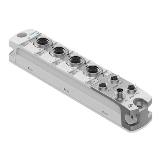
10 Mounting interface connection side bottom and connection functional earth FE 11 Mounting interface, lateral bottom and connection for functional earth FE 12 Inscription label (optional) 13 Mounting interface, lateral top Fig. 1 Product design Festo — CPX-AP-I-4AI-U-I-RTD-M12 — 2020-03... -
Page 8: Led Displays
5.2.3 Connecting elements Connection for power supply [XD1] Plug M8, 4-pin, A-coded Signal +24 V DC logic supply PS 0 V DC load supply PL 0 V DC logic supply PS +24 V DC load supply PL Tab. 4 Connection for power supply Festo — CPX-AP-I-4AI-U-I-RTD-M12 — 2020-03... - Page 9 +24 V DC sensor supply Positive constant current Measuring input + Measuring input + 0 V DC sensor supply Constant current mass Measuring input Measuring input – – Functional earth FE Functional earth FE Tab. 8 Connection for inputs Festo — CPX-AP-I-4AI-U-I-RTD-M12 — 2020-03...
-
Page 10: Connection Example For Voltage Measurement
3 Connection between pin 3 and pin 4 4 Measuring resistor Fig. 4 Connection example, current measurement, 2-wire connection 3-wire connection In this connection example, it is necessary to connect pin 3 and pin 4 together. Festo — CPX-AP-I-4AI-U-I-RTD-M12 — 2020-03... -
Page 11: Connection Examples For Temperature And Resistance Measurement
Fig. 6 Connection example for current measurement, 4-wire connection 5.2.3.3 Connection examples for temperature and resistance measurement 2-wire connection In this connection example, it is necessary to connect pin 1 and pin 2 as well as pin 3 and pin 4 togeth- Festo — CPX-AP-I-4AI-U-I-RTD-M12 — 2020-03... - Page 12 4 Constant current source in the module Fig. 8 Connection example, resistance measurement, 3-wire connection 4-wire connection 1 Module connecting pins 2 Resistance or temperature sensor 3 Constant current source in the module Fig. 9 Connection example, resistance measurement, 4-wire connection Festo — CPX-AP-I-4AI-U-I-RTD-M12 — 2020-03...
-
Page 13: Analogue Value Display
… – … < 5.1 V 32640 0x807F Underflow – – < < < 1) 1 LSB (least significant bit) corresponds to 156 μV; resolution 16 bits Tab. 11 Voltage measuring range –5 V... +5 V Festo — CPX-AP-I-4AI-U-I-RTD-M12 — 2020-03... -
Page 14: Unipolar Signal Ranges
– … – … < 0.2 mA 0xFFFE Underflow – – < < < 1) 1 LSB (least significant bit) corresponds to 781 nA; resolution 16 bits Tab. 14 Current measuring range 0 mA... 20 mA Festo — CPX-AP-I-4AI-U-I-RTD-M12 — 2020-03... -
Page 15: Resistance Measurement
200 °C 210 °C 2001 2100 0xF82E 0xF7CB Underdrive range – … – – … – … < 210 °C 2100 0xF7CB Underflow – – < < < Tab. 17 Temperature measurement PT100 Festo — CPX-AP-I-4AI-U-I-RTD-M12 — 2020-03... -
Page 16: Linear Scaling
10000 (upper limit) 7.5 V 7500 7.5 V 8000 5.0 V 5000 5.0 V 6000 2.5 V 2500 2.5 V 4000 0 (lower limit) 2000 (lower limit) Tab. 19 Examples: Signal range 0 V... 10 V (linear scaling active) Festo — CPX-AP-I-4AI-U-I-RTD-M12 — 2020-03... -
Page 17: Scaling For Compatibility With Other Cpx Analogue Modules
– Upper limit: 27648 Bipolar signal ranges: – Lower limit: –27648 – Upper limit: 27648 As a result, a new module behaves like an earlier module and no changes to the controller are neces- sary. Festo — CPX-AP-I-4AI-U-I-RTD-M12 — 2020-03... -
Page 18: Hysteresis For Measured Value Monitoring
Resistance measurement: A hysteresis value Z0.1 Ω, i.e. a value of 100 means 10 Ωhysteresis. 1 Hysteresis value 4 Diagnostics off 2 Lower limit 5 Diagnostics on 3 Upper limit Fig. 10 Hysteresis for measured value monitoring Festo — CPX-AP-I-4AI-U-I-RTD-M12 — 2020-03... -
Page 19: Assembly
è Instruction manual for automation system CPX-AP è 11 Diagnostics and fault clearance Parameterisation Various parameters are available for reading out information about the modules in an automation sys- tem CPX-AP and adapting the modules to the application situation. Festo — CPX-AP-I-4AI-U-I-RTD-M12 — 2020-03... - Page 20 – 7: 128 values (2 – 8: 256 values (2 – 9: 512 values (2 – 10: 1024 values (2 – 11: 2048 values (2 – 12: 4096 values (2 – 13: 8192 values (2 Festo — CPX-AP-I-4AI-U-I-RTD-M12 — 2020-03...
-
Page 21: Diagnostics And Fault Clearance
Short circuit/overload The connected sensor is defective or generates too much (16843019) in sensor supply load on its channel. Remedy – Check sensor for correct function, in par- ticular for current consumption. – Check sensor cabling. Festo — CPX-AP-I-4AI-U-I-RTD-M12 — 2020-03... - Page 22 – Check parameters. shot – Check sensor. Diagnost- Error ic status 06 05 0062 Parameter set invalid Parameter set invalid. (100991074) Remedy – Delete parameter set. – Overwrite parameter set (save). Diagnost- Error ic status Festo — CPX-AP-I-4AI-U-I-RTD-M12 — 2020-03...
- Page 23 A wire break has been detected for the channel (only avail- (134218037) able for the signal ranges 1 V 5 V and 4 mA 20 mA). … … Remedy – Check wiring. Diagnost- Error ic status Tab. 23 Diagnostic messages Festo — CPX-AP-I-4AI-U-I-RTD-M12 — 2020-03...
-
Page 24: Led Displays
PL Illuminated red – Module ramp-up not yet completed. System communication not yet initial- ised. LED flashes red quickly – Module identification (service function) Flashes quickly green Tab. 24 LED module diagnostics [MD] Festo — CPX-AP-I-4AI-U-I-RTD-M12 — 2020-03... -
Page 25: Disposal
Check connected sensors or parameter setting. flashes – No diagnostics at the input Tab. 25 LED diagnostics input Disposal ENVIRONMENT! Send the packaging and product for environmentally sound recycling in accordance with the current regulations è www.festo.com/sp. Festo — CPX-AP-I-4AI-U-I-RTD-M12 — 2020-03... -
Page 26: Technical Data
SELV/PELV circuits tric shock (protection (safe extra-low voltage/protected extra-low voltage) against direct and indirect contact in accordance with IEC 60204-1) Electromagnetic com- see declaration of conformity www.festo.com è patibility Mounting position Tab. 26 General technical data Festo — CPX-AP-I-4AI-U-I-RTD-M12 — 2020-03... - Page 27 Logic supply PS [V DC] 24 25 % Intrinsic current con- [mA] Typ. 38 sumption at nominal operating voltage 24 V from PS Sensor current per 1.0 (max.) module Sensor current per 0.5 (max.) channel Tab. 27 Power supply Festo — CPX-AP-I-4AI-U-I-RTD-M12 — 2020-03...
- Page 28 Error limits (based on full scale) Temperature fault [%/K] 0.01 Linearity error [%/K] 0.01 (at 25 °C) Repetition accuracy 0.025 (at 25 °C) Usage error limit (T T … Voltage measurement 0.15 Current measurement 0.15 Resistance measure- 0.35 ment Festo — CPX-AP-I-4AI-U-I-RTD-M12 — 2020-03...
- Page 29 24 V PS against 0 V PS Protection against [V DC] max. PL reverse voltage Sensor power supply short circuit protection Short-circuit protection Electronic Trigger level 0.7 Characteristic Slow-blowing Behaviour after end of Automatic return overload Tab. 28 Analogue inputs Festo — CPX-AP-I-4AI-U-I-RTD-M12 — 2020-03...
- Page 30 Copyright: Festo SE & Co. KG Ruiter Straße 82 73734 Esslingen Germany Phone: +49 711 347-0 Internet: www.festo.com © 2020 all rights reserved to Festo SE & Co. KG...
Need help?
Do you have a question about the CPX-AP-I-4AI-U-I-RTD-M12 and is the answer not in the manual?
Questions and answers