Festo CPX-E-4IOL Manual
Io-link master module
Hide thumbs
Also See for CPX-E-4IOL:
- Instructions for use (3 pages) ,
- Translation of the original instructions (30 pages) ,
- Operating instructions (4 pages)

Related Manuals for Festo CPX-E-4IOL


Summary of Contents for Festo CPX-E-4IOL
- Page 1 System CPX-E IO-Link master module CPX-E-4IOL-… Description Protocol IO-Link Function Parameterisation 8071107 2017-07 [8071109]...
- Page 2 CPX-E-4IOL-… Original instructions CPX-E-4IOL-…-E N ® IO-Link is a registered trademark of its respective trademark holder in certain countries. Symbols used: Note Material damage or loss of function Recommendations, tips, references to other documentation Festo – CPX-E-4IOL-…-EN – 2017-07 –...
-
Page 3: Table Of Contents
..................Festo – CPX-E-4IOL-…-EN – 2017-07 – English... -
Page 4: About This Document
1) Use in an industrial environment and process automation according to NE 21 Tab. 1.2 The product version can be identified from the product label or with the help of appropriate software from Festo. Appropriate software for identifying the product version can be found in the Festo Support Portal è... -
Page 5: Product Label
The product label is located on the left-hand side of the module. Scanning the printed Data Matrix Code with an appropriate device calls up the Festo Support Portal, with information appropriate for the product. Alternatively, the product key (11-digit alphanumeric code or product label) can be entered in the search field of the Support Portal. -
Page 6: Function
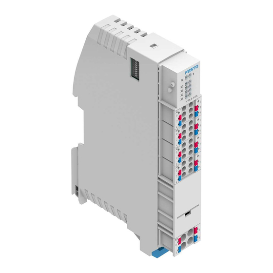
The address space provided to the IO-Link interfaces (ports) by the module is defined by DIL switches. Detailed information on the DIL switches can be found in the Detailed information on the DIL switches can be found in the “Instructions for use of CPX-E-4IOL-…” è 1.1 Further applicable documents. 2.1.1 Product design 1 LED displays 2 Terminal strips of the IO-Link interface (Ports 1 …... -
Page 7: Control Elements
+24 V DC load voltage supply U 0 V DC load voltage supply U 1) The connections XD.0 and XD.1 and also XD.2 and XD.3 are interconnected in the terminal strip. Tab. 2.3 Festo – CPX-E-4IOL-…-EN – 2017-07 – English... -
Page 8: Functional Example
The module described in this document has IO-Link interfaces (ports) of Class B (Type B) that provides an additional load voltage supply. The devices description by IODD (IO Device Description) is not supported. Festo – CPX-E-4IOL-…-EN – 2017-07 – English... -
Page 9: Diagnostics
No IO-Link communication exists – Tab. 2.5 Standard IO mode (SIO) [X0] … [X3] LED (yellow) Meaning Remedy Process signal = 1 – Lights up Process signal = 0 – Tab. 2.6 Festo – CPX-E-4IOL-…-EN – 2017-07 – English... -
Page 10: Diagnostic And Error Messages
The prioritisation of the individual modules in system CPX-E runs to the right in descending order from the bus module (position always a the far left). – Diagnostic/error messages from inputs have priority over diagnostic/error messages from outputs. Festo – CPX-E-4IOL-…-EN – 2017-07 – English... -
Page 11: Diagnostic/Error Messages According To Error Numbers
When accessing the module through the software, the respectively current error can be determined more precisely for each port using an event code insofar are the error is returned to the connected device è 2.3.4 Event codes. Festo – CPX-E-4IOL-…-EN – 2017-07 – English... -
Page 12: Event Codes
Maintenance required – refill 0x8C42 Maintenance required – replace wearing parts 1) Representation of MSB left, LSB right 2) L+, P24 3) Only relevant if the PL monitoring is active in a device. Tab. 2.10 Festo – CPX-E-4IOL-…-EN – 2017-07 – English... -
Page 13: Parameterisation
Device error code (high) + 35 1) Function number (è Description of system CPX-E); m = module number (counted from left to right, starting with 0) 2) Only read access possible Tab. 3.1 Festo – CPX-E-4IOL-…-EN – 2017-07 – English... -
Page 14: Parameter
Leave load voltage deactivated Leave deactivated Reactivate load voltage Reactivate automatically (preset) 1) Function number (è Description of system CPX-E); m = module number (counted from left to right, starting with 0) Tab. 3.4 Festo – CPX-E-4IOL-…-EN – 2017-07 – English... -
Page 15: Ps Supply
1) Function number (è Description of system CPX-E); m = module number (counted from left to right, starting with 0) 2) In case of a setting of 0, the minimum supported cycle time of the IO-Link® device is used. Tab. 3.6 Festo – CPX-E-4IOL-…-EN – 2017-07 – English... -
Page 16: Pl Supply (Port 1
Deactivate load voltage Inactive Switch on the load voltage Active (default) 1) Function number (è Description of system CPX-E); m = module number (counted from left to right, starting with 0) Tab. 3.7 Festo – CPX-E-4IOL-…-EN – 2017-07 – English... -
Page 17: Operating Mode (Port 1
1) Function number (è Description of system CPX-E); m = module number (counted from left to right, starting with 0) 2) The parameter setting leads to a parameter error (error number 29) and the parameter setting of the port switches to “Inactive.” Tab. 3.8 Festo – CPX-E-4IOL-…-EN – 2017-07 – English... -
Page 18: Linestate (Port 1
2) Function number (è Description of system CPX-E); m = module number (counted from left to right, starting with 0) 3) IO-Link communication set up 4) IO-Link communication set up, process data transferred Tab. 3.9 Festo – CPX-E-4IOL-…-EN – 2017-07 – English... -
Page 19: Device Error Code (Port 1
16 Bit (hexadecimal) + 34 High + 35 1) Only read access possible 2) Function number (è Description of system CPX-E); m = module number (counted from left to right, starting with 0) Tab. 3.10 Festo – CPX-E-4IOL-…-EN – 2017-07 – English... -
Page 20: A Technical Data
(Protected Extra-Low Voltage) Electromagnetic compatibility To EN 61000-6-2/-4 To EN 61000-6-2/-4 and NE 21 1) Including linking 2) With horizontal mounting position 3) Depending on the setting of the DIL switches Tab. A.1 Festo – CPX-E-4IOL-…-EN – 2017-07 – English... - Page 21 Yes, for system and load voltage supply respectively 1) According to IO-Link specification V1.1 2) The cycle time used can be permanently set using the “Cycle time” parameter (è Tab. 3.6). 3) Without feedback protection Tab. A.3 Festo – CPX-E-4IOL-…-EN – 2017-07 – English...
-
Page 22: B Terminology
Collective term for modules that provide analogue or digital inputs and/or outputs. Modules CPX-E Collective term for modules that can be integrated in system CPX-E. System CPX-E Complete system consisting of modules CPX-E. Tab. B.1 Festo – CPX-E-4IOL-…-EN – 2017-07 – English... -
Page 23: Index
– IO-Link mode (IOL), 9 – Load voltage supply, 10 – Module error, 9 Target group, 4 – Standard IO mode (SIO), 9 Technical data, 20 LineState, 18 Terminology, 22 Load voltage supply, 10 Festo – CPX-E-4IOL-…-EN – 2017-07 – English... - Page 24 Copyright: Festo AG & Co. KG Ruiter Straße 82 73734 Esslingen Germany Phone: +49 711 347-0 Fax: +49 711 347-2144 e-mail: Reproduction, distribution or sale of this document or communication of service_international@festo.com its contents to others without express authorization is prohibited. Offend...
Need help?
Do you have a question about the CPX-E-4IOL and is the answer not in the manual?
Questions and answers