
Related Manuals for Festo CP-E08-M12-CL


Summary of Contents for Festo CP-E08-M12-CL
- Page 1 Compact performance Electronics manual CP modules Input modules type CP−E08−M12−CL type CP−E08−M8−CL type CP−E16−KL−CL Output module type CP−A04−M12−CL Manual 539 300 en 0404NH [681 792]...
- Page 3 ....... . . 539 300 E (Festo AG & Co. KG, D 73726 Esslingen, Federal Republic of Germany, 2004) Internet: http://www.festo.com...
- Page 4 Contents and general instructions Festo P.BE−CPEA−CL−EN en 0404NH...
-
Page 5: Table Of Contents
....... . . 3−7 3.3.2 Connect the output module to the CP string ....3−8 Festo P.BE−CPEA−CL−EN en 0404NH... - Page 6 ............B−3 Festo P.BE−CPEA−CL−EN en 0404NH...
-
Page 7: Designated Use
IEC 742/EN 60742/VDE 0551 with at least 4 kV isolation resistance (Protected Extra Low Voltage PELV). Switch power packs are permitted, providing they guarantee reliable isolation in accordance with EN 60950/ VDE 0805. Festo P.BE−CPEA−CL−EN en 0404NH... -
Page 8: Target Group
Contents and general instructions Target group This manual is directed exclusively at technicians trained in control and automation technology. Service Please consult your local Festo repair service if you have any technical problems. Festo P.BE−CPEA−CL−EN en 0404NH... -
Page 9: Important User Instructions
This means that failure to observe this instruction may result in damage to property. The following pictogram marks passages in the text which describe activities with electrostatically sensitive compo nents. Electrostatically sensitive components may be damaged if they are not handled correctly. Festo P.BE−CPEA−CL−EN en 0404NH... - Page 10 Accessories: Information on necessary or sensible accessories for the Festo product. Environment: Information on environment−friendly use of Festo products. Text markings The bullet indicates activities which may be carried out in · any order. 1. Figures denote activities which must be carried out in the numerical order specified.
-
Page 11: Notes On The Use Of This Manual
(see sec tion A.5.4). Information on further CP modules as well as basic informa tion, which must be observed in conjunction with the CP master, can be found in the manuals for the relevant module. Festo P.BE−CPEA−CL−EN en 0404NH... - Page 12 CPV valve terminals (type 10). Pneumatics type P.BE−CPV−... manual manual Valve terminals with CPV Information on fitting, installing and pneumatics" commissioning CPA valve terminals (type 12). type P.BE−CPA−... Tab. 0/2: Manuals on the CP system Festo P.BE−CPEA−CL−EN en 0404NH...
- Page 13 Node CP field bus node with/without field bus connection, to which the I/O modules are connected. Digital output O module CP output module PLC/IPC Programmable logic controller/industrial PC Tab. 0/3: Terms and abbreviations Festo P.BE−CPEA−CL−EN en 0404NH...
- Page 14 Contents and general instructions Festo P.BE−CPEA−CL−EN en 0404NH...
-
Page 15: System Summary Cp System
System summary CP system Chapter 1 1−1 Festo P.BE−CPEA−CL−EN en 0404NH... - Page 16 Basic rules for addressing ....... . 1−13 1−2 Festo P.BE−CPEA−CL−EN en 0404NH...
-
Page 17: Setting Up Cp Systems
1. System summary CP system Setting up CP systems Festo can assist you in solving your automation task at the machine level with the aid of valve terminals. Due to their modular structure, the CP valve terminals from Festo will enable you to include valve terminals and I/O modules optimally in your machines and systems. - Page 18 System losses can be minimized if short compressed air tub ing is used and the times required for pressurizing and ex hausting the tubing can be reduced. This enables smaller valves with sufficient flow to be used, thereby helping to reduce costs. 1−4 Festo P.BE−CPEA−CL−EN en 0404NH...
-
Page 19: Method Of Operation Of The Cp System
These provide inputs for connecting sensors and enable e.g. cylinder positions to be scanned. Output modules These provide universal electric outputs for controlling low−current consuming devices (further valves, bulbs etc.). Tab. 1/1: Overview of CP modules 1−5 Festo P.BE−CPEA−CL−EN en 0404NH... - Page 20 Field bus (incoming) Field bus (continuing) CP valve terminal CP input module Sensor Cylinder CP output module CP master (here CP field bus node) Fig. 1/2: Method of operation of the CP system 1−6 Festo P.BE−CPEA−CL−EN en 0404NH...
-
Page 21: Variants Of The Cp System
CP modules with extended functions are distinguished by the following features: incoming and continuing CP interface any desired sequence of the modules within the CP string maximum 4 modules are possible per CP string. 1−7 Festo P.BE−CPEA−CL−EN en 0404NH... - Page 22 CP input module Fig. 1/3: Setting up a CP system (without extended functions), example In accordance with these rules, all CP modules with extended functions can also be connected to CP masters without ex tended functions. 1−8 Festo P.BE−CPEA−CL−EN en 0404NH...
- Page 23 Please note Irrespective of the type of CP modules (with or without extended functions), not more than 32 inputs and 32 out puts may be connected (sum of all 4 CP modules on a CP string). 1−9 Festo P.BE−CPEA−CL−EN en 0404NH...
- Page 24 16 I CP−E16−KL−IP20−Z 16 I 16 I CP−E16−KL−CL 16 I 16 I CP output modules CP−A08−M12−5POL 16 O 16 O CP−A08N−M12 16 O 16 O CP−A04−M12−CL 16 O Tab. 1/2: Assigned I/Os of the CP modules 1−10 Festo P.BE−CPEA−CL−EN en 0404NH...
-
Page 25: Use Of The I/O Modules
16 I + 16 O CPA−SC−DN 16 I + 16 O CDVI−DN 16 I + 16 O Support of the extended function in preparation, see manual for the relevant module Tab. 1/3: Overview of CP masters 1−11 Festo P.BE−CPEA−CL−EN en 0404NH... - Page 26 CP modules per string. The limitations de scribed in section 1.1.2 apply. Please note CP I/O modules with extended functions, e.g. type CP−...−CL, can also be operated on CP masters without extended functions (see Tab. 1/2). 1−12 Festo P.BE−CPEA−CL−EN en 0404NH...
-
Page 27: Basic Rules For Addressing
16 inputs or 16 outputs Depending on the type, modules with extended func tions occupy 8 or 16 inputs or 8 outputs Please note Further information on addressing can be found in the relevant manuals for the CP masters. 1−13 Festo P.BE−CPEA−CL−EN en 0404NH... - Page 28 1. System summary CP system 1−14 Festo P.BE−CPEA−CL−EN en 0404NH...
-
Page 29: Input Modules Type Cp−E08−M...−Cl And Cp−E16−Kl−Cl
Input modules type CP−E08−M...−CL and CP−E16−KL−CL Chapter 2 2−1 Festo P.BE−CPEA−CL−EN en 0404NH... -
Page 30: Input Modules Type Cp−E08−M
Diagnosis via the field bus ....... . 2−17 2−2 Festo P.BE−CPEA−CL−EN en 0404NH... -
Page 31: Function Of The Input Modules Cp−E08−M
Sensor connections via 2 series plugs, 10−pin and connector sockets in either screw or tension spring design. CP−E16−KL−CL Provides 16 PNP inputs. Especially suitable for fitting into a control cabinet (IP20). Tab. 2/1: Overview of input modules 2−3 Festo P.BE−CPEA−CL−EN en 0404NH... -
Page 32: Display And Connecting Elements
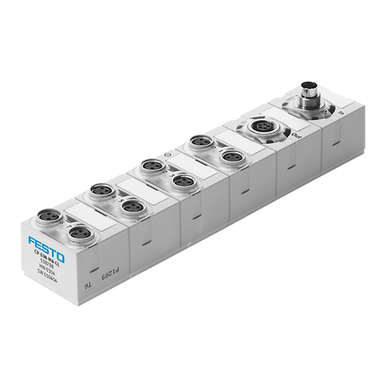
Sensor connections (2 inputs per socket) Fastening hole Type plate 6 grooves for identification signs (type IBS−8x20) Status LED CP communication (PS, green) Fastening hole with earth connection Fig. 2/1: Display and connecting elements type CP−E08−M12−CL 2−4 Festo P.BE−CPEA−CL−EN en 0404NH... - Page 33 Sensor connections (1 input per socket) Fastening hole Type plate 6 grooves for identification signs (type IBS−8x20) Status LED CP communication (PS, green) Fastening hole with earth connection Fig. 2/2: Display and connecting elements type CP−E08−M8−CL 2−5 Festo P.BE−CPEA−CL−EN en 0404NH...
- Page 34 Sensor connections (8 inputs per plug) Type plate Fastening hole 4 grooves for identification signs (type IBS−8x20) Status LED CP communication (PS, green) Fastening hole with earth connection Fig. 2/3: Display and connecting elements type CP−E16−KL−CL 2−6 Festo P.BE−CPEA−CL−EN en 0404NH...
-
Page 35: Fitting
75 + 0,5mm Input module type CP−E08−M8−CL Input module type CP−E16−KL−CL 141 + 0,5mm Fig. 2/4: Fitting dimensions CP−E...−CL Tip: The position of the fastening screws on clipped−in type plates is marked with the symbol 2−7 Festo P.BE−CPEA−CL−EN en 0404NH... -
Page 36: Installation
Connect the earthing cable on the housing (screw under type plate, see Fig. 2/1, Fig. 2/2 or Fig. 2/3) at low impe dance (short cable with large diameter) to the earth poten tial. A suitable cable clip is supplied with the module. 2−8 Festo P.BE−CPEA−CL−EN en 0404NH... -
Page 37: Connecting Sensors
Long signal cables reduce the immunity to interference. Make sure that the maximum permitted signal cable length of 30 m is not exceeded. Use plugs and cables from the Festo range (see Appendix A.5) for connecting sensors. In the case of CP input modules type CP−E08−M12−CL and CP−E08−M8−CL:... - Page 38 Ix = Input x Fig. 2/5: Pin assignment type CP−E08−M12−CL Pin assignment 1: 24 V 4: Ix+1 3: 0 V 1: 24 V 4: Ix+0 3: 0 V Ix = Input x Fig. 2/6: Pin assignment type CP−E08−M8−CL 2−10 Festo P.BE−CPEA−CL−EN en 0404NH...
- Page 39 +: 24 V DC Ix = Input x Fig. 2/7: Pin assignment of plugs X1 and X2 on type CP−E16−KL−CL Use spring tension plugs or screw connector plugs from the Festo range (see Appendix A.5.4) for connecting sensors. 2−11 Festo P.BE−CPEA−CL−EN en 0404NH...
-
Page 40: Connect The Input Module To The Cp String
Functional damage Note the maximum permitted string lengths in the manual for the CP master used. Use only the intended original cable type KVI−CP−... from Festo for connecting the CP modules, see manual for the CP master used. Please note Specifications on the current consumption of the different CP modules can be found in the relevant manuals. - Page 41 FLANSCHDOSE SER.712, part no. 356684 (accessories). Only in this way can you comply with protection class IP65/IP67. Please note The continuing CP connection can only be used in conjunc tion with a CP master with extended functions. 2−13 Festo P.BE−CPEA−CL−EN en 0404NH...
-
Page 42: Diagnosis
Test phase when the power None · supply has been switched on LED flashes Undervoltage in sensor supply Eliminate undervoltage · (< 17 V) Only on CP masters without extended functions Tab. 2/3: Status LED CP communication (PS) 2−14 Festo P.BE−CPEA−CL−EN en 0404NH... - Page 43 CP master. The status LEDs will be switched off and the inputs of the module supply a 0−signal. The power supply will be switched on again automatically when the short circuit has been eliminated. 2−15 Festo P.BE−CPEA−CL−EN en 0404NH...
- Page 44 This shows the status of the signal at the relevant input. LED status Sequence Status of input Logical 1 (signal present) LED lights up Logical 0 (no signal) LED is out Tab. 2/5: Status LEDs for status display of input 2−16 Festo P.BE−CPEA−CL−EN en 0404NH...
-
Page 45: Diagnosis Via The Field Bus
Without extended functions With extended functions Tab. 2/6: Diagnostic information Please note Instructions on evaluating the diagnostic message can be found in the manual for the relevant CP master. 2−17 Festo P.BE−CPEA−CL−EN en 0404NH... - Page 46 2. Input modules type CP−E08−M...−CL and CP−E16−KL−CL 2−18 Festo P.BE−CPEA−CL−EN en 0404NH...
- Page 47 Output modules type CP−A04−M12−CL Chapter 3 3−1 Festo P.BE−CPEA−CL−EN en 0404NH...
- Page 48 Diagnosis via the field bus ....... . 3−13 3−2 Festo P.BE−CPEA−CL−EN en 0404NH...
-
Page 49: Output Modules Type Cp−A04−M12−Cl
(e.g. bulbs, further valves, etc.). Product Type Explanation illustration Actuator connections via 4 sockets with M12 thread CP−A04−M12−CL Provides 4 PNP outputs (IP65/IP67). Tab. 3/1: Overview of output modules 3−3 Festo P.BE−CPEA−CL−EN en 0404NH... -
Page 50: Display And Connecting Elements
(red) Fastening hole Actuator connections Type plate 6 grooves for identification signs (type IBS−8x20) Status LED CP communication (PS, green) Fastening hole with earth connection Fig. 3/1: Display and connecting elements type CP−A04−M12−CL 3−4 Festo P.BE−CPEA−CL−EN en 0404NH... -
Page 51: Fitting
Tightening torque of the fastening screws: 2 ± 0.5 Nm. Output module type CP−A04−M12−CL Fig. 3/2: Fitting dimensions CP−A04−M12−CL Tip: The position of the fastening screws on clipped−in drawing plates is marked with the symbol 3−5 Festo P.BE−CPEA−CL−EN en 0404NH... -
Page 52: Installation
Connect the earthing cable on the housing (screw under type plate, see Fig. 3/1) at low impedance (short cable with large diameter) to the earth potential. (A suitable cable clip is supplied with the module.) 3−6 Festo P.BE−CPEA−CL−EN en 0404NH... -
Page 53: Connecting The Actuators
3. Output modules type CP−A04−M12−CL 3.3.1 Connecting the actuators For connecting the actuators, use plugs and cables with union nut and M12 thread from the Festo range (see Appendix A.5). Tighten the plugs with the aid of the union nut in order to ·... -
Page 54: Connect The Output Module To The Cp String
Functional damage Note the maximum permitted string lengths in the manual for the CP master used. Use only the intended original cable type KVI−CP−... from Festo for connecting the CP modules, see manual for the CP master used. Please note Specifications on the current consumption of the different CP modules can be found in the relevant manuals. - Page 55 Check your EMERGENCY STOP circuit in order to ascertain the measures necessary for switching your machine/sys tem into a safe state in the event of an EMERGENCY STOP (e.g. switching off the operating voltage for the valves and output modules, compressed air supply). 3−9 Festo P.BE−CPEA−CL−EN en 0404NH...
-
Page 56: Diagnosis
CP master for the CP master) Test phase when the power None · supply has been switched LED flashes Only on CP masters without extended functions Tab. 3/3: Status LED CP communication (PS) 3−10 Festo P.BE−CPEA−CL−EN en 0404NH... - Page 57 This shows the status of the signal at the relevant output. LED status Sequence Status of output Output supplies 1−signal LED lights up Output supplies 0−signal LED is out Tab. 3/5: Status LEDs for status display of output 3−11 Festo P.BE−CPEA−CL−EN en 0404NH...
- Page 58 If there is a short circuit/overload, the output module will switch off the output self−holding and communicate the fault to the CP master. After eliminating the short circuit, delete this fault as follows: Reset the output (e.g. by user program). · 3−12 Festo P.BE−CPEA−CL−EN en 0404NH...
-
Page 59: Diagnosis Via The Field Bus
Without extended Common fault message functions With extended functions Tab. 3/7: Diagnostic information Please note Instructions on evaluating the diagnostic message can be found in the manual for the relevant CP master. 3−13 Festo P.BE−CPEA−CL−EN en 0404NH... - Page 60 3. Output modules type CP−A04−M12−CL 3−14 Festo P.BE−CPEA−CL−EN en 0404NH...
- Page 61 Technical appendix Appendix A A−1 Festo P.BE−CPEA−CL−EN en 0404NH...
-
Page 62: A. Technical Appendix
....A−18 A.5.4 Connector sets for input module type CP−E16−KL−CL ... . A−19 A−2 Festo P.BE−CPEA−CL−EN en 0404NH... -
Page 63: A.1 Technical Specifications
Tested as per DIN/IEC 68/EN 60068 parts 2−27; ± 30 g at 11 ms duration; 5 shocks per direction The maximum permitted signal cable length is 30 m. Tab. A/1: Technical specifications of CP I/O modules (general) A−3 Festo P.BE−CPEA−CL−EN en 0404NH... -
Page 64: A.1.2 Technical Specifications Of The Input Modules
< 35 mA Internal current consumption of the electronics via the CP connection (all inputs 0−status) Load capacity Sum > 0.8 A (electronic short−circuit protection) Electrical isolation None Tab. A/2: Technical specifications type CP−E08−M12−CL and type CP−E08−M8−CL A−4 Festo P.BE−CPEA−CL−EN en 0404NH... - Page 65 See manual for CP master < 35 mA Internal current consumption of the electronics via the CP connection (all inputs 0−status) Sum > 0.8 A Load capacity (electronic short−circuit protection) Electrical isolation None Tab. A/3: Technical specifications type CP−E16−KL−CL A−5 Festo P.BE−CPEA−CL−EN en 0404NH...
-
Page 66: A.1.3 Technical Specifications Of The Output Modules
0.5 A Electronic fuse (short circuit/overload) Trigger current min. 750 mA Response time max. 1.5 ms < 35 mA Internal current consumption of the electronics via the CP connection Tab. A/4: Technical specifications type CP−A04−M12−CL A−6 Festo P.BE−CPEA−CL−EN en 0404NH... -
Page 67: A.2 Internal Structure Of The Inputs
PLC/I−PC Ix (via field bus) 2: Ix+1 3: 0 V Logic recognition Ix+0 4: Ix+0 5: FE Green LED Ix+0 PLC/I−PC Ix+1 (via field bus) Ix = Input x Logic recognition Ix+1 Fig. A/1: Internal structure type CP−E08−M12−CL A−7 Festo P.BE−CPEA−CL−EN en 0404NH... -
Page 68: A.2.2 Internal Structure Type Cp−E08−M8−Cl
Pin 4 Pin 3 Pin assignment Logic recognition Ix 1: 24 V Green LED Ix 4: Ix 3: 0 V Ix = Input x PLC/IPC Ix (e.g. via field bus) Fig. A/2: Internal structure type CP−E08−M8−CL A−8 Festo P.BE−CPEA−CL−EN en 0404NH... -
Page 69: A.2.3 Internal Structure Type Cp−E16−Kl−Cl
A.2.3 Internal structure type CP−E16−KL−CL 24 V Pin + Pin 0...15 Pin assignment PLC/IPC Ix (e.g. via field bus) 24 V Logic recognition Ix 0...15: Ix+n Ix =Input x Fig. A/3: Internal structure type CP−E16−KL−CL A−9 Festo P.BE−CPEA−CL−EN en 0404NH... -
Page 70: A.3 Internal Structure Of The Outputs
3: 0 V 4: Connection 1: x+0 Red LED (fault symbol) Connection 3: x+2 5: FE Yellow LED (output) PLC/IPC Ox (e.g. via field bus) Ox = Output x Fig. A/4: Internal structure type CP−A04−M12−CL A−10 Festo P.BE−CPEA−CL−EN en 0404NH... -
Page 71: A.4 Examples Of Circuitry
Circuitry example type CP−E08−M12−CL Pin assignment 1: 24 V 2: Ix+1 3: 0 V 4: Ix 5: Earth/ground connection Dual distributor (T−piece) Sensor 2 (Ix+1) Sensor 1 (Ix) Ix = Input x Fig. A/5: Circuitry example type CP−E08−M12−CL A−11 Festo P.BE−CPEA−CL−EN en 0404NH... - Page 72 A. Technical appendix Circuitry example type CP−E08−M8−CL Pin assignment 1: 24 V 4: Ix 3: 0 V Three−wire sensor (positive−switching) Two−wire sensor (positive−switching) Contact Ix = Input x Fig. A/6: Circuitry example type CP−E08−M8−CL A−12 Festo P.BE−CPEA−CL−EN en 0404NH...
- Page 73 (0 V) Pin assignment 24 V 0...7: Ix+n Contact Two−wire sensor (positive−switching) Three−wire sensor (positive−switching) Ix = Input x Fig. A/7: Circuitry example type CP−E16−KL−CL with 3−row connector set type CP−E16−KL−CL A−13 Festo P.BE−CPEA−CL−EN en 0404NH...
- Page 74 + 0 1 2 3 4 5 6 7 Pin assignment 24 V 0...7: Ix+n External potential distribution (0 V) Contact Two−wire sensor (positive−switching) Three−wire sensor (positive−switching) Ix = Input x Fig. A/8: Circuitry example type CP−E16−KL−CL with single−row connector socket A−14 Festo P.BE−CPEA−CL−EN en 0404NH...
-
Page 75: A.4.2 Circuitry Example For Outputs
3: 0 V not permitted 4: Ox+1 5: Earth/ground connection Ox = Output x n.c. = not connected connection 0, 2: Ox+1 connection 1, 3: n.c. (not connected) Fig. A/9: Circuitry examples of output module type CP−A04−M12−CL A−15 Festo P.BE−CPEA−CL−EN en 0404NH... - Page 76 2: Ox+1 (Ox+3) 3: 0 V 4: Ox+0 (Ox+2) 5: Earth/ground connection Connection 1, 3: not used Solenoid valve 82/84 Ox = Output x 12/14 Fig. A/10: Circuitry examples type CP−A04−M12−CL with solenoid valve, e.g. type JMEBH−5/2−D−...−ZSR−C A−16 Festo P.BE−CPEA−CL−EN en 0404NH...
-
Page 77: A.5 Accessories
PG11 screw connector, 2 cable exits (DUO) M12 plug for connecting sensors and actuators, straight, 5−pin SEA−M12−5GS−PG7 PG7 screw connector SEA−5GS−11−DUO PG11 screw connector DUO cable with 2 M8 plugs for modules with M12 connection KM12−DUO−M8−GDGD straight/straight KM12−DUO−M8−GDWD straight/angled KM12−DUO−M8−WDWD angled/angled A−17 Festo P.BE−CPEA−CL−EN en 0404NH... -
Page 78: A.5.3 Accessories For Modules With M8 Connection
Connecting cable with plug and socket, M8, 3−pin, straight/straight KM8−M8−GSGD−0,5 length 0.5 m KM8−M8−GSGD−1 length 1.0 m KM8−M8−GSGD−2,5 length 2.5 m KM8−M8−GSGD−5 length 5.0 m ISK−M8 10 protective caps for sealing unused M8 connector sockets A−18 Festo P.BE−CPEA−CL−EN en 0404NH... -
Page 79: A.5.4 Connector Sets For Input Module Type Cp−E16−Kl−Cl
Two rows of the three−row connector socket are intended as distributor boards for the sensor supply. These rows are each connected internally (see Fig. A/7). Fasten the sockets with the screws provided. · The maximum tightening torque is 0.2 Nm. A−19 Festo P.BE−CPEA−CL−EN en 0404NH... - Page 80 For inserting flexible wires, you must use a suitable tool (e.g. screwdriver) to press down the coloured push button for the relevant tension spring terminal. Tension spring socket Cable Screwdriver Fig. A/11: Wiring the connector socket A−20 Festo P.BE−CPEA−CL−EN en 0404NH...
- Page 81 Index Appendix B B−1 Festo P.BE−CPEA−CL−EN en 0404NH...
-
Page 82: B. Index
............B−3 B−2 Festo P.BE−CPEA−CL−EN en 0404NH... -
Page 83: B.1 Index
Output module ....... . . 3−5 B−3 Festo P.BE−CPEA−CL−EN en 0404NH... - Page 84 3−11 Status LED short circuit/overload at output ..3−12 Status LEDs for status display of output ... 3−11 B−4 Festo P.BE−CPEA−CL−EN en 0404NH...
- Page 85 ........VIII B−5 Festo P.BE−CPEA−CL−EN en 0404NH...
- Page 86 B. Index B−6 Festo P.BE−CPEA−CL−EN en 0404NH...
Need help?
Do you have a question about the CP-E08-M12-CL and is the answer not in the manual?
Questions and answers