
Subscribe to Our Youtube Channel
Related Manuals for IntesisBox IBOX-MBS-KNX-100


Summary of Contents for IntesisBox IBOX-MBS-KNX-100
- Page 1 IntesisBox ® Modbus Server (EIB) TP-1 User's Manual Issue date: 03/2016 r18 eng...
- Page 2 Modbus Server – KNX ® User’s Manual r18 eng IntesisBox © Intesis Software S.L. 2016 All Rights Reserved. Information in this document is subject to change without notice. The software described in this document is furnished under a license agreement or nondisclosure agreement. The software may be used only in accordance with the terms of those agreements.
- Page 3 Gateway for integration of KNX TP-1 (EIB) systems into Modbus (RTU and TCP) control systems (i.e. SCADA, BMS, PLC…). Different models available for this gateway, with the following Order Codes: IBOX-MBS-KNX-100. Model supporting up to 100 points. IBOX-MBS-KNX-A. Model supporting up to 500 points.
-
Page 4: Table Of Contents
4.3.1 Connect to Modbus RTU ................. 14 4.3.2 Connect to Modbus TCP ................. 14 Connect to PC (LinkBoxMB) ................15 LinkBoxMB. Configuration & monitoring tool for IntesisBox ® Modbus Server series . 16 Project configuration ..................16 5.1.1 Connection configuration ................ 17 5.1.2... -
Page 5: Description
Modbus master device or system, as if it was a part of the own Modbus system and vice- versa. For this, IntesisBox Modbus Server - KNX acts as a Modbus slave device in its Modbus interface, allowing a Modbus master device to read and write its internal points. -
Page 6: Functionality
Only needed for configuration software Integration of KNX and Modbus using IntesisBox Modbus Server - KNX gateway The integration operation is as follow: From the KNX system point of view, in the start-up process of the gateway and also after a... - Page 7 Modbus Server – KNX ® User’s Manual r18 eng IntesisBox Also the following functionality is supported by the gateway: For every point, in the KNX part, one main group address (the sending group address) and different listening group addresses can be defined. With this, from KNX, every point can be addressed not only using its main group address but also using the other defined listening addresses for the point.
-
Page 8: Capacity Of Intesisbox
* If 32bit Modbus registers are used, the maximum number of KNX communication objects allowed by the LinkBoxMB license is reduced by half. In this case, the maximum number is 50, 250, and 1500 communication objects for the IBOX-MBS-KNX-100, the IBOX-MBS-KNX-A and the IBOX-MBS-KNX-B respectively. -
Page 9: Interfaces
To access the points and resources of the IntesisBox ® from a Modbus master device, you must specify as the Modbus register addresses, those configured inside IntesisBox ® corresponding to KNX signals. See details below in this document. The IntesisBox ®... -
Page 10: Modbus Tcp
2.2 KNX TP-1 (EIB) IntesisBox Modbus Server - KNX supports the KNX TP-1 physical layer, as defined in the KNX standard. It behaves as one more device of the KNX system, with the same configuration and functional characteristics as other KNX devices. - Page 11 Also, a dummy ETS application is provided by Intesis Software (section 6), which can be imported into ETS. This application is nor downloadable into IntesisBox Modbus neither usable for IntesisBox configuration. Rather, it poses as a means of having a device in the ETS project representing the IntesisBox Modbus and its own datapoints/communication objects, and to which group addresses are associated.
-
Page 12: Quick Setup
3. Quick Setup 1. Install LinkBoxMB. Details in section 5. 2. Install IntesisBox in the desired installation site (DIN rail mounting inside a metallic industrial cabinet connected to ground is recommended). 3. Power up and connect the communication cables. Details in section 4. -
Page 13: Connections
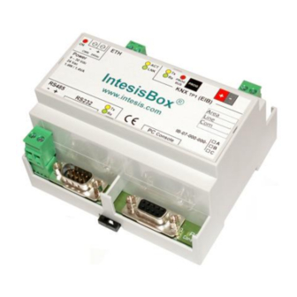
Modbus Server – KNX ® User’s Manual r18 eng IntesisBox 4. Connections Modbus TCP master Power KNX TP-1 See technical (Bus EIB) characteristics Ethernet RJ45 Ethernet CMN 24Vac Modbus TCP 9 - 30Vdc KNX TP-1 Max.125 mA 24Vac ® IntesisBox Max.127mA... -
Page 14: Connect To Knx
IntesisBox 4.2 Connect to KNX Connect + and – terminals of the KNX bus to the IntesisBox KNX connector (Figure 4.1). The polarity is important. Once connected correctly the KNX Tx led (Figure 4.1) will start blinking. If that doesn’t happen check that the cable is connected properly. -
Page 15: Connect To Pc (Linkboxmb)
(more information can be found in the LinkBoxMB User Manual [section5].Two methods to connect to the PC can be used: Ethernet: Using the ETH port (Figure 4.1) of IntesisBox. How to check connectivity is explained in section 4.3. ... -
Page 16: Linkboxmb. Configuration & Monitoring Tool For Intesisbox Modbus Server Series
How to install and use the LinkBoxMB is explained in its Manual. It can be found in the installation folder (if the Software is already installed) or it can be downloaded from the link that can be found in the installation sheet supplied with the IntesisBox ®... -
Page 17: Connection Configuration
User’s Manual r18 eng IntesisBox 5.1.1 Connection configuration Two subsets of information are configured using this window, the Modbus TCP & RTU parameters of the IntesisBox ® , and the parameters of the KNX interface. Figure 4.2 Configuration: Connection Tab Modbus interface configuration parameters: Figure 4.3 Modbus TCP &... - Page 18 4. Gateway: Enter the Default Gateway address (router address) in case the gateway (IntesisBox) is in a different sub network than other Modbus devices (supplied by the network administrator). Leave blank if there is no need of router address..
- Page 19 Modbus Server – KNX ® User’s Manual r18 eng IntesisBox KNX interface configuration parameters: Figure 4.4 KNX interface Configuration 1. Physical Address: Enter the KNX physical address for the gateway. 2. Force update: Check this if you want the gateway to update the signals configured as “U”...
- Page 20 IBOX-MBS-KNX-A. Model supporting up to 500 points. IBOX-MBS-KNX-B. Model supporting up to 3000 points. You can identify also the model of your IntesisBox through the identification given by it in response to an INFO? command, it is something like this: IntesisBox_MODBUS_SVR_KNX-100…...
-
Page 21: Signals List
Modbus Server – KNX ® User’s Manual r18 eng IntesisBox 5.1.2 Signals list Select the Signals tab to configure the signals list (the IntesisBox ® internal points). Figure 4.6 Signal list # (Signal’s number) Description Enumeration of the rows in the grid (signals). If clicked on them the whole... - Page 22 Modbus Server – KNX ® User’s Manual r18 eng IntesisBox Description KNX data type (Data point) to encode the signal’s value. It will depend on the Modbus type of signal associated to it in every case .Edit using the mouse right-button-click pop-up menu available on the column Values ...
- Page 23 Modbus Server – KNX ® User’s Manual r18 eng IntesisBox Listening addresses Description KNX group addresses that will be listened by IntesisBox ® for this signal. If IntesisBox ® receives a KNX telegram whose destination is one of these listening addresses, the telegram will be taken into account and the corresponding action will be performed on this signal.
- Page 24 Needs the W flag active and therefore the software activates it automatically When “U” is selected it disables the R flag. Comments DO NOT BE CONFUSED: Philosophy of IntesisBox ® point's U flag is not the same as KNX device's U flag. In KNX devices, U flag means that the point's value will be updated whenever a write telegram for the group address is received by the device.
- Page 25 Modbus Server – KNX ® User’s Manual r18 eng IntesisBox Point (AddMB) Description Modbus register address for the point Values Maximum points accepted by the gateway version: 100 version: from 1 to 100 A version: from 1 to 500 ...
- Page 26 R & U2 can be used simultaneously. When flag U is activated, it is necessary to deactivate R (it is done automatically). Comments NOTE that philosophy of U flag in IntesisBox ® is not the same as in other general KNX equipment. Active...
-
Page 27: Saving The Configuration
To do so open the Configuration window (section 5.1) and restart from step 1. 3. Once in the configuration window again, click on exit. The configuration is ready to be sent to the IntesisBox ® (check LinkBoxMB Manual). The configuration cannot be received from the gateway to LinkBoxMB, it can only be sent. -
Page 28: Intesisbox And Ets
ETS project, for example to allow the line couplers have a correct configuration of their filter tables. To do so a Dummy device can be used in ETS to simulate the IntesisBox ®... -
Page 29: Mechanical & Electrical Characteristics
Modbus Server – KNX ® User’s Manual r18 eng IntesisBox 7. Mechanical & Electrical characteristics. Plastic, type PC (UL 94 V-0). Enclosure Dimensions: 107mm x 105mm x 58mm. Colour Light Grey. RAL 7035. 9 to 30Vdc +/-10%, Max.: 125mA. 24Vac +/-10% 50-60Hz, Max.: 127mA... - Page 30 Modbus Server – KNX ® User’s Manual r18 eng IntesisBox 30 / © Intesis Software S.L.U. - All rights reserved http://www.intesisbox.com This information is subject to change without notice Email info@intesisbox.com +34 938047134 IntesisBox ® is a registered trademark of Intesis Software SLU...
-
Page 31: Dimensions
Modbus Server – KNX ® User’s Manual r18 eng IntesisBox 8. Dimensions. Power External dimensions. Ethernet port port Modbus RTU EIA232/485 Console 58 mm port 107 mm 105 mm Free space recommended to install the device, with spacing enough for external connections.
Need help?
Do you have a question about the IBOX-MBS-KNX-100 and is the answer not in the manual?
Questions and answers