Table of Contents
Advertisement
Quick Links
Advertisement
Table of Contents

Subscribe to Our Youtube Channel
Related Manuals for IntesisBox IBOX-MBS-TCP2RTU


Summary of Contents for IntesisBox IBOX-MBS-TCP2RTU
- Page 1 ® IntesisBox Modbus TCP Server Modbus RTU Master User Manual r1 eng...
- Page 2 ® Modbus Server – Modbus RTU Master IntesisBox User’s Manual r1 eng © Intesis Software S.L. 2013 All Rights Reserved. Information in this document is subject to change without notice. The software described in this document is furnished under a license agreement or nondisclosure agreement. The software may be used only in accordance with the terms of those agreements.
- Page 3 User’s Manual r1 eng Gateway to communicate with Modbus RTU slaves remotely using several Modbus TCP masters. Order code: IBOX-MBS-TCP2RTU 3 / 15 © Intesis Software S.L. - All rights reserved http://www.intesis.com This information is subject to change without notice Email info@intesis.com...
-
Page 4: Table Of Contents
Connect to Modbus RTU ................. 9 Connect to Connect to Modbus TCP ..............9 Connect to PC (LinkBoxMB) ................10 LinkBoxMB. Configuration & monitoring of IntesisBox Modbus Server series ..11 Project configuration ..................11 5.1.1 Connection configuration ................ 11 5.1.2... -
Page 5: Description
® Modbus Server – Modbus RTU Master IntesisBox User’s Manual r1 eng 1. Description 1.1 Introduction Communicate with Modbus RTU slaves remotely using Modbus TCP, with the advantage of having various Modbus TCP masters accessing the same RTU slaves simultaneously. -
Page 6: Functionality
IntesisBox Modbus RTU communication can work with both EIA232 and EIA485. The baud rate, parity and polling time can be configured. IntesisBox could handle up to 255, but it is strongly recommended not use more than 32 RTU slave devices to avoid communication problems and to ensure integration stability. -
Page 7: Quick Setup
3. Quick Setup 1. Install LinkBoxMB Details in section 5 2. Install IntesisBox in the desired installation site (DIN rail mounting inside a metallic industrial cabinet connected to ground is recommended). 3. Power up and connect the communication cables. Details in section 4 4. -
Page 8: Connection
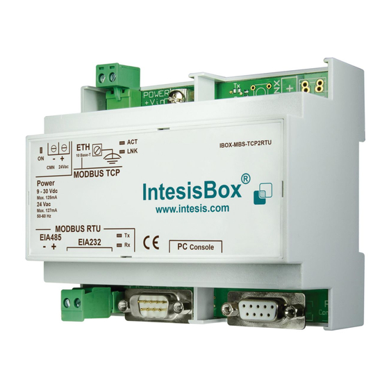
Figure 4.1 Device connection diagram Ensure proper space for all connectors when mounted. The items supplied by Intesis Software for this integration are: IntesisBox Modbus Server – Modbus RTU hardware Console cable. Standard DB9F-DB9M cable 1.8 meter long. ... -
Page 9: Power Device
Manual (section 5). 4.3 Connect to Modbus TCP Connect the communication cable coming from the network hub or switch to the ETH port (Figure 4.1) of IntesisBox. The cable to be used depends on where the IntesisBox is being connected: ... -
Page 10: Connect To Pc (Linkboxmb)
IntesisBox User’s Manual r1 eng In case there is no communication with the IntesisBox IntesisBox, check that the Modbus TCP devices they are operative and reachable from the network connection used by IntesisBox. Check the IntesisBox Ethernet interface sending Pings to its IP address using a PC connected to the same Ethernet network. -
Page 11: Linkboxmb. Configuration & Monitoring Of Intesisbox Modbus Server Series
(if the Software is already installed) or it can be downloaded from the link that can be found in the installation sheet supplied with the IntesisBox. In this section only the specific project configuration for IntesisBox Modbus Server – Modbus RTU Master is going to be explained. - Page 12 Net Mask: Enter the IP net mask for IntesisBox. Gateway: Enter the default router address to use by IntesisBox, leave blank if there is no need of router address. Port: Enter the TCP port to use, by default 502.
-
Page 13: Saving The Configuration
1 3. Once in the configuration window again, click on exit. The configuration is ready to be sent to the IntesisBox (check LinkBoxMB Manual) The configuration cannot be received from the gateway to LinkBoxMB, it can only be sent. -
Page 14: Mechanical & Electrical Characteristics
® Modbus Server – Modbus RTU Master IntesisBox User’s Manual r1 eng 6. Mechanical & electrical characteristics Plastic, type PC (UL 94 V-0). Enclosure Dimensions: 107mm x 105mm x 58mm. Color Light Grey. RAL 7035. 9 to 30Vdc +/-10%, Max.: 125mA. -
Page 15: Dimensions
® Modbus Server – Modbus RTU Master IntesisBox User’s Manual r1 eng Power 7. Dimensions Ethernet Modbus RTU EIA232/485 Console 58 mm port 105 mm 107 mm Recommended available space for its installation into a cabinet (wall or DIN rail mounting), with space...
Need help?
Do you have a question about the IBOX-MBS-TCP2RTU and is the answer not in the manual?
Questions and answers