Table of Contents
Advertisement
Quick Links
Advertisement
Table of Contents

Subscribe to Our Youtube Channel
Summary of Contents for IntesisBox IBMBSKNX1000000
- Page 1 ® IntesisBox Modbus Server User Manual r1.0 eng Issue date: 09/2017...
- Page 2 All trademarks and trade names used in this document are acknowledged to be the copyright of their respective holders. 2/18 http://www.intesisbox.com © Intesis Software S.L.U. - All rights reserved email info@intesisbox.com IntesisBox is a registered trademark of Intesis Software SLU +34 938047134...
- Page 3 IBMBSKNX1000000, 100 points version IBMBSKNX2500000, 250 points version IBMBSKNX6000000, 600 points version IBMBSKNX1K20000, 1200 points version IBMBSKNX3K00000, 3000 points version 3/18 http://www.intesisbox.com © Intesis Software S.L.U. - All rights reserved email info@intesisbox.com IntesisBox is a registered trademark of Intesis Software SLU +34 938047134...
-
Page 4: Table Of Contents
Modbus RTU ........................... 11 Connection to the configuration tool ....................11 5 Set-up process and troubleshooting ...................... 12 Pre-requisites ..........................12 IntesisBox MAPS. Configuration & monitoring tool for IntesisBox KNX series ......12 5.2.1 Introduction ..........................12 5.2.2 Connection ..........................12 5.2.3... -
Page 5: Description
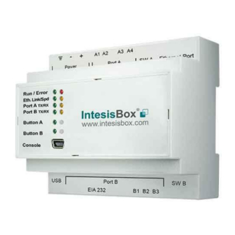
KNX TP-1 (EIB) system and vice-versa. For this, IntesisBox acts as a Modbus TCP server or Modbus RTU slave device in its Modbus interface, allowing read/write points from the Modbus client device(s), and offering this point's values through its KNX interface, acting in the KNX system as one more KNX device of the system. -
Page 6: Functionality
Number of Modbus Number of Modbus Master Master devices devices supported by the device Up to 6 TCP connections 6/18 http://www.intesisbox.com © Intesis Software S.L.U. - All rights reserved email info@intesisbox.com IntesisBox is a registered trademark of Intesis Software SLU +34 938047134... -
Page 7: Knx Interface
2 KNX interface In this section, a common description for all IntesisBox KNX series gateways is given from the point of view of KNX system, which is called from now on external system. The Modbus system is also called from now on internal system. -
Page 8: Modbus Interface
Description IntesisBox acts as a slave device in its Modbus interface, this interface can be the Ethernet port (if using Modbus TCP), or the EIA232/EIA485 ports (if using Modbus RTU). To access the points and resources of the IntesisBox from a Modbus master device, you must specify as Modbus register addresses, those configured inside IntesisBox corresponding to KNX signals. -
Page 9: Points Definition
Every point defined in the gateway has the Modbus Format, Point and R/W features associated to it that can be configured. These features are explained in section 5.2.4. Each point defined in IntesisBox has the following Modbus features associated to it: Feature... -
Page 10: Connections
Connect a USB storage device (not a HDD) if required. Check the user manual for more information. Ensure proper space for all connectors when mounted (see section 7). 10/18 http://www.intesisbox.com © Intesis Software S.L.U. - All rights reserved email info@intesisbox.com IntesisBox is a registered trademark of Intesis Software SLU +34 938047134... -
Page 11: Powering The Device
Connect the communication cable coming from the KNX network hub, or switch, to the ETH port (Figure above) of IntesisBox. In case there is no response from the KNX installation, or KNX devices, to the frames sent by IntesisBox, check that they are operative and reachable from the network connection used by IntesisBox. -
Page 12: Set-Up Process And Troubleshooting
It is necessary to have a KNX installation, device or interface operative and well connected to the corresponding KNX port of IntesisBox and a Modbus RTU slave or Modbus TCP client connected to their corresponding ports as well. Connectors, connection cables, PC to use the configuration tool and other auxiliary material, if needed, are not supplied by Intesis Software SLU for this standard integration. -
Page 13: Configuration Tab
5.2.4 Signals All available objects, Object Instances, its corresponding Modbus register and other main parmaters, are listed in the signals tab. More information on each parameter and how to configure it can be found in the IntesisBox MAPS user manual. -
Page 14: Sending The Configuration To Intesisbox
If NO is selected, remember that the file with the project needs to be generated before the IntesisBox starts to work as expected. 3.- Press the Send File button to send the file to the IntesisBox device. The process of file transmission can be monitored in the IntesisBox Communication Console window. IntesisBox will reboot automatically once the new configuration is loaded. - Page 15 Figure 5.5 Diagnostic More information about the Diagnostic section can be found in the Configuration Tool manual. 15/18 http://www.intesisbox.com © Intesis Software S.L.U. - All rights reserved email info@intesisbox.com IntesisBox is a registered trademark of Intesis Software SLU +34 938047134...
-
Page 16: Set-Up Procedure
Port B of IntesisBox (More details in section 0). 5. Power up IntesisBox. The supply voltage can be 9 to 30 Vdc or just 24 Vac. Take care of the polarity of the supply voltage applied. -
Page 17: Electrical & Mechanical Features
Position 2-3: 100 mm (h) ON: Polarization active Off: Polarization inactive 130 mm (d) 100 mm (w) 17/18 http://www.intesisbox.com © Intesis Software S.L.U. - All rights reserved email info@intesisbox.com IntesisBox is a registered trademark of Intesis Software SLU +34 938047134... -
Page 18: Dimensions
Recommended available space for its installation into a cabinet (wall or DIN rail mounting), with space enough for external connections 100 mm (h) 130 mm (d) 100 mm (w) 18/18 http://www.intesisbox.com © Intesis Software S.L.U. - All rights reserved email info@intesisbox.com IntesisBox is a registered trademark of Intesis Software SLU +34 938047134...


Need help?
Do you have a question about the IBMBSKNX1000000 and is the answer not in the manual?
Questions and answers