Table of Contents
Advertisement
Quick Links
Advertisement
Table of Contents

Subscribe to Our Youtube Channel
Related Manuals for IntesisBox IBBACMEB0100000


Summary of Contents for IntesisBox IBBACMEB0100000
- Page 1 ® IntesisBox BACnet Server M-Bus Meters User Manual r1.0 eng Issue date: 09/2017...
- Page 2 All trademarks and trade names used in this document are acknowledged to be the copyright of their respective holders. 2/41 http://www.intesisbox.com © Intesis Software S.L.U. - All rights reserved email info@intesisbox.com IntesisBox is a registered trademark of Intesis Software SLU +34 938047134...
- Page 3 Order code: IBBACMEB0100000, 10 M-Bus devices IBBACMEB0200000, 20 M-Bus devices IBBACMEB0600000, 60 M-Bus devices IBBACMEB1200000, 120 M-Bus devices 3/41 http://www.intesisbox.com © Intesis Software S.L.U. - All rights reserved email info@intesisbox.com IntesisBox is a registered trademark of Intesis Software SLU +34 938047134...
-
Page 4: Table Of Contents
Connection to M-Bus ........................34 Connection to the configuration tool ....................34 7 Set-up process and troubleshooting ...................... 35 Pre-requisites ..........................35 IntesisBox MAPS. Configuration & monitoring tool for IntesisBox BACnet series ......35 7.2.1 Introduction ..........................35 7.2.2 Connection ..........................35 7.2.3... - Page 5 BACnet Server – M-Bus ® IntesisBox User Manual r1.0 eng 9 Dimensions ............................41 5/41 http://www.intesisbox.com © Intesis Software S.L.U. - All rights reserved email info@intesisbox.com IntesisBox is a registered trademark of Intesis Software SLU +34 938047134...
-
Page 6: Description
(COV) requests and reads/writes to its internal points. From the M-Bus point of view, IntesisBox acts as a M-Bus master device (EN-1434-3), the readings of the M-Bus slave device(s) is performed by IntesisBox by automatic continuous polling. -
Page 7: Functionality
With every read, the new values received are updated in the Intesisbox's memory and become available in the BACnet side. When a change in any point configured as output in IntesisBox is detected (this is written from the BACnet side), the corresponding action in the M-Bus device will be performed. -
Page 8: Signals
Number of M-Bus signals (readings in the 1500 3000 signals meters) that can be read from IntesisBox. 8/41 http://www.intesisbox.com © Intesis Software S.L.U. - All rights reserved email info@intesisbox.com IntesisBox is a registered trademark of Intesis Software SLU +34 938047134... -
Page 9: Protocol Implementation Conformance Statement
Point-To-Point, EIA 232 (Clause 10), baud rate(s): Point-To-Point, modem, (Clause 10), baud rate(s): LonTalk, (Clause 11), medium: _____ Other: 9/41 http://www.intesisbox.com © Intesis Software S.L.U. - All rights reserved email info@intesisbox.com IntesisBox is a registered trademark of Intesis Software SLU +34 938047134... -
Page 10: Device Address Binding
If this product is a communication gateway, describe the types of non-BACnet equipment/network(s) that the gateway supports: M-Bus slave devices. 10/41 http://www.intesisbox.com © Intesis Software S.L.U. - All rights reserved email info@intesisbox.com IntesisBox is a registered trademark of Intesis Software SLU +34 938047134... -
Page 11: Bacnet Interoperability Building Blocks Supported (Bibbs)
Alarm and Event-Information–A GetEventInformation AE-INFO-B Alarm and Event-Information–B GetEventInformation AE-LS-A Alarm and Event-LifeSafety–A LifeSafetyOperation AE-LS-B Alarm and Event-LifeSafety–B LifeSafetyOperation 11/41 http://www.intesisbox.com © Intesis Software S.L.U. - All rights reserved email info@intesisbox.com IntesisBox is a registered trademark of Intesis Software SLU +34 938047134... -
Page 12: Scheduling Bibbs
Network Management - Router Configuration–A Network Initialize-Routing-Table Initialize-Routing-Table-Ack Who-Is-Router-To-Network I-Am-Router-To-Network NM-RC-B Network Management - Router Configuration–B Initialize-Routing-Table Initialize-Routing-Table-Ack 12/41 http://www.intesisbox.com © Intesis Software S.L.U. - All rights reserved email info@intesisbox.com IntesisBox is a registered trademark of Intesis Software SLU +34 938047134... -
Page 13: Device Management Bibbs
DM-VT-A Device Management - Virtual Terminal–A VT-Close VT-Data VT-Open DM-VT-B Device Management - Virtual Terminal–B VT-Close VT-Data 13/41 http://www.intesisbox.com © Intesis Software S.L.U. - All rights reserved email info@intesisbox.com IntesisBox is a registered trademark of Intesis Software SLU +34 938047134... -
Page 14: Service Types
Security Services RequestKey I-Am I-Have UnconfirmedCOVNotification UnconfirmedEventNotification UnconfirmedPrivateTransfer UnconfirmedTextMessage Unconfirmed TimeSynchronization Services UtcTimeSynchronization Who-Has Who-Is LifeSafetyOperation SubscribeCOVProperty GetEventInformation 14/41 http://www.intesisbox.com © Intesis Software S.L.U. - All rights reserved email info@intesisbox.com IntesisBox is a registered trademark of Intesis Software SLU +34 938047134... -
Page 15: Objects
Calendar Command Device Event-Enrollment File Group Life-Safety-Point Life-Safety-Zone Loop Multistate-Input Multistate-Output Multistate-Value Notification-Class Program Schedule Trend-Log Trend-Log-Multiple 15/41 http://www.intesisbox.com © Intesis Software S.L.U. - All rights reserved email info@intesisbox.com IntesisBox is a registered trademark of Intesis Software SLU +34 938047134... -
Page 16: Objects And Properties
UTC_Offset INTEGER Daylight_Savings_Status BOOLEAN APDU_Segment_Timeout Unsigned 3000 APDU_Timeout Unsigned 3000 Number_of_APDU_ Unsigned Retries List of List_Of_Session_Keys BACnetSessionKey 16/41 http://www.intesisbox.com © Intesis Software S.L.U. - All rights reserved email info@intesisbox.com IntesisBox is a registered trademark of Intesis Software SLU +34 938047134... - Page 17 Interval_Offset Unsigned Profile_Name CharacterString * Only available when MSTP is used ** Configurable through the configuration tool. 17/41 http://www.intesisbox.com © Intesis Software S.L.U. - All rights reserved email info@intesisbox.com IntesisBox is a registered trademark of Intesis Software SLU +34 938047134...
-
Page 18: Analog Input Object Type
BACnetArray[N] of Event_Time_Stamps BACnetTimeStamp Profile_Name CharacterString * Only available when specific object has a Notification Class configured 18/41 http://www.intesisbox.com © Intesis Software S.L.U. - All rights reserved email info@intesisbox.com IntesisBox is a registered trademark of Intesis Software SLU +34 938047134... -
Page 19: Analog Output Object Type
BACnetArray[N] of Event_Time_Stamps BACnetTimeStamp Profile_Name CharacterString * Only available when specific object has a Notification Class configured 19/41 http://www.intesisbox.com © Intesis Software S.L.U. - All rights reserved email info@intesisbox.com IntesisBox is a registered trademark of Intesis Software SLU +34 938047134... -
Page 20: Analog Value Object Type
BACnetArray[N] of Event_Time_Stamps BACnetTimeStamp Profile_Name CharacterString * Only available when specific object has a Notification Class configured 20/41 http://www.intesisbox.com © Intesis Software S.L.U. - All rights reserved email info@intesisbox.com IntesisBox is a registered trademark of Intesis Software SLU +34 938047134... -
Page 21: Binary Input Object Type
BACnetArray[N] of Event_Time_Stamps BACnetTimeStamp Profile_Name CharacterString * Only available when specific object has a Notification Class configured 21/41 http://www.intesisbox.com © Intesis Software S.L.U. - All rights reserved email info@intesisbox.com IntesisBox is a registered trademark of Intesis Software SLU +34 938047134... -
Page 22: Binary Output Object Type
BACnetArray[N] of Event_Time_Stamps BACnetTimeStamp Profile_Name CharacterString * Only available when specific object has a Notification Class configured 22/41 http://www.intesisbox.com © Intesis Software S.L.U. - All rights reserved email info@intesisbox.com IntesisBox is a registered trademark of Intesis Software SLU +34 938047134... -
Page 23: Binary Value Object Type
BACnetArray[N] of Event_Time_Stamps BACnetTimeStamp Profile_Name CharacterString * Only available when specific object has a Notification Class configured 23/41 http://www.intesisbox.com © Intesis Software S.L.U. - All rights reserved email info@intesisbox.com IntesisBox is a registered trademark of Intesis Software SLU +34 938047134... -
Page 24: Multistate Input Object Type
BACnetArray[N] of Event_Time_Stamps BACnetTimeStamp Profile_Name CharacterString * Only available when specific object has a Notification Class configured 24/41 http://www.intesisbox.com © Intesis Software S.L.U. - All rights reserved email info@intesisbox.com IntesisBox is a registered trademark of Intesis Software SLU +34 938047134... -
Page 25: Multistate Output Object Type
BACnetArray[N] of Event_Time_Stamps BACnetTimeStamp Profile_Name CharacterString * Only available when specific object has a Notification Class configured 25/41 http://www.intesisbox.com © Intesis Software S.L.U. - All rights reserved email info@intesisbox.com IntesisBox is a registered trademark of Intesis Software SLU +34 938047134... -
Page 26: Multistate Value Object Type
BACnetArray[N] of Event_Time_Stamps BACnetTimeStamp Profile_Name CharacterString * Only available when specific object has a Notification Class configured 26/41 http://www.intesisbox.com © Intesis Software S.L.U. - All rights reserved email info@intesisbox.com IntesisBox is a registered trademark of Intesis Software SLU +34 938047134... -
Page 27: Calendar Object Type
Tool Object_Type BACnetObjectType CALENDAR (6) Description CharacterString Present_Value BOOLEAN Date_List BACnetLIST of BACnetCalendarEntry Profile_Name BACnetARRAY[N] of BACnetPropertyIdentifier 27/41 http://www.intesisbox.com © Intesis Software S.L.U. - All rights reserved email info@intesisbox.com IntesisBox is a registered trademark of Intesis Software SLU +34 938047134... -
Page 28: Schedule Object Type
Notify_Type BACnetARRAY[3] of Event_Time_Stamps BACnetTimeStamp BACnetARRAY[3] of Event_Message_Texts CharacterString BACnetARRAY[3] of Event_Message_Texts_Config CharacterString BOOLEAN Reliability_Evaluation_Inhibit CharacterString Profile_Name 28/41 http://www.intesisbox.com © Intesis Software S.L.U. - All rights reserved email info@intesisbox.com IntesisBox is a registered trademark of Intesis Software SLU +34 938047134... -
Page 29: Notification Class Object Type
NOTIFICATION_CLASS (15) Description CharacterString Notification_Class Unsigned Priority BACnetARRAY[3] of Unsigned Ack_Required BACnetEventTransitionBits Recipient_List BACnetLIST of BACnetDestination Profile_Name CharacterString 29/41 http://www.intesisbox.com © Intesis Software S.L.U. - All rights reserved email info@intesisbox.com IntesisBox is a registered trademark of Intesis Software SLU +34 938047134... -
Page 30: Trend Log Object Type
Profile_Name CharacterString Logging_Type BACnetLoggingType Status_Flags BACnetStatusFlags * Only available when specific object has a Notification Class configured 30/41 http://www.intesisbox.com © Intesis Software S.L.U. - All rights reserved email info@intesisbox.com IntesisBox is a registered trademark of Intesis Software SLU +34 938047134... -
Page 31: Trend Log Multiple Object Type
Profile_Name CharacterString Logging_Type BACnetLoggingType Status_Flags BACnetStatusFlags * Only available when specific object has a Notification Class configured 31/41 http://www.intesisbox.com © Intesis Software S.L.U. - All rights reserved email info@intesisbox.com IntesisBox is a registered trademark of Intesis Software SLU +34 938047134... -
Page 32: Connections
Connect a USB storage device (not a HDD) if required. Check the user manual for more information. Ensure proper space for all connectors when mounted (see section 9). 32/41 http://www.intesisbox.com © Intesis Software S.L.U. - All rights reserved email info@intesisbox.com IntesisBox is a registered trademark of Intesis Software SLU +34 938047134... -
Page 33: Powering The Device
IntesisBox. The cable to be used shall be a straight Ethernet UTP/FTP CAT5 cable In case there is no response from the BACnet devices to the frames sent by IntesisBox, check that they are operative and reachable from the network connection used by IntesisBox. Check the IntesisBox Ethernet interface sending Pings to its IP address using a PC connected to the same Ethernet network. -
Page 34: Connection To M-Bus
Remember that the IntesisBox provides 36VDC M-Bus voltage to the bus, acting as a M-Bus level converter as well. In case there is no response from the M-Bus device(s) to the frames sent by IntesisBox, check that they are operative and reachable from the network connection used by IntesisBox. -
Page 35: Set-Up Process And Troubleshooting
It is necessary to have a BACnet IP client or MSTP device operative and well connected to the corresponding BACnet port of IntesisBox and a Modbus RTU slave or Modbus TCP client connected to their corresponding ports as well. Connectors, connection cables, PC to use the configuration tool and other auxiliary material, if needed, are not supplied by Intesis Software SLU for this standard integration. -
Page 36: Configuration Tab
7.2.4 Signals All available objects, Object Instances, its corresponding Modbus register and other main parmaters are listed in the signals tab. More information on each parameter and how to configure it can be found in the IntesisBox MAPS user manual. -
Page 37: Sending The Configuration To Intesisbox
If NO is selected, remember that the binary file with the project needs to be generated before the IntesisBox starts to work as expected. 3.- Press the Send File button to send the binary file to the IntesisBox device. The process of file transmission can be monitored in the IntesisBox Communication Console window. IntesisBox will reboot automatically once the new configuration is loaded. - Page 38 Figure 7.5 Diagnostic More information about the Diagnostic section can be found in the Configuraion Tool manual. 38/41 http://www.intesisbox.com © Intesis Software S.L.U. - All rights reserved email info@intesisbox.com IntesisBox is a registered trademark of Intesis Software SLU +34 938047134...
-
Page 39: Set-Up Procedure
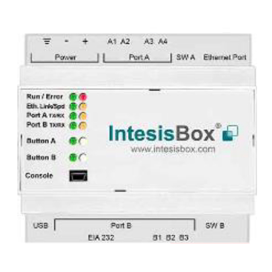
4. Connect the M-Bus communication cable coming from the M-Bus network to the port marked as Port A on IntesisBox (More details in section 0). 5. Power up IntesisBox. The supply voltage can be 9 to 30 Vdc or just 24 Vac. Take care of the polarity of the supply voltage applied. -
Page 40: Electrical & Mechanical Features
100 mm Switch B Off: 120 Ω termination inactive (SWB) Position 2-3: ON: Polarization active Off: Polarization inactive 40/41 http://www.intesisbox.com © Intesis Software S.L.U. - All rights reserved email info@intesisbox.com IntesisBox is a registered trademark of Intesis Software SLU +34 938047134... - Page 41 Recommended available space for its installation into a cabinet (wall or DIN rail mounting), with space enough for external connections 100 mm (h) 130 mm (d) 100 mm (w) 41/41 http://www.intesisbox.com © Intesis Software S.L.U. - All rights reserved email info@intesisbox.com IntesisBox is a registered trademark of Intesis Software SLU +34 938047134...
Need help?
Do you have a question about the IBBACMEB0100000 and is the answer not in the manual?
Questions and answers