
Related Manuals for Arbiter Systems 1092A


Summary of Contents for Arbiter Systems 1092A
- Page 1 MODEL 1092A/B/C MODEL 1093A/B/C SATELLITE-CONTROLLED CLOCK OPERATION MANUAL ARBITER SYSTEMS, INC. PASO ROBLES, CA 93446 U.S.A. WWW.ARBITER.COM...
- Page 2 SETUP key at power-up and the date should appear briefly on the LCD display. To display the firmware date for Models 1092A, 1092C and 1093A, use the main RS-232 port (see page 10.2.15). To determine the current firmware date for this product, see the Arbiter website under the specific product name.
- Page 3 See Contact Information on page ii. “Limited Lifetime” means that Arbiter Systems will repair or replace the defective component as long as com- ponents are available and for no more than five years after the product has been deemed obsolete.
- Page 5 Appendix A Specifications and Technical Details Appendix B Using a Surge Arrester Appendix C Options List Appendix D CE Mark Certification Appendix E Statement of Compliance Index Copyright Arbiter Systems Incorporated February 2016 All rights reserved. International copyright secured. PD0021000AH...
-
Page 6: Table Of Contents
Mounting Instructions ....... 1.4.2 Rack-Mount Ears for Model 1092A/B/C Series Clocks ... . . 2 Front and Rear Panels 2.1 Introduction . - Page 7 CONTENTS 4 GPS Antenna and Cable Information 4.1 GPS Antenna Installation ....... . . 14 4.1.1 Mounting the Antenna .
- Page 8 viii CONTENTS 7 The Setup Menus 7.1 To Begin Configuring ........31 7.2 Setup Menus .
- Page 9 CONTENTS 8.4.3 Synchronizing Multiple IED’s From One Masterclock Output ..54 8.4.4 Connecting Unmodulated IRIG-B ......55 8.4.5 Connecting Modulated IRIG-B .
- Page 10 CONTENTS A Technical Specifications and Operating Parameters A.1 Scope ..........88 A.2 Receiver Characteristics .
- Page 11 CONTENTS C Options List C.1 Introduction ......... 97 C.2 Option 01: Backlighted LCD Display .
- Page 12 CONTENTS C.13.2 Specifications ........126 C.13.3 Firmware Configuration .
- Page 13 1.2 Attaching Rack-Mount Ears ....... . 2.1 Model 1092A/B/C and 1093A/B/C Front Panel Description ....
- Page 14 LIST OF FIGURES 7.14 Slow Code Setup ........44 7.15 Pulse Polarity Setup .
- Page 15 LIST OF FIGURES C.32 System Configure Page Using SSH ......157 C.33 Configure System Password Using SSH ......158 C.34 Checking Network Status Using SSH .
- Page 16 List of Tables 2.1 Command Key Definitions ....... . . 3.1 Available IEC-320 Cordsets by Country .
- Page 17 LIST OF TABLES xvii C.6 Option 28 B2 Broadcast, Time Deviation Values ....122 C.7 Output Connectors and Setup Jumpers ......128 C.8 Option 32/33 Jumper Truth Table .
- Page 18 xviii LIST OF TABLES...
-
Page 19: Unpacking The Clock
Use care when handling. Remember to store the antenna in a safe place before the final installation. Static Discharge Note that the Model 1092A/B/C and 1093A/B/C are electronic devices and use static-sensitive components in their operation. Therefore, use care when handling against static discharges. -
Page 20: Unpacking And Locating Accessories
The Model 1093A/B/C, and included accessories, are packed between two closed-cell foam shells (see Figure 1.1). The Model 1092A/B/C series clocks are packed between layers of molded foam pieces. Carefully pull apart the two shells to extract the clock and accessories. Some of the accessories (i.e. -
Page 21: Rack-Mount Ears For Model 1092A/B/C Series Clocks
1.4.2 Rack-Mount Ears for Model 1092A/B/C Series Clocks Rack-mount ears are available for Model 1092A/B/C series clocks by ordering part number AS0044500. These ears are similar to the rack-mount ears for 1093A/B/C, however the ears are wider to accommodate the narrower width of these clocks. Check with Arbiter sales or your local... -
Page 22: Front And Rear Panels
Introduction This section identifies the connectors, controls, and displays found on the front and rear panels of the 1092A/B/C and 1093A/B/C series clocks. Take care to review all of these items prior to connecting cables to and configuring these products. -
Page 23: Front Panel Controls And Indicators
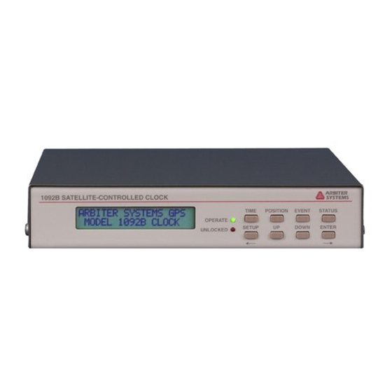
2.2 Front Panel Controls and Indicators Front Panel Controls and Indicators The front panels of the Model 1092A/B/C and 1093A/B/C series clocks are different from one another because of the arrangement of LED indicators, display(s) and keypad. See Figure 2.1 to see the difference between these models. -
Page 24: Lcd Display
2.2.4 Enabling and Disabling the Keypad and Display The Model 1093A/B/C and 1092A/B/C also have one or more RS-232 ports that provide control over the operation of the keypad and display (lock, enable, blank). Refer to Section 10.2.7, in the Serial Communication and Command Set, for a detailed description of RS-232 commands to control the front panel. -
Page 25: Rear Panel Identification And Connectors
Rear Panel Identification and Connectors This section contains information to assist you in identifying where to connect inlet power, the GPS antenna cable and all of the input and output cables on the Model 1092A/B/C and 1093A/B/C series clocks. Figure 2.2: Model 1092A/B/C and 1093A/B/C Rear Panel Description* *Note: Optional outputs may be shown. -
Page 26: Antenna Input
2.3.4 RS-232 and RS-485 Communication Ports The Model 1092A/B/C and 1093A/B/C each have one standard and one optional communication port with RS-232 supported. RS-485 is supported only on the standard RS-232 port, not the optional RS-232 port. The RS-232 port does not use flow control and the RS-485 is transmit only (uses Transmit A and Transmit B, no Receive A and Receive B). -
Page 27: Form C, Relay Contacts - Option 93
Optional Form C relay contacts provide contact closure for an out-of-lock condition, or loss of inlet power. Installing Option 93 gives the Model 1092A/B/C and Model 1093A/B/C one set of Form C relay contacts with three contact points labeled ERR (Normally Closed), OK (Normally Open) and COM;... -
Page 28: Connecting Inlet Power, Input And Output Signals
Output Signals Model 1092A/B/C Model 1092A/B/C series clocks include an external wall-mount power supply with an output of +9 VDC at 500 mA. The Model 1092A/B/C has an input voltage range from +8 to +15 VDC. Model 1093A/B/C To provide for a wide range of inlet power sources, the 1093B can be ordered with any one of three different power inlet modules. -
Page 29: Option 08, 10 To 60 Vdc Terminal Power Strip
3.2 Option 08, 10 to 60 VDC Terminal Power Strip Country Specification Rating Continental Europe CEE 7/7 220V Australia, NZ, PRC AS3112-1981 240V U.K. BS 1363 240V Denmark Afsnit 107-2-01 240V India BS 546 220V Israel SI 32 220V Italy CEI 23-16/VII 1971 220V Switzerland... -
Page 30: Option 10, Connecting Inlet Power
Connecting Inlet Power, Input and Output Signals Figure 3.3: Option 10 Power Supply Inlet Description 3.3.1 Option 10, Connecting Inlet Power When wiring this power supply, make sure to first connect an earth ground wire to the terminal strip connector labeled “G” (for ground). After connecting a ground wire, connect the positive and negative leads from the station batteries to the corresponding Option 10 terminals. -
Page 31: Connecting Output Signals
3.5 Connecting Output Signals Connecting Output Signals Output signals may be connected through designated standard or option connector. For standard I/O connectors, see Section 2.3.6. Terminals are Phoenix-type with 5-mm spacing and will accept between 0.25 and 2.5–mm wire diameter. For Options that have terminals for output connectors, see Appendix C for details about those options and connectors. -
Page 32: Gps Antenna And Cable Information
Chapter 4 GPS Antenna and Cable Information The Model 1092A/B/C and 1093A/B/C come complete with the necessary hardware to be able to receive GPS signals: 50-feet of RG-6 cable and a GPS antenna. Longer cables are available. The antenna cable is connected between the female F connector on the antenna and the female F connector at the rear panel of the clock. -
Page 33: Optional Antenna Mounting Bracket, Kit P/N As0044600
Also, the bracket can be mounted to a wall, a roof, or any other flat surface. For complete details on this product request Installation Instructions for Arbiter Systems GPS Antenna Mounting Bracket on document number PD0024700A. All metallic hardware is stainless steel. -
Page 34: Antenna Mounting Bracket
GPS Antenna and Cable Information Figure 4.2: Antenna Mounting Bracket Figure 4.3: Antenna Mounting with AS0044600... -
Page 35: Verifying Antenna And Cable Operation
4.2 Verifying Antenna and Cable Operation Verifying Antenna and Cable Operation A two-color operate LED, located at the base of the antenna, indicates proper antenna operation. GREEN indicates proper operation (i.e. the antenna is getting the correct voltage); AMBER indicates improper operation (i.e. the voltage is low). 4.2.1 Checking the Antenna Voltage The GPS clock provides +5 VDC to the GPS antenna, which is carried through the antenna cable. -
Page 36: Technical Details On Gps Antennas And Cables
GPS Antenna and Cable Information Technical Details on GPS Antennas and Cables 4.4.1 Antenna Cable Length and Loss Considerations Standard Antenna Cable The standard antenna cable assembly included with the clock is constructed using a 15-meter (50-foot) length of RG-6 type low-loss coaxial cable, terminated with male Type F connectors. Optional lengths of RG-6 coax are separately available for longer runs;... -
Page 37: Gps Cable Data And Accessory Information
Available Antenna Cables and Accessories for Longer Runs Arbiter Systems offers longer antenna cables for use with all models of clocks when the standard 15-meter (50-foot) cable is inadequate. For RG-6 cable runs greater than 250 feet, up to 500 feet, Arbiter offers a 21-dB in-line amplifier, P/N AS0044700. - Page 38 GPS Antenna and Cable Information Adjacent Signals Although the standard RG-6 style cable is triple-shielded and has excellent shielding properties, be cautious when routing near high power RF sources or alongside cables carrying high power RF, such as transmitter cables. In these applications, consider using RG-11 style cable (P/N WC0004900). Its quad-shielded design provides even more isolation.
-
Page 39: Setting Internal Jumpers
Setting Internal Jumpers Introduction Jumpers in the the 1092A/B/C and 1093A/B/C series clocks are normally set up at the factory according default settings, or according to the purchase order if requested. If it should be necessary to change any jumpers or to enable an alternate function, follow the instructions in this chapter. -
Page 40: Output Signal Type, Jmp3 And Jmp4
Setting Internal Jumpers Figure 5.1: Main board and Jumper Locations 5.3.1 Output Signal Type, JMP3 and JMP4 Jumpers JMP3 and JMP4 may be installed to change the output signal type available at I/O connector J4. Before installing either of these jumpers, the drill-out via under the jumper location must be broken, using a small drill in a pin-vise or a sharp blade (such as an X-Acto knife). -
Page 41: Change Unmodulated Irig-B To Programmable Pulse
5.3.4 I/O Connector Used as Event Capture Input, JMP7 With modification, the Model 1092A/B/C and 1093A/B/C can accept an Event Capture input through connectors J4 or J6 (I/O and RS-232 respectively). See Figure 5.1. To select the RS-232 input from J6, set jumper JMP7 to the “A” position . -
Page 42: Output Signal Select, Jmp1 And Jmp2
Setting Internal Jumpers For RS-232C Event Trigger Operation, it is necessary to configure the clock as described in Section 9.2.8, “RS-232C Event Trapping.” 5.3.5 Output Signal Select, JMP1 and JMP2 JMP1 and JMP2 (available only if the 200 V open-drain outputs have been installed) select between the standard surge-protected 5 V CMOS drivers (position A) and the 200 V open-drain FET drivers (position B). -
Page 43: Startup And Basic Operation
Startup behavior is based on Models 1092B and 1093B/C clocks with a display. Startup behavior for the 1092A and 1093A models have no visible display other than two annunciator LEDs. For the 1092A and 1093A, time and position (and other) data may be viewed if monitoring through a RS-232 port. Model 1092C has two annunciator LEDs and nine-digit LED time display. -
Page 44: Clock Time, Startup Mode - 1092B, 1093B/C
(if equipped with Option 93). Front Panel Indication – 1092B, 1093B/C 6.2.1 Display Indication at Startup In the startup sequence, the LCD display should indicate clock status as follows: ARBITER SYSTEMS GPS SUBSTATION CLOCK followed by: COPYRIGHT (C) 2010 ARBITER SYSTEMS, INC. -
Page 45: Other Display Indications When Unlocked
6.2 Front Panel Indication – 1092B, 1093B/C After this, the second line of the status display should change to UNLOCKED, or LOCKED depending on the previous operation, inactivity or if the clock has been moved. During startup, the Unlocked LED should remain extinguished after the GPS receiver begins tracking satellites. 6.2.2 Other Display Indications When Unlocked Time Display... -
Page 46: Irig-B Time Data
Startup and Basic Operation for DEVIATION, it will indicate the 1-PPS Deviation (updates once per second) and Sigma. If there are no records, the second line will indicate “NO DATA”. Event Display Ch A EVENT nnn ddd:hh:ss.sssssss Where: nnn = event number(001 to 400) ddd = day of year of the event(1 to 366) hh = hour of the event(00 to 23) mm = minute of the event(00 to 59) -
Page 47: Date And Time Display, Universal Time Coordinated (Utc)
6.4 Time Display Modes – 1092B and 1093B/C Time Definitions: www = Day of the Week (Sun – Sat); dd = the Day of the Month (1 – 31); ddd = the Day of Year (1 – 366); mmm = the Month (Jan – Dec); yyyy = the Year (e.g. 2007); hh = the Hour (00 –... -
Page 48: Daylight Saving Time/Summer Time (Dst)
Startup and Basic Operation 6.4.5 Daylight Saving Time/Summer Time (DST) The Daylight Saving Time/Summer Time (DST) configuration feature allows expanded settings. The addition of AUTO allows the user to customize the DST settings to match the requirements of locations in either Northern or Southern latitudes. DST configuration may be changed through the serial port or through the front panel keypad. -
Page 49: The Setup Menus
(2) remotely, using either the main RS-232 port or option RS-232 port. To configure Models 1092A/C and 1093A, you must use the RS-232 port(s). Both methods are described in this section. For complete information on configuring all clocks remotely through either serial port, please refer to Chapter 10, Serial Communication and Command Set. -
Page 50: Setup Menus
The Setup Menus Setup Menus Setup Menus Setup Items Set Main RS-232? Main RS-232 Port Parameters and Broadcast Set Local Hour? Set Local Offset, Daylight Saving mode Set Out-Of-Lock? Set Time Interval Before Alarm Set Back Light? Set to ON, OFF or AUTO Set System Delays? Set Antenna Cable Delay in Nanoseconds Set Prog. -
Page 51: To Exit Setup Menus
RS-232 port parameters (See Figure 7.1). To set up the broadcast mode, press SETUP and skip to Section 7.3.2 below. NOTE: port settings may not be changed in the 1092A/C and 1093A series clocks since they do not have a keypad, and there are no port setting commands. -
Page 52: Setting Port Parameters
The Setup Menus 7.3.1 Setting Port Parameters The “Set Port Config” menu allows you to configure any of the RS-232 port parameters from the front panel. Use the UP and DOWN keys to adjust the parameter values. For RS-232 command, Port parameters may not be changed from RS-232C ports. -
Page 53: Setting The Local Hour
7.4 Setting the Local Hour Setting the Local Hour Use “Set Local Hour” to set the offset in time from UTC to your locale and any Daylight Saving settings if they apply. Offsets may be adjusted in 15-minute increments, up to plus or minus 12 hours. -
Page 54: Set Daylight Saving Time (Dst)
The Setup Menus 7.4.1 Set Daylight Saving Time (DST) Use the “Set Daylight Saving Time” menu to configure the one-hour offset to “Local Hour” settings. For automatic changeover, use the AUTO setting explained above. Make sure to determine the changeover requirements in your locale before trying to adjust the settings. The default setup is for North America, where DST begins on the second Sunday of March at 2 am and ends on the first Sunday of November at 2 am. -
Page 55: Setting Out Of Lock
7.5 Setting Out of Lock Setting Out of Lock Use the “Set Out of Lock” feature to control how the clock responds to an out-of-lock condition. Out of lock means that the GPS receiver in the clock is no longer tracking any satellites and that the time may drift according to characteristics of the internal clock and environmental conditions. -
Page 56: Setting The Back Light
The Setup Menus Setting the Back Light If the optional back light (Option 01) is installed in the clock, use the “Set Back Light” menu to configure how the back light operates. If back light is not installed, then the “Set Back Light” menu will have no effect. -
Page 57: Setting Programmable Pulse Mode
7.8 Setting Programmable Pulse Mode Setting Programmable Pulse Mode Use the “Set Prog. Pulse” menu to set up one of the many pulse modes, in which you can broadcast a pulse over one of the standard outputs (I/O) at a predetermined interval or rate. Also, there is a “pulse-per-day”... -
Page 58: Programmable Pulse - Seconds-Per-Pulse Mode
The Setup Menus 7.8.2 Programmable Pulse – Seconds–Per–Pulse Mode Use the “Seconds–Per–Pulse” mode to generate a pulse every X number of seconds, from 1 to 60,000 seconds, and a Pulse Width of from 10 milliseconds to 600 seconds. Refer to Section 7.8 above for additional detail on the Programmable Pulse mode. -
Page 59: Programmable Pulse - Pulse-Per-Hour Mode
7.8 Setting Programmable Pulse Mode 7.8.3 Programmable Pulse – Pulse–Per–Hour Mode Use the “Pulse–Per–Hour” mode to generate a pulse every hour, at the number of specified sec- onds (from 0 to 3599 seconds) after the hour. Refer to Section 7.8 above for additional detail on the programmable pulse modes, and entering numerical values. -
Page 60: Programmable Pulse - Pulse-Per-Day Mode
The Setup Menus 7.8.4 Programmable Pulse – Pulse–Per–Day Mode Use the “Pulse–Per–Day” mode to generate a pulse every day, at the specified hour, minute, second and fractional seconds. Refer to Section 7.8 above for additional detail on the Programmable Pulse mode, and entering numerical values. -
Page 61: Programmable Pulse - Single Trigger
7.8 Setting Programmable Pulse Mode 7.8.5 Programmable Pulse – Single Trigger Use the “Single Trigger” mode to generate a pulse once per year at the specified Julian Day, hour, minute, second and fractional seconds. For reference, many calendars indicate the Julian Day. Refer to Section 7.8 above for additional detail on the Programmable Pulse mode, and entering numerical values. -
Page 62: Programmable Pulse - Slow Code
The Setup Menus 7.8.6 Programmable Pulse – Slow Code The “Slow Code” mode causes the output voltage to be held high and go low for six seconds on the day, four seconds on the hour and two seconds on the minute. For RS-232 command, see Section 10.2.12. -
Page 63: Setting Irig Time Data
7.9 Setting IRIG Time Data Setting IRIG Time Data Use the “Set IRIG Time Data” menu to adjust the time for IRIG-B Time Data from UTC to Local, and to turn ON or OFF the IEEE-1344 extension. The IEEE-1344 extension controls some additional information contained in the IRIG-B time code (see Section 8.3.3). -
Page 64: Setting The Auto Survey Mode
The Setup Menus 7.11 Setting the Auto Survey Mode Use one of the Auto Survey modes to control how and when the clock determines position infor- mation. The accuracy of the position (and indirectly, time) is based on averaging the assigned number of position fixes surveyed, either during startup or by a single survey. -
Page 65: Setting Position Hold On Or Off
7.12 Setting Position Hold ON or OFF 7.12 Setting Position Hold ON or OFF With Position Hold turned ON, the surveyed position is placed into memory and used for computing more precise timing solutions. With Position Hold turned OFF, the GPS receiver is placed in the Fix mode, calculating a new position approximately every second as long as the GPS receiver is tracking four or more satellites. -
Page 66: Setting Option Control
The Setup Menus 7.13 Setting Option Control Use the “Set Option Control” menu to configure any main board or auxiliary board option mounted in the clock. Some of these options require you to configure additional settings. For information on configuring specific options see the Option List located in Appendix C. For RS-232 command, see Section 10.2.15. -
Page 67: Timing, Irig-B And Pulses
Timing Output Description When viewing the rear panels of the Model 1092A/B/C and 1093A/B/C, you will see a number of different types of connectors as illustrated in Figure 8.1. Generally, there is a power inlet connector, a GPS antenna connector, two DB-9 serial connectors (one is an optional RS-232 port), one optional SPDT relay connector, one optional and two standard timing outputs. -
Page 68: Inputs And Outputs - Port 1, Port 2, Port 3
Timing, IRIG-B and Pulses Figure 8.1: Rear Panel Descriptions – optional outputs may be shown 8.2.1 Inputs and Outputs – Port 1, Port 2, Port 3 Three, Phoenix-style, terminal connectors can supply timing signals to external equipment and may also be configured for input. Two of the outputs (Ports 1 & 3) are designed for digital signals and one (Port 2) for analog. -
Page 69: Output Signal Description
The Model 1092A/B/C and 1093A/C transmit (IRIG) Format B with four variations as seen in Table 8.2. Note that with the newer IRIG Standard 200-04, two of the designations have changed: the older B000 has become B004 and B120 has become B124. -
Page 70: Modulated And Unmodulated Irig-B
Timing, IRIG-B and Pulses 8.3.2 Modulated and Unmodulated IRIG-B Figure 8.2 illustrates the primary differences between modulated and unmodulated IRIG-B. You will notice that the while modulated IRIG-B is distinctive because of the 1 kHz sinewave carrier, it is similar to unmodulated IRIG-B since the peak-to-peak values of the carrier follow the same form as the peaks of the digital waveform, which contain the information. -
Page 71: Programmable Pulse (Prog Pulse)
firmware configuration. Models 1093B/C and 1092B may be configured from the front panel and 1092A/C and 1093A must be configured through the RS-232 port. There are many available programmable pulse modes from which to choose that include setting the pulse width and time zone. -
Page 72: Connecting The Outputs
Timing, IRIG-B and Pulses Connecting the Outputs All clocks come equipped with Phoenix-style, screw terminal connectors, which are compatible with twisted pair cabling. To attach, strip the wires bare, DO NOT tin with solder, insert into the correct screw terminal positions and tighten clockwise. To adapt coaxial cabling to the 1092/93 terminal connectors, use a BNC Breakout , or other similar adapter. -
Page 73: Connecting Unmodulated Irig-B
8.4 Connecting the Outputs 8.4.4 Connecting Unmodulated IRIG-B To drive multiple loads from one unmodulated IRIG-B output, make sure that the loads are wired in parallel. A common term for this is “Daisy-Chaining”, however the idea is to drive all of these loads in parallel from a single output. -
Page 74: Wire Losses
Timing, IRIG-B and Pulses 8.4.6 Wire Losses Another factor affecting the available voltage is the resistive losses through the cabling. Wire has a certain resistivity associated with it that is determined by its metallic composition, and resistance determined by the diameter and length. For example, single-strand, 22 AWG (bare, enamel-coated) copper wire has a resistance of approximately 19.6 ohms per 1000 feet. -
Page 75: Solutions
8.4 Connecting the Outputs Since electromagnetic waves travel slower through any cable, cable manufacturers normally specify cable with a velocity factor (VF), which is a percentage of the speed of light in free space, and characteristic of the specific cable. The Velocity Factor for the RG-6 cabling used by Arbiter Systems for GPS antenna connections, is about 83% of C. -
Page 76: Relay Contacts And Event Inputs
9.1.1 Introduction Option 93 provides a single set of SPDT relay contacts when installed the Model 1092A/B/C or 1093A/B/C. Without Option 93 installed, the relay contact connector will be visible, however no contacts or related circuitry will be installed. To retrofit the Option 93, Out-of-Lock relay, you must arrange to return it to the factory for installation. -
Page 77: Event Timing Latency
RS-232. 9.2.5 Event Timer Input Channel Configuration In order for the Model 1092A/B/C or 1093A/B/C to receive a timing input, adjustments to both the hardware and software configuration may be required. The hardware configuration is described in Section 5.3.4. -
Page 78: Firmware Setup
Relay Contacts and Event Inputs 9.2.6 Firmware Setup Reconfiguration of the firmware may also be required to allow measurement and display of Event Time Data and/or 1 PPS Deviation. See Figure 7.17 for detail on configuring the Event/Deviation parameters from the front panel. See Section 10.2.4 for details on using the RS-232 interface. 9.2.7 Displaying Data Event and deviation data can be accessed from either the front panel or via RS-232 com-... -
Page 79: Rs-232C Event Trapping
9.2.8 RS-232C Event Trapping The event capture channel of the Model 1092A/B/C and 1093A/B/C can be configured to capture one or more events via the RS-232C Serial Interface. The time mark for a captured event will correspond to the leading edge of the start bit of the first character in the RS-232C signal. This event mode can be both armed and interrogated for data over the RS-232C interface, allowing automated synchronization of an external computer or system. -
Page 80: Serial Communication And Command Set
10.1 Introduction Models 1092A/B/C and 1093A/B/C have one main RS-232 port, and one optional RS-232 port. These are labeled RS-232C and Option RS-232. When viewing the rear panel, the main port is nearest the antenna connector and the optional port is to the left of the Standard I/O connectors. -
Page 81: Custom String Command
10.2 Command Set decimal point as required. Strings are normally terminated with carriage return and line feed characters, however not always. Enter any RS-232C command as written in these tables without pressing ENTER. Characters are automatically received when typed. If including any of these commands in a programming sequence, do not include any carriage-return or line-feed characters. -
Page 82: Characters Used With Custom Strings
Serial Communication and Command Set Custom Broadcast Character Set Character Meaning / character Cssnn Xor checksum of specified range, where ss = start location (hex value from 00 to FF) and nn = number of bytes (hex value from 00 to FF) Day of month: 01, . -
Page 83: List Of Possible Time Quality Levels, Ordinal 01
10.2 Command Set True/False Condition Command: /[ii? < t > / :< f > /] where: < t > = True condition < f > = False condition ii: 01 = Locked; 02 = Status change; 03 = Locked with max accuracy; 04 = Fault; 05 = Daylight Saving Time change pending;... -
Page 84: String Setup Examples And Tutorial
Serial Communication and Command Set Using Ordinals and Conditionals An ordinal returns an ASCII character or characters (e.g. 1, 2, 3,.., good, bad, etc.) for a requested value (e.g. clock accuracy). A conditional returns an ASCII character or characters (e.g. 0, 1, locked, unlocked, etc.) based on a true/false request (e.g. - Page 85 10.2 Command Set ASCII Standard Desired Output: <soh>ddd:hh:mm:ss Input String Code: @@A/T01/d:/h:/m:/s/r Input String Construction Notes: Note that the ordinary method of starting the ASCII Standard broadcast is using the B1 or O1 command as described on page 69. Custom string entry always begins with the @@A for strings output from the main serial port, or @@B for strings output from the option serial port.
- Page 86 Serial Communication and Command Set Extended ASCII (DTSS MSG) Desired Output: Q yy ddd hh:mm:ss.000 Input String Code: /T0D/H0A/[03? /:?/] /y /d:/h:/m:/s.000 Input String Construction Notes: Note that the ordinary method of starting the Ext. ASCII broadcast is using the B5 or O5 command as described on page 70. “T0D” sets the on time mark as a carriage return, and “H0A”...
-
Page 87: Broadcast Mode Commands
B2 configures the clock to broadcast data formatted for Vorne large format time displays from the main RS-232 port. O2 configures the clock to broadcast from the option RS-232 port Vorne- formatted data. Refer to Arbiter Systems Application Note 103 for more information on using large format displays with GPS clocks from Arbiter Systems. -
Page 88: Fault Indications And Definitions
Serial Communication and Command Set Broadcast Mode – EVENT DATA Command: B3, O3 B3 configures the clock to broadcast from the main RS-232 port any event data at the time it is recorded. O3 configures the clock to broadcast from the option RS-232 port any event data at the time it is recorded. - Page 89 10.2 Command Set Response: Q yy ddd hh:mm:ss.000 Format: Q = Time quality indicator, and may be represented by: = meaning it is locked with maximum accuracy. ? = (ASCII 63) unlocked, accuracy not guaranteed = (space) used for clarity only and graphically represents the location of an ASCII space. Broadcast Mode –...
- Page 90 Serial Communication and Command Set Broadcast Mode – NMEA183GLL Command: 0,nB 0,nB configures the clock to broadcast the National Marine Electronics Association Standard (NMEA - 0183) to broadcast from the main RS-232 port, where n = the update rate in seconds, from 1 to 9999.
- Page 91 10.2 Command Set Response: >900WD:yy-mm-dd hh:mm:ss.fff:cc< CR > yy-mm-dd the current date: yy = year of century, (00. . . 99) mm = month, (1. . . 12) dd = day of month, (01. . . 31) = Space (ASCII 20h) hh:mm:ss.fff the current time: hh = hours, (00.
-
Page 92: Event Mode Commands
Serial Communication and Command Set xPM activates (x = 1) or deactivates (x = 0) the use of the main serial port, pin 6 controlling (by high or low input) the output from pin 3. When used with a modem, the modem can be programmed to toggle HI and LO to effectively free it from domination from a broadcast output from the clock and restore operation. -
Page 93: Status Mode Commands
10.2 Command Set Clear Event Buffer Command: CA CA clears the channel A event buffer and then resets the read and wrote indices to 0. Response: Return Deviation for Event Channel Command: DA DA returns 1-PPS deviation and sigma for the event input. Response: dddd.dd ssss.ss (Results are in microseconds) - Page 94 Serial Communication and Command Set nnn Channel read index (001 to 400) mmm Channel write index (001 to 400) NOTE: When nnn = mmm, using the EA command to read event data, the event buffer is empty, i.e., all event data which has been recorded has also been read. Return Clock Status Command: SC SC returns the current clock status.
-
Page 95: Survey (Sn) / Position-Hold Status (Pm)
10.2 Command Set t = number of satellites being actively tracked (up to twelve) P = Off, indicates that the time dilution of precision (TDOP) calculation is not being performed. Returns 1.0 - 99.0, depending on satellite geometry, when TDOP calculation is being performed. A TDOP calculation is NOT performed if less than 3 satellites are visible, OR if Position-Hold is active. -
Page 96: Local / Daylight Saving Time Setup Commands
Serial Communication and Command Set Response: I=nn:nn X=nn:nn Format: I = internal clock conditions X = external clock conditions nn:nn = hexadecimal representations of the status byte. The two digits preceding the colon describe present condition of the instrument. The two digits after the colon indicate the parameters that have changed. Time Quality Command: TQ TQ returns a single ASCII character (0, 4–9, A, B, F) indicating estimated worst-case time quality,... -
Page 97: Front Panel Control Commands
10.2 Command Set and times. To complete the Daylight Saving / Summer Time setup, you must also use the “Set Daylight Saving Auto Start” and “Stop” commands that follow below. Response: Set Daylight Saving/Summer Auto Start Time Command: 2,w,x,y,zDT 2,w,x,y,zDT sets the starting (Start) date and time for Daylight Saving / Summer Time AUTO setting. -
Page 98: Irig-B Data Output Commands
Serial Communication and Command Set Enable Control Panel Command: FE FE enables all control–panel keys and activates the front panel display – Models 1092B and 1093B/C only. Response: Lock Setup Keys Command: FL FL disables setup control keys and activates the front panel display – Models 1092B and 1093B/C only. -
Page 99: Position Data Commands
10.2 Command Set IRIG Data – Local Command: IL IL configures all IRIG time data outputs to local time code reference. Response: IRIG Data – UTC Command: IU IU configures all IRIG time data outputs to UTC time code reference. Response: 10.2.9 Position Data Commands... - Page 100 Serial Communication and Command Set Position–Hold – OFF Command: PH0 PH0 deactivates the Position–Hold timing mode. The receiver resumes computing time and position solutions approximately each second. This is referred to as the Fix mode. Response: Position–Hold – ON Command: PH1 PH1 activates the Position–Hold timing mode.
-
Page 101: Survey Mode Commands
10.2 Command Set 10.2.10 Survey Mode Commands Auto Survey Mode Selection Command: m:nQ m:nQ sets the mode (m) and number of fixes to average (n). Used to automatically determine position data for Position–Hold. Requires Position–Hold mode to be ON to start the survey. See conditions in Table 10.8. -
Page 102: Programmable Pulse Output Commands
Serial Communication and Command Set Return Local Time, Return UTC Time Command: TL, TU TL returns the current Local time. TU returns current UTC time. Response: ddd:hh:mm:ss NOTE: The DL, DU, TL and TU command formats are identified as follows: yyyy = year, hh = hour, mmm = month (JAN - DEC), mm = minute, dd = day of month, ss = second, ddd = day of year. -
Page 103: Antenna System Delay Commands
10.2 Command Set Set Alarm Time Mark Command: ddd:hh:mm:ss(.ss)OU(OL) OU sets the time at which the clock issues the programmable pulse, in the UTC timezone. OL sets the time at which the clock issues the programmable pulse, in the Local timezone. If ddd is set to 0, the pulse will repeat daily at the specified time. -
Page 104: Out-Of-Lock Commands
Serial Communication and Command Set 10.2.14 Out-of-Lock Commands Set Out-of-Lock Time Command: (-)nnK (-)nnK configures the amount of delay time (in minutes) following loss of satellite synchronization before an out–of–lock signal is generated and output via rear panel connector (if Option 93 is installed). -
Page 105: Communication Port Information
10.3 Communication Port Information Option Control Examples The following two examples show the commands to set up the specific options in a clock using the serial port instead of the front panel. Example 1 – Model 1093A, Main board Opt. 19, Aux board Opt. 28 0,1,1093XI 1,4,1093,0XI Note: the 0 before XI in the last command sets the Option 28 frequency to 60 Hz. -
Page 106: A Technical Specifications And Operating Parameters
Scope In this section you will find information relating to the functional and operational characteristics of the standard Model 1092A/B/C and 1093A/B/C Satellite Controlled Clocks. Topics included in this section are Receiver Characteristics, I/O Configuration, System Interface(s), Antenna System, Operator Interface(s), and Physical Specifications. -
Page 107: Acquisition
A.3 I/O Configuration A.2.5 Acquisition 150 seconds typical, cold start 15 minutes, 90% confidence, cold start 40 seconds, with almanac less than one month old 15 seconds, with ephemeris less than 4 hours old I/O Configuration Any output signal, or the designated input, may be selected on specified connector by means of internal push-on jumpers or special wiring. -
Page 108: Event Input, Option 98 - Main Board
1-in. – 14 (approximately M25.4 x 1.81) marine-mount thread or a 3/4-in. NPT pipe thread. Other mounting configurations are available (contact Arbiter Systems). GPS Antenna Assembly, 3/4” Pipe Thread Mount, 35 dB gain; Operates on 5 VDC. -
Page 109: Operator Interface
A.6 Operator Interface Operator Interface A.6.1 Setup Methods Via RS-232C Interface 8 Front-panel keys (Models 1092B and 1093B/C) A.6.2 Setup Functions Initial Position System Delays Position Hold RS-232 Parameters Programmable Pulse Option Control Local Hour IRIG Time Data – Out-of-Lock Indication Event/Deviation –... -
Page 110: Physical Specifications
Temperature and Humidity Power Requirements Model 1092A/B/C The Model 1092A/B/C comes standard with an external 120 VAC to 9 VDC wall-mount transformer that connects to the rear panel. It will also operate from a battery source from 8 to 15 VDC at 500-mA. Additionally, the antenna receives power through the antenna cable connected to the Type F antenna connector on the rear panel of the Model 1092A/B/C. -
Page 111: Electro-Magnetic Interference (Emi)
A.9 Power Requirements Temperature Operating Storage Instrument 0 to 50 C -40 to 75 C Antenna -40 to 85 C -55 to 100 C Antenna Cable -40 to 75 C -40 to 80 C Humidity 10 to 90% non-condensing 10 to 90% non-condensing Table A.4: Temperature and Humidity List A.9.2 Electro-Magnetic Interference (EMI) -
Page 112: B Using A Surge Arrester
Using a Surge Arrester Introduction These instructions cover the installation of the Arbiter Systems Model AS0094500, Surge Arrester, as illustrated in Figure B.1. The AS0094500 performs two basic functions: 1. Provides a solid and reliable grounding point for the antenna system connected to a GPS receiver;... -
Page 113: Installation
B.3 Installation Installation B.3.1 Mounting Location Location is a key consideration when installing the Model AS0094500. Mount as close as possible to a good earth ground, such as a grounding rod or station ground grid. The shorter the path between the arrester and the earth ground, the more effectively and reliably it will bypass the induced voltages. -
Page 114: Physical Dimensions
Using a Surge Arrester Figure B.2: Suggested Mounting of the AS0094500 Surge Arrester Physical Dimensions Overall: 59mm x 38mm x 18mm (2.32in x 1.49in x 0.71in) LxWxH Mounting Hole Dim: 50mm x 15mm Mounting Hole Dia: 4mm (0.157in) F Connector Dim: 24mm, center to center Weight: 48.2 g (1.7 oz) -
Page 115: C Options List
While many of these options apply to other clock models than the Model 1092A/B/C and 1093A/B/C, references to these models will be found throughout this document. -
Page 116: Option 01: Backlighted Lcd Display
Options List Option 01: Backlighted LCD Display C.2.1 General Description – 1092B 1093B/C Only Option 01 for the Arbiter System line of Satellite-Controlled Clocks adds illumination to the front panel display, if so equipped. The standard reflective liquid crystal display (LCD) is replaced with a transflective LCD. -
Page 117: Option 02: Gps Battery Backup - Obsolete
C.3 Option 02: GPS Battery Backup - Obsolete Option 02: GPS Battery Backup - NOTE: This option has become obsolete because the new GPS receivers incorporate a lithium dioxide data backup battery. See the Model 1092/1093 Operation Manual for further information. C.3.1 General Description Option 02 incorporates a nickel-cadmium battery to back up memory circuits, which store data... -
Page 118: General Description
Option 03 adds four rear-panel outputs, which may be configured to an available signals in the 1092A/B/C or 1093A/B/C series clocks. Note that there are many more jumper settings on the Option 03 board than the 1092A/B/C or 1093A/B/C is capable of providing. The configuration of the four outputs can be changed at any time via internal jumper settings. -
Page 119: C.4 Option 03: Four Additional Outputs - Obsoleted By Opt36
C.4 Option 03: Four Additional Outputs – Obsoleted by Opt36 WARNING Do not remove the top cover while power is applied. Hazardous voltages are present while the power cord is connected. Always disconnect the unit from the input power source before removal of the top cover. -
Page 120: Option 03 Signal Definitions
Options List Signal Description IRIG-E: IRIG format E time code. IRIG-H: IRIG format H time code. 10 MPPS: 10,000,000 pulse-per-second (PPS) square wave, synchronous to the 1-PPS output. 5 MPPS: 5,000,000-PPS square wave, synchronous to the 1-PPS output. 1 MPPS: 1,000,000-PPS square wave, synchronous to the 1-PPS output. -
Page 121: Output Connector Jumper Settings
C.4 Option 03: Four Additional Outputs – Obsoleted by Opt36 Output Signal Function Select Jumper Mode Select Jumper IRIG-B Modulation Deviation IRIG-B IRIG-E IRIG-H 10 MPPS 5 MPPS 1 MPPS 100 kPPS 10 kPPS 1 kPPS 100 PPS 60 PPS 50 PPS 10 PPS IRIG-D/1 PPM... -
Page 122: Option 04: On/Off Switch
Options List Option 04: ON/OFF Switch Option 04, ON/OFF switch for Satellite-Controlled clocks, can be mounted in Models 1093A/B only. NOTE: Model 1093C LED uses the full front panel and Option 04 switch cannot be mounted. Figure C.2: Model 1093A Figure C.3: Model 1093B... -
Page 123: Option 07: Inlet Power Supply Description
C.6 Option 07: Inlet Power Supply Description Option 07: Inlet Power Supply Description C.6.1 85 to 264 VAC, 47 to 440 Hz, 110 to 370 VDC, IEC–320 Connector Option 07 provides an ac/dc power module, which includes an IEC-320 type inlet and mating ac cord. -
Page 124: Option 08: Inlet Power Supply Description
Options List Option 08: Inlet Power Supply Description C.7.1 10 to 60 VDC ONLY, Terminal Power Strip, SWC Option 08 replaces the standard IEC-320 power inlet module with a three-position, screw-type terminal block, including Surge Withstand Capability (SWC). With DC ONLY inlet voltages from 10 to 60 VDC, this feature is intended for use in installations where it is necessary or desirable to have the instrument power hard-wired. -
Page 125: Option 10: Inlet Power Supply Description
C.8 Option 10: Inlet Power Supply Description Option 10: Inlet Power Supply Description C.8.1 110 to 350 VDC, 85 to 250 VAC, 47 to 440 Hz Terminal Power Strip, Option 10 replaces the standard IEC-320 power input module with a three-position, screw-type terminal block, including Surge Withstand Capability (SWC). -
Page 126: Option 19: Second Rs-232C Interface
C.9.1 General Description Option 19 for the Model 1092A/B/C and 1093A/B/C adds a second RS-232C port, allowing com- munications and control via a second 9-pin connector on the rear panel. The second RS-232C port connector is initially installed in units without the option. Option 19 requires the installation of internal components. -
Page 127: Option 20A: Four Fiber Optic Outputs
C.10 Option 20A: Four Fiber Optic Outputs C.10 Option 20A: Four Fiber Optic Outputs Purpose When installed into the standard Model 1093A/B/C, 1084A/B/C or 1088B, Option 20A provides four individually selectable fiber-optic outputs with Type ST connectors and 820 nm transmitters compatible with multimode fiber. -
Page 128: Option 20A, Four Fiber Optic Output Configuration
Options List Output Transmitter Jumper Signal per Output Notes JMP2 IRIG-B 1, 2, 3 JMP3 IRIG-E 2, 3 JMP4 IRIG-H 2, 3 JMP5 10 MPPS 2, 3 – – 5 MPPS 2, 3 – – 1 MPPS 2, 3 – –... -
Page 129: Option 20A Jumper Locations
C.10 Option 20A: Four Fiber Optic Outputs Figure C.7: Option 20A Jumper Locations... -
Page 130: Option 27: 8-Channel High Drive
Options List C.11 Option 27: 8-Channel High Drive C.11.1 General Description Option 27 provides eight independent, IRIG-B buffered outputs, each capable of driving multiple loads. Outputs are short circuit and surge protected. Each output is individually configurable for either modulated or unmodulated IRIG-B signals via jumper settings as illustrated in Figure C.8. C.11.2 Specifications Output Selection... -
Page 131: Option 27 Jumper Locations
C.11 Option 27: 8-Channel High Drive Figure C.8: Option 27 Jumper Locations... -
Page 132: Output Load And Loop Example - Unmodulated Irig-B
Options List C.11.4 Output Load and Loop Example – Unmodulated IRIG-B When designing circuits for connection to the output bus, several factors must be considered. 1. Loop Resistance 2. Type and quantity of loads connected 3. Maximum loop distance desired Table C.5 provides a matrix of these factors using the Schweitzer relay(s) as the output load(s). -
Page 133: Connecting Load(S) To Output Bus
C.11 Option 27: 8-Channel High Drive C.11.5 Connecting Load(s) to Output Bus The following example illustrates use of different types of SEL relays connected to the output bus. Total Load Current: 250 mA (peak) per driver or less. Note 1: Shielding is optional. -
Page 134: Output Loading (Modulated Irig-B)
AGC amplifier, providing tolerance for signal level variations. Consequently, modulated IRIG-B loads may be connected with greater ease; Arbiter Systems rec- ommends that your simply calculate the effective parallel load impedance of the parallel-connected loads. -
Page 135: Option 28: Power System Time, Frequency And Phase Monitor
C.12.1 General Description This document describes Option 28 Power System Time, Frequency, and Phase Monitor, which is used in the Arbiter Systems line of standard Satellite-Controlled Clocks. C.12.2 Discussion Option 28 provides the clock with the ability to accept either a 50 Hz or 60 Hz, 30-300 Vrms signal input and measure the instantaneous phase, magnitude and frequency of the fundamental component while rejecting the effects of harmonics, noise and DC offsets. -
Page 136: Calibration
Options List Set 50/60 Hz Input, and Return to Main Menu. Select the desired choices. When complete (if this is the first time these options have been activated), turn the clock OFF and back ON again to initialize the Option Boards. View the deviations on the front panel display as follows: 1. -
Page 137: Phase Calibration
1.0, and is multiplied by the measured result to generate the displayed value. If an accurate ac source at 50 or 60 Hz is available (for example, the Arbiter Systems, Inc. Model 1040C Panel Meter Calibrator), the error (for boards with prefix 97420) can be measured and the correction factor entered as described. -
Page 138: Option 28 Commands
Options List with frequency below nominal (50 or 60 Hz) and decreases with frequency above nominal; in other words, if the zero crossing occurs just after 1 PPS-GPS, the phase angle will be just above zero, and if the zero crossing occurs just prior to 1 PPS-GPS, phase angle will be just under 360 . - Page 139 C.12 Option 28: Power System Time, Frequency and Phase Monitor Return System Time Command: TS TS returns the Option 28 system time. Response: MM DD YYYY hh:mm:ss.ssss SS Where: MM = Month ss.ssss = seconds DD = Day of Year SS = UTC seconds YYYY = Year hh = hour...
- Page 140 Options List 77nn.nnn System Frequency 88nnn.nn System Phase 89nnn.nn System Magnitude 55ddd Day of Year <BEL> <BEL> = hex 07 The decimal points shown above are not actually transmitted in the data stream, but their position is implied. The displays are configured to show the decimal point in this position. *Time Deviation is output in two formats in the same data stream: 33 s.ss and 34 sss.sss.
- Page 141 C.12 Option 28: Power System Time, Frequency and Phase Monitor hh:mm:ssU = Time of Day, UTC (or) hh:mm:ssL = Time of Day, Local = Status first character is Reference Status: 0 : Locked; 1 : Unlocked; second character is clock status per IEEE P1344 +f.fff signed Frequency Error in Hz.
- Page 142 Options List Period, decimal point Tenths, hundredths and thousandths of Hertz Carriage-return, line-feed characters (0Dh, 0Ah) Set Measured System Deviation Command: (-)s.fsRD (-)s.fsRD sets the system deviation. Response: Where: s = 0 to 2000 seconds fs = fractional seconds Set Phase Calibration Command: p:kPC p:kPC sets the phase calibration offset.
- Page 143 C.12 Option 28: Power System Time, Frequency and Phase Monitor (or) hh:mm:ssL = Time of Day, Local = Status (0 = Locked, 1 = Unlocked) (first character is Reference Status:) (second character is clock status per IEEE P1344) +f.fff signed Frequency Error in Hz. +t.tttt signed Time Deviation in seconds.
-
Page 144: Option 29: Four Additional Outputs; Dry Contacts; +25/50 Vdc
General Description This document describes Option 29: Four Additional Outputs With Dry Contact and +25/50 VDC; which may be used in the Arbiter Systems Models 1084A/B/C, 1088B, and 1093A/B/C GPS Satellite-Controlled Clocks. Option 29 includes six configurable outputs. Four are standard, 5 V CMOS outputs;... - Page 145 C.13 Option 29: Four Additional Outputs; Dry Contacts; +25/50 VDC Solid State Relay Output, continued Output Power Supply: Individually configurable for 0 VDC, +25 VDC, or +50 VDC. Available Output Sig- 1 PPM, 1 PPH, 1 PPS, Programmable Pulse, Locked and nals: Out of Lock.
-
Page 146: Firmware Configuration
Options List Function Setup Jumpers–Default Settings 1 (Rightmost) CMOS Output 1 JMP4: Signal Select – Default = 1 PPH Ground – CMOS Output 2 JMP3: Signal Select – Default = 1 PPM Ground – CMOS Output 3 JMP2: Signal Select – Default = Prog. Pulse Ground –... -
Page 147: Output Jumper Setting Changes
C.13 Option 29: Four Additional Outputs; Dry Contacts; +25/50 VDC C.13.4 Output Jumper Setting Changes 1. Set Line Power switch to OFF position (if equipped). Disconnect the power cord from rear- panel. 2. Remove rack-ears (if equipped) and remove top cover using a T-25 Torx driver (4 screws). 3. -
Page 148: Option 29 Connector Signal Locations
Options List Figure C.10: Option 29 Connector Signal Locations... -
Page 149: C.14 Option 32/33: Internal Ntp Server - Obsoleted By Opt34
Option 32 is a single internal Network Time Protocol (NTP) Server (Port 1), and used in the Arbiter Systems line of 19-inch, rack mount Satellite-Controlled Clocks. Option 33 is very similar to Option 32, however it has two identical and independent NTP servers (Port 1 and Port 2). Both options come with a six-foot phone cord and RJ-11 to DB-9F adapter for connecting to the RS-232, or NTP Setup, port. - Page 150 Options List RS-232, NTP Setup The RS-232 port uses an RJ-11 style connector, which is configured as a DTE device with the following pin out: GND = Pin 2 TXD = Pin 3 RXD = Pin 4 GND = Pin 5 10/100 Base-T Option 32/33 uses the standard 10/100 base-T connection for connecting to an Ethernet.
-
Page 151: Jumper Settings
C.14 Option 32/33: Internal NTP Server – Obsoleted by Opt34 C.14.2 Jumper Settings. There are five jumpers on Option 32/33. Jumper 1 (JMP1) is determined by the clock model; Jumper 2 (JMP2) determines board operation with JMP3 and JMP4; Jumper 3 (JMP3) determines board operation with JMP2 and JMP4;... -
Page 152: Firmware Configuration
Options List C.14.3 Firmware Configuration. Setup for Option 32/33 operation is in two parts: (1) setting the correct option number (i.e. 32 or 33) via the front panel, or through the RS-232 port (1093A); (2) configuring the NTP server(s) via the the individual Ethernet port, or option RS-232 port. - Page 153 C.14 Option 32/33: Internal NTP Server – Obsoleted by Opt34 telnet 192.168.0.232 1 c) Open a telnet connection to port 9999 and set all required parameters. telnet 192.168.0.232 9999 NOTE: The temporary IP address is reverted after every power reset of the NTS. Be sure to enter the configuration and store the parameters to make the changes permanent.
-
Page 154: General Configuration
Options List lowercase ‘x’ characters to the NTP Server. These characters must all be sent within one second to start configuration mode. NOTE: The easiest way to enter configuration mode is to hold down the “x” key at the terminal (emulation) and then powering the NTP Server. - Page 155 C.14 Option 32/33: Internal NTP Server – Obsoleted by Opt34 numbers are fixed to the values defined in RFC-37 and RFC-123 respectively. If the authentication option is enabled, up to seven MD5 or DES keys can be entered (key numbers 1 . . . 7). All key input must be done in hexadecimal format;...
-
Page 156: Option 34: Ntp/Ptp Server
Options List C.15 Option 34: NTP/PTP Server C.15.1 General Description Option 34 provides Network Time Protocol (NTP) and Precision Time Protocol (PTP) servers in Arbiter Models 1084A/B/C, 1088A/B and 1093A/B/C GPS series clocks. These instructions will assist you in the setup and configuration of the Option 34 NTP/PTP server. Configure Option 34 using the Web Interface or the SSH Console. -
Page 157: Option 34 Setup
C.15 Option 34: NTP/PTP Server Option 34 using the Console, you will need an SSH client. These instructions use an SSH client called PuTTY when describing the Console Interface. Option 34 comes by default configured for an HTTP connection, and may be configured to use HTTPS. C.15.2 Option 34 Setup This section covers initial setup of the Option 34, NTP/PTP server. - Page 158 Options List Term ) and null-modem cable. Important pins for a null-modem cable are indicated in Table C.9 below. PC Port Pins Clock Port Pins Port Function Transmit Receive Ground Table C.9: Null-Modem Cable Connections 1. Make sure that you have the terminal program open at the same baud rate as the clock. For 1084A and 1093A it will be 9600 baud.
- Page 159 C.15 Option 34: NTP/PTP Server Server Status – Synchronization problem on Option 34 NTP: ERROR PTP: RUNNING After the Clock and Server Have Stabilized After the GPS clock and NTP/PTP server have stabilized, press the Status button to view server status, link status and port addresses (IP and MAC address).
-
Page 160: Web Interface
Options List C.15.3 Web Interface Instructions in this section cover the setup and maintenance of the Option 34 using the Web Interface. Configure the Option 34 insecurely through the Web Interface using HTTP, or securely using HTTPS. Both methods are discussed in this section. Instructions on using the Secure Shell (SSH) Console Interface for the same purpose are found in Section C.15.4. -
Page 161: Startup Page
C.15 Option 34: NTP/PTP Server Startup Page – System When logging in to the Option 34 using the web interface, the opening screen should be the System Status information page. This provides an overview of the operation of the Option 34, NTP/PTP servers. -
Page 162: System Configure Page
Options List Figure C.14: System Configure Page System Configure HTTPS Page To configure the HTTPS page, follow these instructions. Figure C.15 shows how configuring for HTTPS protocol opens up a dialog to upload a PEM file to the Option 34 system. After opening the System Configuration page (shown in Section C.15.3 click the HTTPS button and it will open the PEM file dialog shown in Figure C.15. -
Page 163: Configure System Password
Update tab and click the Choose File button shown in Figure C.17. This should open your file browser in which you should be able to locate the file package obtained from Arbiter Systems. Click the Update button and the file should load to the Option 34. After uploading the package the Option 34 must be rebooted for the changes to take effect. -
Page 164: Checking Network Status
Options List Network Settings and Information To view the network status of your Option 34 follow these instructions. Figure C.19 displays network status for both Ethernet ports, 1 and 2. This includes the IP addresses, MAC addresses and some standard data traffic statistics. Figure C.19: Checking Network Status... -
Page 165: Configure Network Settings
C.15 Option 34: NTP/PTP Server Configure Network Settings To configure the network settings of your Option 34 follow these instructions. Figure C.20 illustrates the configurable network functions on Option 34. Notice that the Ethernet Port 1 Mode is selected as DHCP and Ethernet Port 2 Mode is selected as Static. When selecting Static, the additional settings (i.e. -
Page 166: View Operation
Options List GPS Status and Time Quality This web interface page displays basic GPS satellite information and time quality. Select this page to view Time Quality, Satellite information and Leap Seconds accumulated and pending, as shown in Figure C.22. Figure C.22: View Operation SNMP Status View this web interface page to check the SNMP status as illustrated in Figure C.23. -
Page 167: Snmp Configuration Page
C.15 Option 34: NTP/PTP Server Configure SNMP Follow these instructions to configure SNMP operation in the Option 34. Figure C.24 illustrates the different selections for enabling the service and selecting traps (notifications). For definitions of SNMP “Configure” selections, see Section C.15.5. Figure C.24: SNMP Configuration Page Checking the box enables the specific item;... -
Page 168: Ptp Status Page
Options List PTP Status Page To view the PTP service, select PTP tab on the left and the Status tab above. “+35” is the Current UTC-PTP Offset in seconds. Figure C.25 illustrates the status of PTP. Figure C.25: PTP Status Page... -
Page 169: Ptp Configuration Page
C.15 Option 34: NTP/PTP Server PTP Configuration To configure PTP follow these instructions. Figure C.26 illustrates the PTP configuration page. Choices for the Delay Mechanism include either P2P (Peer to Peer) or E2E (End to End). Protocol choices include UDP IPv4, UDP IPv6 or Layer 2. Figure C.26 shows the Advanced settings, which can be hidden using the Hide Advanced button. -
Page 170: Ntp Status Page
Options List Peer Delay Request – allows the requesting device to calculate the propagation delay for the individual segment. Announce receipt timeout – specifies the number of announceInterval that has to pass without receipt of an Announce message before the occurrence of the event AN- NOUNCE RECEIPT TIMEOUT EXPIRE. -
Page 171: Ntp Configure Page
C.15 Option 34: NTP/PTP Server Clock Jitter – is defined as the root-mean-square (RMS) average of the most recent offset differences, and it represents the nominal error in estimating the offset (of the clock). Clock wander – is the RMS of exponentially weighted frequency differences. This is not used directly, but can, along with the jitter, be a highly useful monitoring and debugging tool. -
Page 172: Ntp Authentication Page
Options List NTP Authentication Authentication involves advanced configuration for NTP, and used to prevent tampering with the timestamps on the logs generated by devices. You can configure a device to authenticate the time sources to which the local clock is synchronized. When you enable NTP authentication, the device synchronizes to a time source only if the source carries one of the authentication keys specified by the ntp trusted-key command. -
Page 173: Contact And Version Information
C.15 Option 34: NTP/PTP Server Option 34 Support Pages Use this page, with Figure C.30, to contact Arbiter Systems and for version support. Figure C.30: Contact and Version Information Pages... -
Page 174: Ssh Console Interface
Options List C.15.4 SSH Console Interface These instructions cover the setup and maintenance of the 1093A/B/C using the Secure Shell (SSH) Console Interface. Secure Shell is an alternative to using the Telnet protocol, and used for securely gaining access to a remote system like the Model 1093A/B/C. Configure all 1093A/B/C settings through one of the Ethernet ports. -
Page 175: System Configure Page Using Ssh
C.15 Option 34: NTP/PTP Server Useful Keys for Console Navigation Arrow Keys – navigate up, down, left, and right Enter – accept the current selection SPACE – accept the current selection except in edit fields (same as Enter) – cancel an edit/change Q or q –... -
Page 176: Configure System Password Using Ssh
Options List Configure Session Timeouts From the System Configure page, use the cursor keys to navigate to the specific timeout feature (either Web Interface or Console Interface) and press ENTER to select. Press ENTER again to deselect. Configure Password Using the cursor keys navigate to the System Password page (Figure C.33). In the System/Password page, fill in the old and new password. -
Page 177: Checking Network Status Using Ssh
C.15 Option 34: NTP/PTP Server Network Settings and Information To view the network status of your Option 34 using the SSH Console follow these instructions. Use the cursor keys to navigate to Network Status (Figure C.34), which should display the network status for both Ethernet ports, 1 and 2. -
Page 178: Configure Network Settings Using Ssh
Options List Configure Network Settings To configure the network settings of your Option 34 follow these instructions. Figure C.35 illustrates the configurable network functions on Option 34. Notice that the Ethernet Port 1 Mode is selected as DHCP and Ethernet Port 2 Mode is selected as Static. When selecting Static, the additional settings (i.e. -
Page 179: View Operation Using Ssh
C.15 Option 34: NTP/PTP Server GPS Status and Time Quality This web interface page displays basic GPS satellite information and time quality. Select this page to view Time Quality, Satellite information and Leap Seconds accumulated and pending, as shown in Figure C.36. Figure C.36: View Operation Using SSH SNMP Status Use the cursor keys to select SNMP, then Status and press ENTER to view the SNMP status as... -
Page 180: Ptp Status Page Using Ssh
Options List PTP Status Page To view the PTP service, select PTP tab on the left and the Status tab above. Figure C.38 illustrates the status of PTP. Figure C.38: PTP Status Page Using SSH Configure PTP Service Please use the Web Interface to configure PTP. See Section C.15.3 for more information. NTP Status Page Use the cursor keys to select NTP, then Status and press ENTER. -
Page 181: Ntp Configure Page Using Ssh
C.15 Option 34: NTP/PTP Server NTP Terms NTP – reveals that it is either running or stopped. Root Dispersion – (or dispersion) represents the maximum error of the local clock relative to the reference clock. Offset – (or clock offset) represents the amount to adjust the local clock to bring it into correspondence with the reference clock. -
Page 182: Ntp Authentication Page Using Ssh
Options List NTP Authentication Authentication involves advanced configuration for NTP, and used to prevent tampering with the timestamps on the logs generated by devices. You can configure a device to authenticate the time sources to which the local clock is synchronized. When you enable NTP authentication, the device synchronizes to a time source only if the source carries one of the authentication keys specified by the ntp trusted-key command. -
Page 183: Contact And Version Information Pages Using Ssh
C.15 Option 34: NTP/PTP Server Option 34 Support Pages Use this page, with Figure C.42, to contact Arbiter Systems and for version support. Figure C.42: Contact and Version Information Pages Using SSH... -
Page 184: Snmp Support
Model 1093A/B/C. See Section C.15.5 for a print out of the current MIB table. To obtain a soft copy of the MIB table for the Model 1093A/B/C, you may download it from the Arbiter Systems website at the following address: www.arbiter.com. SNMP Service Descriptions that follow are based on the web interface. - Page 185 C.15 Option 34: NTP/PTP Server which shows that both the SNMP service and traps are enabled. To view the SNMP Status screen, log in to the Option 34 with the web interface and select the SNMP tab on the left. Note that SNMP configuration is available only through the web interface.
- Page 186 Arbiter Systems, Inc. Paso Robles, CA Tel: +1 805 237 3831” DESCRIPTION “This MIB module defines a MIB which provides general information about an Arbiter Systems’ product.” arbiter 1 device OBJECT IDENTIFIER ::= sys 1 diag OBJECT IDENTIFIER ::= sys 2 config OBJECT IDENTIFIER ::=...
- Page 187 C.15 Option 34: NTP/PTP Server systrap OBJECT IDENTIFIER ::= sys 5 ntp MODULE-IDENTITY LAST-UPDATED “201205230000Z” ORGANIZATION “Arbiter Systems” CONTACT-INFO “ Arbiter Systems, Inc. Paso Robles, CA Tel: +1 805 237 3831” DESCRIPTION “This MIB module defines a MIB which provides mechanisms to monitor and control an NTP server.”...
- Page 188 Options List MAX-ACCESS read-only STATUS current DESCRIPTION “The product family on which this agent is running.” device 2 sysDevModel OBJECT-TYPE SYNTAX OCTET STRING MAX-ACCESS read-only STATUS current DESCRIPTION “The device model.” device 3 sysDevSerialNumber OBJECT-TYPE SYNTAX OCTET STRING MAX-ACCESS read-only STATUS current DESCRIPTION “The device model.”...
- Page 189 C.15 Option 34: NTP/PTP Server DESCRIPTION “The device model.” version 4 sysDevVerClock OBJECT-TYPE SYNTAX OCTET STRING MAX-ACCESS read-only STATUS current DESCRIPTION “The device model.” version 5 sysDevVerNTP OBJECT-TYPE SYNTAX OCTET STRING MAX-ACCESS read-only STATUS current DESCRIPTION “The device model.” version 6 sysDevVerPTP OBJECT-TYPE SYNTAX OCTET STRING MAX-ACCESS read-only...
- Page 190 Options List SYNTAX MilliUnits MAX-ACCESS read-only STATUS current DESCRIPTION “The current temperature of the device.” diag 2 sysDiagTimeQuality OBJECT-TYPE SYNTAX OCTET STRING MAX-ACCESS read-only STATUS current DESCRIPTION “Clock time quality status.” diag 3 sysDiagNtpStatus OBJECT-TYPE SYNTAX OCTET STRING MAX-ACCESS read-only STATUS current DESCRIPTION “The operational status of NTP”...
- Page 191 C.15 Option 34: NTP/PTP Server STATUS current DESCRIPTION “Number of GNSS Satellites tracked by receiver 1” rec1 4 systrapPowerUp OBJECT-TYPE SYNTAX OCTET STRING MAX-ACCESS accessible-for-notify STATUS current DESCRIPTION “System powering up” systrap 1 systrapShutDown OBJECT-TYPE SYNTAX OCTET STRING MAX-ACCESS accessible-for-notify STATUS current DESCRIPTION “System shutting down”...
- Page 192 Options List DESCRIPTION “ String identifier for the NTP System Group.” ntpsys 1 ntpSysClock OBJECT-TYPE SYNTAX OCTET STRING MAX-ACCESS read-only STATUS current DESCRIPTION “the current local time. Local time is derived from the hardware clock of the particular machine and increments at intervals depending on the design used.”...
- Page 193 C.15 Option 34: NTP/PTP Server DESCRIPTION “” ntpsys 7 ntpSysClkWander OBJECT-TYPE SYNTAX MilliUnits MAX-ACCESS read-only STATUS current DESCRIPTION “” ntpsys 8 ntpSysRootDelay OBJECT-TYPE SYNTAX MilliUnits MAX-ACCESS read-only STATUS current DESCRIPTION “the total roundtrip delay to the primary reference source at the root of the synchronization subnet, in seconds”...
- Page 194 Options List ntpsys 12 ntpSysPrecision OBJECT-TYPE SYNTAX Integer32 MAX-ACCESS read-only STATUS current DESCRIPTION “signed integer indicating the precision of the various clocks, in seconds to the nearest power of two.” ntpsys 13 ntpSysRefTime OBJECT-TYPE SYNTAX OCTET STRING MAX-ACCESS read-only STATUS current DESCRIPTION “...
- Page 195 C.15 Option 34: NTP/PTP Server ntptrap 4 NTP MIB Object Definitions ntpSysLeap – two-bit code warning of an impending leap second to be inserted in the NTP timescale. ntpSysStratum – indicating the stratum of the local clock. 0, unspecified; 1, primary reference (e.g., calibrated atomic clock, radio clock);...
-
Page 196: Specifications
Options List C.15.6 Specifications Performance NTP: < 100 microseconds, depending on network load and clock accuracy PTP: < 100 microseconds (software) < 1 microsecond with hardware assist Interface Network Two Ethernet (Version 2.0/IEEE 802.3) 10/100BT or multimode SSF modules Protocols NTP, SNTP, PTP (IEEE 1588 -2008), UDP, ICMP, SNMP, TCP, SSH, SCP, SSL, HTTP, HTTPS. -
Page 197: Https/Ssl Certificate
If you enter ‘.’, the field will be left blank. ----- Country Name (2 letter code) [AU]:US State or Province Name (full name) [Some-State]:California Locality Name (eg, city) [ ]:Paso Robles Organization Name (eg, company) [Widgits Pty Ltd]:Arbiter Systems, Inc. - Page 198 Options List Organizational Unit Name (eg, section) [ ]:Lab Common Name (eg, YOUR name) [ ]: Email Address [ ]: techsupport@arbiter.com Please enter the following ‘extra’ attributes to be sent with your certificate request A challenge password [ ]: An optional company name [ ]: The generated file (my.csr) might look like the following: -----BEGIN CERTIFICATE REQUEST----- MIIBsDCCARkCAQAwcDELMAkGA1UEBhMCVVMxEzARBgNVBAgTCkNhbGlmb3JuaWEx...
-
Page 199: Time Zone Format Strings
C.15 Option 34: NTP/PTP Server Step 4 - Create the PEM File Once you have a purchased or self signed certificate file, the following command will create a single PEM file including the key and the certificate from the previous steps. cat private.key my.crt >... -
Page 200: Option 36: Four Configurable Outputs
Options List C.16 Option 36: Four Configurable Outputs C.16.1 General Description Option 36 adds four rear-panel outputs, which may be configured to any available signal in the 1093A/B/C series clocks. Note that there are many more jumper settings on the Option 36 board than the 1093A/B/C is capable of providing. - Page 201 C.16 Option 36: Four Configurable Outputs General Information Option 36 incorporates a flexible output selection system using jumpers on the Option 36 printed circuit board. Each of the four rear-panel BNC-type I/O connectors, included with Option 36, can be configured to perform any of the available output functions. Figure C.43 shows the locations and Table C.11 indicates the functions for all of the jumpers on the Option 36 board.
-
Page 202: Option 36 Jumper Configuration
Options List Figure C.43: Option 36 Jumper Configuration Output Signal Function Jumper Mode Jumper IRIG-B Modulated IRIG-B Unmodulated 1 PPS Programmable Pulse Out of Lock Table C.11: Option 36 Output Connector Jumper Settings If IRIG-B is chosen as the output signal, then each selected output should produce a waveform very similar to the drawings in the figure below. -
Page 203: Option 91: 1-Microsecond Accuracy, Raim - Obsolete
C.19 Option 93: Out-of-Lock Relay Model 1092A/B/C and Model 1093A/B/C Option 93 adds a single form-C single-pole, double-throw (SPDT) relay, activated by the out- of-lock signal. This is a fail-safe relay, which is in the faulted condition with power off. The rear-panel terminal strip provides external connection. -
Page 204: Option 95: Four Bnc Connectors
Model 1093A/B/C Only C.21.1 General Description This document describes the BNC output connectors option; which is used in the Arbiter Systems Model 1093 satellite-controlled clocks (order P/N 1093opt95). Option 95 is installed in option slot A. Option 95 is not field installable. -
Page 205: Option 97: Irig-B Output Reconfigured To Programmable Pulse
Option 97: IRIG-B Output Reconfigured to Programmable Pulse Model 1092A/B/C and Model 1093A/B/C IRIG-B unmodulated output at J4 is reconfigured to programmable pulse, and marked on rear plug-style, strip connector. For programmable pulse information, see Section 7.8, the Setup Menus, and 10.2.12, Programmable Pulse Output Commands. -
Page 206: D Ce Mark Certification
Appendix D CE Mark Certification Introduction On the following pages contain the individual CE Mark Certifications for models covered in this manual. This includes Model 1092A, 1092B, 1092C, 1093A, 1093B, and 1093C. - Page 207 Declaration of Conformity with European Union Directives Date of Issue: June 30, 2003 Directives: 89/336/EEC Electromagnetic Compatibility 73/23/ EEC Low Voltage Safety Model Number(s): 1092A/B/C GPS Satellite-Controlled Clock 1093A/B/C GPS Satellite-Controlled Clock Manufacturer: Arbiter Systems, Inc. 1324 Vendels Circle, Suite 121 Paso Robles, CA 93446 Harmonized...
-
Page 208: E Statement Of Compliance
Appendix E Statement of Compliance Introduction The following page is a statement of compliance that includes Model 1092A, 1092B, 1092C, 1093A, 1093B, and 1093C. - Page 209 Arbiter Systems does not supply a type test certificate as requested for G.P.S. systems as the accuracy is a function of the G.P.S. system and not of the receiver. However we (Arbiter) hereby certify that this equipment conforms to all Arbiter Systems Incorporated specifications for...
- Page 210 Index +25V/+50 Vdc supplies, 128 battery, data backup, 26 1-PPS cable description, 54 accessory, 20 200-Volt FET adjacent signal interference, 21 protection, 55 delays, 58 setup, 55 distance, 56 accessories physical protection, 20 antenna & cable, 20 timing output, 56 included, 1 user-supplied, 21 altitude, see elevation display...
- Page 211 INDEX event input, 9 initial indication, 30 power inlet, 8 modulated relay contacts, 10 voltage matching, 58 serial communications, 9 timecode description, 53, 54 timing output, 10 unmodulated, 54 contact information, ii waveform comparison, 54 copyright, v year information, 54 cordsets issuance, ii IED-320 power inlet connector, 11...
- Page 212 INDEX open drain, see 200-Volt FET Position Hold commands, 84 Option power supply voltage, 18 08, terminals with SWC, 8 programmable pulse 10, terminals with SWC, 8 description, 55 Options pulse width, 55 07, IEC-320 connector, 8 with 200-Volt FET, 55 Option 03, 103 power, 07, 11 rack mount ears...
- Page 213 INDEX broadcast Year + ASCII, 73 latitude, 83 broadcast, interrogate, 71 local date, 85 clear event buffer, 76 local time, 85 custom string, return, 66 longitude, 83 DST/Summertime Seconds per Pulse, 86 activate, 80 Set deviation operation, 76, 77 return settings, 80 Set event operation, 76 start time, 80 set IEEE 1344 mode, 82...
- Page 214 INDEX status display indication, 29 support request, iii synchronizing multiple devices on one port, 56 time display modes, 31 timing outputs description, 51 intro, 51 title page, v True Time broadcast mode, 125 unpacking the clock, 1 version firmware, 88 manual, v warranty, iii wire losses, 57...
Need help?
Do you have a question about the 1092A and is the answer not in the manual?
Questions and answers