Table of Contents
Advertisement
Quick Links
Model 931A
Power System Analyzer
Operation Manual
931A POWER SYSTEM ANALYZER
CURRENT
A
B
20 Arms MAX
ESCAPE
ON/OFF
SETUP 1
SETUP 2
SETUP 3
VOLTS
PHASE
POWER
FUSE
AMPS
FREQUENCY
VARS
1AF/250V
NARROW-BAND-WIDE
MEAS 3 PHASE CH1 RANGE
CHANNEL 1
CHANNEL 2
MEASURE
SELECT
SELECT
HOLD
SHIFT
HELP
REVIEW
MENU
LOG DATA
85-264 Vac
47-440 Hz
110-250 Vdc
Arbiter Systems, Inc.
Paso Robles, CA 93446
www.arbiter.com
VOLTAGE
A
B
750 Vrms / 1000 Vdc MAX
TRANSDUCER
10Vdc
MAX
DISPLAY
CONFIG
ENTER
ARM / RESET
SETUP 4
SETUP 5
SETUP 6
VA
HARMONICS
WAVEFORM
GROUND
PF
BEFORE
RESTART
CONFIG
USE
CH2 RANGE
MIN
TRANSDUCER
MAX
PRINT LOG
STORE SETUP
SCALE
PRINT
LAST SETUP
CH1 / CH2
U.S.A.
C
N
100mAdc
MAX
TIMER
300V
A
B
MAX
RS-232
Advertisement
Table of Contents

Related Manuals for Arbiter Systems 931A


Summary of Contents for Arbiter Systems 931A
- Page 1 Model 931A Power System Analyzer Operation Manual 931A POWER SYSTEM ANALYZER CURRENT VOLTAGE 20 Arms MAX 750 Vrms / 1000 Vdc MAX TRANSDUCER 10Vdc 100mAdc TIMER DISPLAY 300V CONFIG ESCAPE ENTER ARM / RESET ON/OFF SETUP 1 SETUP 2 SETUP 3...
- Page 2 This manual is issued for reference only, at the convenience of Arbiter Systems. Reasonable effort was made to verify that all contents were accurate as of the time of publication. Check with Arbiter Systems at the address below for any revisions made since the original date of publication.
- Page 3 Products manufactured by Arbiter Systems are guaranteed against defective materials and workmanship under normal use and service for one year from the date of delivery. The responsibility of Arbiter Systems under this warranty is limited to repair or replacement, at Arbiter Systems’...
- Page 4 The remedies provided herein are Buyer’s sole and exclusive remedies. In no event shall Arbiter Systems be liable for direct, indirect, incidental or consequential damages (including loss of profits), whether based on contract, tort, or other legal theory. FOR THE FASTEST POSSIBLE SERVICE, PLEASE PROCEED AS FOLLOWS: 1.
- Page 5 Chapter 2 Functional Description Chapter 3 Operation Chapter 4 Specifications Appendix A RS-232 Commands Appendix B Optional Accessories Appendix C CE Mark Certification Index Copyright Arbiter Systems Incorporated September 2021 All rights re- served. International copyright secured. PD0017400T Reorder Number: AS0094000...
-
Page 7: Table Of Contents
Contents 1 General Information 1.1 Scope ......1.2 Supplied Equipment ..... . 1.3 Available Accessories . - Page 8 3.2.1 Chassis Ground ..... 3.2.2 Voltage Inputs ..... 3.2.3 Current Inputs .
- Page 9 3.11.4 Bitmap ......3.11.5 Spreadsheet ..... . . 3.11.6 Initiating Printing / Exporting .
- Page 10 A.3.12 DSP Frequency Calibrate (FRD) ... 111 A.3.13 Frequency, Return (FRQ) ....111 A.3.14 Timer Calibrate (FTM) ....112 A.3.15 Harmonics Display (HAR) .
- Page 11 A.3.54 Timer, Stop (TSP) ....123 A.3.55 Timer, Start (TST) ....123 A.3.56 Volts/Amps Display (V A) .
- Page 13 List of Figures 2.1 Model 931A Front Panel ....2.2 Input Multiplexing ..... . .
- Page 15 2.3 RS-232C Port Pinout / Signal Description ..2.4 931A Reset Selection Screen ....
-
Page 17: General Information
Model 931A greatly enhances the precision measurement of these AC parameters. Powered by either an internal rechargeable battery or by AC line voltage, the Model 931A is truly portable. This manual is divided into four chapters and two appendices as follows: Chapter 1. -
Page 18: Available Accessories
Available Accessories The following accessories are available for use with the Model 931A: Model Number Description 931A/01 16-Megabyte internal memory AS0060000 PowerCSV, Applications software (download only). Requires Option 01 AS0035901 Adjustable handle/bail Assembly 09311A 400 Amp 20:1 precision CT, 0.1% accuracy. -
Page 19: Functional Description
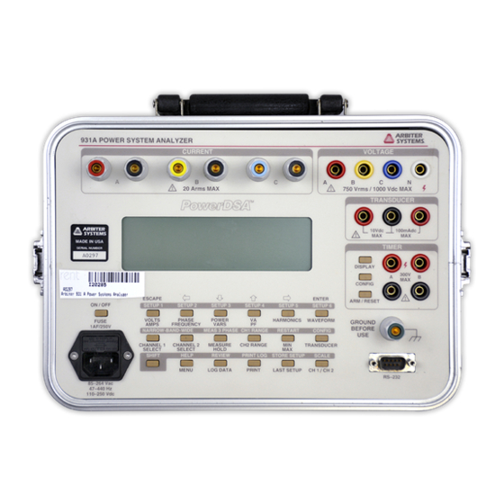
Chapter 2 Functional Description Introduction The following paragraphs provide a brief functional description of some Model 931A components. Figure 2.1 illustrates the front panel. Inputs 2.2.1 Voltage Measure AC or DC voltages through four color-coded insulated banana jacks on the front panel. Labeled A, B, C, and N, each terminal can accept input voltages of up to 750 Vrms or 1000 Vdc. -
Page 20: Model 931A Front Panel
Figure 2.1: Model 931A Front Panel... -
Page 21: Transducer
These inputs share a common return, and accept signals of up to 10 volts DC, or 100 mA DC. The Model 931A can be configured to measure the voltage or current directly, or convert the signals for display of either measured input units or a percentage of full-scale or percent error. -
Page 22: Measurement Method
AC Measurement Configurations Measurement Method The fundamental frequency, of an input signal, is first analyzed by the Model 931A digital signal processing (DSP) algorithms. Using only Channel 1, these measurements require a fairly ”clean” signal. To make accurate measurement of the fundamental frequency, input signal must have less than 30% total harmonic distortion (THD). - Page 23 CH2 and a clean synchronous signal with the desired fundamental frequency to CH1. The Model 931A will lock on to the CH1 signal and the CH2 signal can be analyzed.
-
Page 24: Sampling And Filtering
12.5 Ks/s, allowing accurate measurements at frequencies down to 5 Hz. The record length under these conditions is 655 The Model 931A completes a measurement cycle 2 to 3 times per second. The cycle includes collecting data, processing and displaying results. -
Page 25: Keypad
The Model 931A includes an RS-232C communications port, which allows remote control and command of the instrument using a PC, modem, or terminal. When connecting the Model 931A to a PC, use the supplied null-modem cable. The RS-232C port may also be used to connect a printer to the instrument. -
Page 26: Line Power/Battery Charging
Battery charging occurs whenever power is applied to the Model 931A main power inlet. The internal charger supplies a steady level of power to the instrument, whether powered on or off. If the 931A is powered on, power is split between instrument operation and battery charging. If using the back light, additional power is directed to the instrument, and increases the time to charge the NiMH battery. -
Page 27: Auto-Shutdown Mode
Help ROM version date and the DSP ROM version date. The DSP ROM date is displayed as a decimal number in the format: MMDDYY. As new features are added to the Model 931A these dates are updated. - Page 28 PARTIAL (Calibration Not Disturbed) FULL (All Values Set To Default) Table 2.4: 931A Reset Selection Screen 2.8.2.1 Resetting Procedure NOTE: DO NOT SELECT “FULL” UNLESS YOU INTEND TO COMPLETELY ERASE THE INSTRUMENT CALIBRATION! NOTE: Normally, select “PARTIAL” to restore the instrument to original default conditions.
-
Page 29: Operation
A ground lug, located in the lower right-hand corner of the front panel, is connected to the instrument chassis, and also to the safety ground lead of the AC power connector. When the Model 931A is operated with the power line cord connected, the chassis of the instrument will be connected to the safety ground for the ac outlet. -
Page 30: Voltage Inputs
Safety-insulated banana jacks are used for the connections. Measure voltage between any two of the inputs (e.g., “A” and “N”). Also, the 931A will measure voltage between the input and a synthesized neutral, which is the average of the voltages at inputs A, B, and C. -
Page 31: Transducer Inputs
A transducer can be tested “live” in a circuit, or using an external source. The transducer inputs are connected to the Model 931A voltage or current measurement channels, and the transducer output is connected to the Model 931A transducer measurement input, except for Custom Pulse, which uses the Timer Input. - Page 32 3.3.1.1 Volts/Amps Press the VOLTS/AMPS key to display the amplitude values for the signals routed to Channels 1 and 2. The input multiplexing circuitry determines which input signals are connected to the measurement channels, according to selections made by the operator (see Sections 3.5.1.2 and 3.5.2.2).
- Page 33 Display phase angle as 0 C to 360 C or as 180 C, and a lagging phase angle may also be chosen to be positive or negative by convention. Select your preferred phase convention as described in Section 3.3.1.13, under Menu.
- Page 34 readings are summed once every second, using the real-time clock, to produce Energy readings. 3.3.1.4 VA/PF Press the VA/PF key to display the apparent power and power factor for signals routed to Channels 1 and 2. input multiplexing circuitry determines which input signals are connected to the measurement channels, according to selections made by the operator (refer to Section 3.5.1.2 and 3.5.2.2).
-
Page 35: Phase, Power Factor, And Var Definitions
Figure 3.1: Phase, Power Factor, and VAR Definitions... -
Page 36: Phase, Power Factor, Var Quadrants
Figure 3.2: Phase, Power Factor, VAR Quadrants Phase Convention Quadrant I Quadrant II Quadrant III Quadrant IV CH2 Lagging CH1 (-) for 0 to -90 -90 to -180 +180 to +90 +90 to 0 (+) for 0 to +90 +90 to +180 -180 to -90 -90 to 0 (-) for 0 - 360... - Page 37 3.3.1.5 Harmonics Press the HARMONICS key to view a graphic display of the magnitude of individual harmonics for the signals routed to Channels 1 or 2. The input multiplexing circuitry determines which input signals are connected to the measurement chan- nels, according to selections made by the operator (refer to Sections 3.5.1.2 and 3.5.2.2).
- Page 38 Displayed waveforms correspond to the input signals after they have been digitized and subjected to digital low-pass filtering. The display includes all components of the signal up to 3.05 kHz. The waveform display is normalized to positive going zero crossings of Channel 1 signal fundamentals.
-
Page 39: Channel 2, Ac Voltage Ranges, Vrms
3.3.1.9 Measure Hold Press the MEASURE/HOLD key to stop the measurement process and hold the instantaneous value of each measured parameter. With the exceptions of harmonics, waveform and 3- phase, any display function may be selected during the time that the measurement hold mode is active, and the corresponding values observed. - Page 40 Press the TRANSDUCER key to show measurements taken at the front-panel transducer voltage and current inputs. Config- ure the Model 931A to display the transducer-input magnitude as either the actual measured quantity or as a percentage of full scale. Likewise, display the transducer output level as either the measured quantity or percentage of full scale, or as a percent error (based on the input and output ranges).
- Page 41 Displays a diagnostic message if the memory is full. See Section 3.10 for details of data logging features and controls. For a Model 931A equipped with extended memory, see Section B.3. 3.3.1.15 Print Press the PRINT key to transmit the current measurement data to a printer, modem, or computer connected to the RS-232 port.
-
Page 42: Secondary Functions
CH1/CH2 is useful for checking the amplitude and phase angle ac- curacy of current transformers. Connect the primary in series with a Model 931A current input and set that input to Channel 1. Connect the transformer secondary to another current input and set that input to Channel 2. - Page 43 Press SHIFT, then MEAS 3 PHASE to display the 3-phase mea- surement selection window. MEAS 3 PHASE permits the Model 931A to make sequences of measurements on sets of voltage and current inputs. The measured set of input combinations depends...
-
Page 44: Three-Phase Measurement Selection
To select the appropriate measurement mode, move the cursor to the desired mode and press ENTER. The input pairs shown in parenthesis are those used for the TABULAR display. The Model 931A displays the following display selection menu when you press ENTER: Figure 3.4: Three Phase Display Selection... - Page 45 “Vb” is internally generated using the synthesized neutral circuit, and the accuracy of all results depends on the symmetry of the phase voltages. In all three-phase modes, the Model 931A also measures and displays phase the sequence, “ABC” or “CBA”. (see Figures 3-2 and 3-3). A phase measurement of “Vab to Vac”...
- Page 46 “ABC” Phase Sequence. The waveform display always begins at the zero crossing of the Channel 1 signal. Dashes displayed for the phase sequence indicate that the Model 931A could not measure a valid “Vab to Vac” phase. Phase rotation is determined by measuring “VcnVan”.
- Page 47 Zero-Sequence Currents (I0) and Voltages (V0) are characteristic of unbalanced 3-phase four-wire systems, and correlate to “neutral shift”, where there is a current and potential difference in motor or generator windings with respect to system ground. Zero-Sequence conditions result from unequal phase-to-neutral parameters.
-
Page 48: Three-Phase Displays For An Abc System
Tabular with Power Vector Diagram Voltage and Current Sequence Waveform Figure 3.6: Three-Phase Displays for an ABC System... -
Page 49: Three-Phase Displays For A Cba System
Tabular with Power Vector Diagram Voltage and Current Sequence Waveform Figure 3.7: Three-Phase Displays for a CBA System... - Page 50 3.3.2.9 System Connections Figure 3.8: 1-Phase, 2-Wire, 1-Element Connections Figure 3.9: 1-Phase, 3-Wire, 2-Element Connections...
- Page 51 Figure 3.10: 3-Phase, 3-Wire, 2-Element Connections Figure 3.11: 3-Phase, 4-Wire, 2.5-Element Connections...
- Page 52 Figure 3.12: 3-Phase, 4-Wire, 3-Element Connections...
-
Page 53: Channel 1, Ac Voltage Ranges, Vrms
3.3.2.10 CH1 Range Press the CH1 RANGE key to select the operating voltage or current range for Channel 1. The ranges are only approximate and vary from unit to unit. Press SHIFT then the CH1 RANGE key to view a menu showing a selection of auto range or a fixed range. - Page 54 Model 931A can be set to automatically calculate and display transducer error as percent of full scale, when the same input signal is applied to the transducer under test and the Model 931A. Any calibrator or load box with source may be used, or transducers may be calibrated in-circuit.
- Page 55 For instructions on recalling instrument setups, see Section 3.3.2.2. 3.3.2.17 Scale Use the SCALE key to apply individual Scale Factors to each AC measurement input function. Scale Factor corrections can adapt the Model 931A for use with current or potential transformers.
- Page 56 For example, a magnitude scale factor of 100, with 10 volts applied to the Model 931A input, displays 1000 volts. Therefore, if the Model 931A was used to measure the voltage at the output of a 100:1 PT, and the magnitude scale factor was set to 100, the display would show the actual voltage value present at the PT input (compensating for the 100:1 reduction of the PT).
-
Page 57: Data Entry Functions
left arrow keys. Finally, use the up and down arrow keys to change the numerical digit, or decimal point, and press ENTER. After the changing the PT and CT values, move the cursor to PT/CT ON, and press ENTER. When done, this applies the new scale factors for PT and CT to every input, and blocks out the individual scale factors shown for Vxy and Ix. -
Page 58: Timer Control Functions
3.3.3.2 Left Arrow Use the left arrow key to move the display cursor to the left. The cursor movement function associated with this key is automatically enabled when required. After making a menu selection, this key will return to its primary function. - Page 59 3.3.4.1 Display Use the DISPLAY key to view the main display for the timer; this includes the time measurement, the timer function and trigger modes. An example is shown below. In the main timer display, FUNCTION shows the parameter that the timer is configured to measure.
-
Page 60: Front Panel Display
The following sections provide instructions for performing measure- ments of parameters within this group. 3.5.1 AC Voltage Measurement The Model 931A can measure and display AC voltages of up to 750 Vrms. 3.5.1.1 Input Connections Four inputs, labeled “A”, “B”, “C”, and “N” are available for measuring AC voltage, and each uses identical circuitry. - Page 61 NOTE: The Model 931A does not provide for measurement of voltage between voltage inputs and chassis ground lug. Make all measurements between two (or more) of the voltage inputs. The ground lug is included for safety purposes only, especially during battery operation. See Sec- tion 3.2.1.
-
Page 62: Ac Current Measurement
3.5.2 AC Current Measurement The Model 931A can directly measure and display AC currents of up to 20 Arms. It can measure higher currents using a current transformer (CT) and with direct readout using the scaling feature (see “Scale” in Section 3.3.2.17). - Page 63 Channel 2. The display indicates the general measurement bandwidth (i.e. Wide- Band) near the lower left-hand corner. The Model 931A uses either wide- band or narrow-band mode to measure and display AC voltage. Select measurement bandwidth by pressing SHIFT, followed by either NARROW-BAND or BAND-WIDE.
-
Page 64: Dc Voltage Measurement
3.5.3 DC Voltage Measurement The Model 931A can directly measure and display DC voltages of up to 1000 Vdc. 3.5.3.1 Input Connections The Model 931A provides four connectors for measuring dc voltage. Labeled “A”, “B”, “C”, and “N”, all four inputs use identical circuitry. -
Page 65: Frequency Measurement
Frequency measurements. 3.5.4.1 Input Connections The Model 931A can measure the frequency of AC voltages or currents connected only on Channel 1. Make connections in the same manner as for magnitude measurements (see Section 3.2.2 for AC voltages, and Section 3.2.3 for AC currents). -
Page 66: Harmonic Measurement
3.5.5 Harmonic Measurement The Model 931A can measure harmonic content up to the 50th harmonic for fundamental signals of 50 or 60 Hz. Use either Channel 1 or 2 to measure harmonics, but on only one channel at a time. - Page 67 The top line of text shows THD and K-factor, which relate to the overall input signal, and do not change when the cursor is moved. The Model 931A analyzes harmonics by first determining the AC fundamental and the DC components of the signal. It then removes them algebraically from the digitized waveform.
-
Page 68: Combined Measurements
Channel 1, and the current signal to Channel 2. Since the voltage in a power system is usually more stable and less distorted than the current, the Model 931A uses Channel 1 as a reference for phase measurements. Both a voltage and current input signal are required to measure all power quantities. - Page 69 3.6.1.1 Configuring the Channels NOTE: See Section 3.2.2 and 3.2.3 for input connection description. Connect the signals to the appropriate input terminals and configure the measurement channel by pressing CHANNEL 1 SELECT and CHAN- NEL 2 SELECT. See channel selection screens below. 3.6.1.2 Performing the Measurement Press the PHASE/FREQUENCY key to produce a display similar to the...
-
Page 70: Active Power - Reactive Power
3.6.2 Active Power – Reactive Power The Model 931A can measure the active power (rms watts) and reactive power (vars) from the combination of an AC voltage routed to measure- ment Channel 1 and an AC current routed to Channel 2. - Page 71 Pressing POWER/VARS will produce a display similar to the one shown below: The large number at the top of the display shows the active power measured. The lower number shows the reactive power. Also, the display indicates if the Model 931A is making wide-band or narrow-band measurements.
-
Page 72: Apparent Power - Power Factor
θ) 3.6.3 Apparent Power – Power Factor The Model 931A can measure the apparent power (volt-amps, or VA) and power factor from the combination of an AC voltage routed to Channel 1 and an AC current routed to Channel 2. - Page 73 Arrows form the cursor, which highlight one of the selections. Press the arrow keys to locate the measurement value. For example, using the arrow keys move the cursor to “Van” to measure an AC voltage between inputs “A” and “N”. Press ENTER to confirm selection. Press CHANNEL 2 SELECT to configure Channel 2 in the same way as for channel 1.
-
Page 74: Waveform Display
Timer Measurements The Model 931A includes a timer for measuring events such as relay contact timing. The timer has two channels, which are optically isolated from the instrument common and from each other. Both inputs can accept various triggering inputs, including: ˆ... -
Page 75: Connecting The Inputs
3.7.1 Connecting the Inputs The two timer inputs are labeled “A” and “B”, with one black terminal and one red terminal for each input. Apply AC or DC input signals to either channel without regard to polarity. NOTE: In contact closure or opening mode, external voltage should not be applied to the inputs;... - Page 76 ˆ “Rate of A” causes the timer to display the rate of a valid triggering event at the “A” input. NOTE: The timer triggers without regard to polarity. If selecting DC Applied as the trigger and a symmetric signal of greater than 6 Vpp is applied, the rate displayed will be double the actual frequency.
- Page 77 3.7.2.3 Hold Mode on Stop Select Hold Mode On Stop from the Timer Configuration Menu and press ENTER to view the following sub-menu: Use this sub-menu to leave the instrument in the measure hold mode at the end of a timer cycle. Select Disable to continue normal operation, with all measured param- eters being updated continuously.
-
Page 78: Timer Measurement Categories
“B” are exactly the same as those for input “A”. See Section 3.7.2.4. 3.7.3 Timer Measurement Categories All measurements performed by the timer section of the Model 931A can be classified as either time or count measurements. The following paragraphs describe both categories. - Page 79 Press ARM/RESET to clear the timer data and reset the display to zero. Pressing ARM/RESET also switches the timer from the Stopped to Standby. The Model 931A displays the timer-state below the word “Timer.” A blank status indicator signifies the instrument is in Standby. 3.7.3.2...
-
Page 80: Transducer Testing
Testing transducers with the Model 931A is straightforward using an external source, such as a calibrator or source and load box. Also perform live, in-circuit tests. Prior to starting a transducer test the Model 931A automatically makes a self-calibration. Use the main measurement inputs to precisely monitor the transducer input values. - Page 81 Menu selections are described below and help explain how these selections apply when performing Transducer Testing. ˆ “1Ph 2Wire 1E” sets the Model 931A to measure values in a single- phase circuit, having a hot wire and a neutral wire. Since sequential...
- Page 82 “C”). To create voltage “b”, connect the “B” voltage input to the “N” voltage input. ˆ “3Ph 4 Wire 3E” sets the Model 931A to measure values on a 3-phase Y circuit, for comparison to a 3-element transducer. See Figure 3.17. Use internal operating software definitions for inputs as follows: “VanIa”;...
- Page 83 See Section 3.6.3 for a description of apparent power measurements. ˆ “Amps” sets the Model 931A to make current measurements on the predefined input routed to Channel 2 and compares it to a current transducer. Route input to measurement Channels 1 and 2 if only a current signal is available.
- Page 84 ˆ Custom mA allows the user to enter a current range within the limits of 0 to 100 milliamperes DC. ˆ Custom Pulse allows the user to setup the Model 931A to accept a calibrated pulse from the transducer that is proportional to the measured transducer value.
- Page 85 ˆ “Measured Quantity” displays the value present at the Model 931A measurement inputs in actual measurement units (e.g. volts, amps). ˆ “Percent Full Scale” displays the value present at the Model 931A measurement inputs as a percentage of full-scale. Full-scale is defined by the lower and the upper limit of the currently selected input range (see Section 3.8.1.3 for a description of Input Ranges).
-
Page 86: Connecting The Inputs
3.8.2 Connecting the Inputs If needed, use the main measurement inputs on the Model 931A as the input for transducer tests at any value up to their rated maximum (see Specifications in Section 4). Connect the voltage and current measurement inputs according to the type of transducer being tested. - Page 87 Figure 3.14: 1-Phase, 2-Wire, 1-Element Transducer Test...
- Page 88 Figure 3.15: 1-Phase, 3-Wire, 2-Element Transducer Test...
- Page 89 Figure 3.16: 3-Phase, 4-Wire, 2.5-Element Transducer Test...
- Page 90 Figure 3.17: 3-Phase, 4-Wire, 3-Element Transducer Test...
-
Page 91: Connecting The Outputs
If testing transducers with voltage outputs, connect them between the transducer voltage input (left) and common (middle). NOTE: Be certain to configure the Model 931A to accept the type of transducer signal and range, whether voltage or current output. Sec- tion 3.8.1.4 describes available Output Ranges. - Page 92 Most transducers with contact (or pulse) outputs use either an electrome- chanical or a solid-state relay. If the transducer has an electromechanical relay at the output, it is important to use the Debounce feature on the Model 931A. Otherwise, do not use it. 3.8.5.3 Configuring in the Transducer Menu Press SHIFT then CONFIG to access the Transducer Configuration menu.
- Page 93 6. Display Output As – select either Measured Quantity or Percent Error. Although the menu choices include Percent Full Scale, only Measured Quantity and Percent Error pertain to Custom Pulse. The sample Transducer Configuration Menu shown below illustrates settings for a different transducer using the “Rate of A” Function instead of “Time A to X Counts.”...
- Page 94 Contact Closures < 1/second The best selection for contact closures < 1/second is Time A For X Counts. This function allows the Model 931A to measure transducers with contact outputs that are relatively slow – in the range of seconds between pulses.
- Page 95 % error. It does this by measuring the overall time for multiple contacts (defined by X) and divides that time by the number of contact closures. At the end of a test, the Model 931A displays and holds the Input and Output values until pressing ARM/RESET, which begins a new test.
-
Page 96: Performing A Test
Connect the transducer pulse output to the Model 931A Timer A input terminals with suitable cables. The Custom Pulse function works only with Timer Input A. Connect the transducer and the Model 931A to a source providing the required output levels for testing the transducer. Refer to Figure 3.18 for an illustration of using a power transducer. - Page 97 FIG (transducer) or CONFIG (timer) to change the measurement settings. After re-configuring the test parameters, press the TRANS- DUCER key and the Model 931A is ready for another test. To start the next test, press the ARM/RESET key twice. 3.8.6.2 For Contact Closures >...
- Page 98 The screen below illustrates the Model 931A measuring a transducer using “Rate of A.” 3. Using the “Rate of A” Function, the Model 931A should continually update the measurement values. The Model 931A also cycles between each measured phase indicated in the lower left corner of the display.
- Page 99 Figure 3.18: 3-Phase, 4-Wire, 3-Element Custom Pulse Transducer Test...
-
Page 100: Using External Pt's And Ct's
Using External PT’s and CT’s Use an external current transformer (CT) and potential transformer (PT) to extend the measurement range of the Model 931A. If used, however, do not exceed the input range of the instrument (refer to Chapter 4, Specifica- tions). -
Page 101: Reviewing Data
ˆ 3-phase data includes all the data presently on the 3-phase display.hen the Model 931A captures a data record, it displays a momentary message in the lower right-hand corner. The message confirms that the data was saved and shows the assigned record number. -
Page 102: Erasing Logged Data
(using the LOG DATA key). Most printed or exported data records are stamped with the date and time, according to the real-time clock in the Model 931A. Each data record also includes a record number, referred to as the ”log data number.” Data that is printed or exported directly during measurement has a log data number of zero. -
Page 103: Ascii Format
Tera Term Pro. The procedure for capturing bitmap files is as follows: 1. Press the MENU key > Print Selections and choose Bitmap (Xmo- dem Transfer). 2. Connect the Model 931A to the host computer, using a 9-pin RS- 232C cable. Make sure that the serial communication parame-... -
Page 104: Spreadsheet
The type of exported data depends on which operating mode the Model 931A is set for at the time the PRINT key was pressed. Firmware outputs all spreadsheet data as ASCII text. The following paragraphs provide a breakdown of the different data types, and their corresponding formats. - Page 105 Log Data #: A number assigned to the data record. the data was stored prior to print/export, this number will correspond to the record number assigned when stored. If the data is printed or exported directly, this number will always be zero.
- Page 106 Channels 1 and 2. 3.11.5.2 3-Phase Data The Model 931A exports 3-phase data when executing the print operation. This occurs in one of the 3-phase tabular display operating modes. The 3-phase data is exported with the following format: log data #, date, time, min/max/normal, 3 phase mode,...
- Page 107 Time: A decimal fraction of 1, corresponding to the time of day, which is the standard format for time in spreadsheet applications. This number is determined by the formula: n=S/86400, where: S = number of seconds elapsed since midnight. Min, Max, Aver- Denotes whether the data corresponds to the age, Normal: minimum-recorded values, maximum-recorded...
- Page 108 C-Phase power factor. Lead/Lag 3.11.5.3 Timer Data The Model 931A exports timer data when executing the print operation. This occurs while performing measurements or reviewing stored data in the timer mode of operation. Timer data is exported with the following format:...
- Page 109 Log Data #: A number assigned to the data record. the data was stored prior to print/export, this number will correspond to the record number assigned when stored. If the data is printed or exported directly, this number will always be zero.
- Page 110 3.11.5.4 Transducer Data The Model 931A exports transducer data when executing the print operation. This occurs while performing measurements or reviewing stored data in the transducer mode of operation. Transducer data is exported with the following format: log data #, date, time, input value, input units, output value, output units Log Data #: A number assigned to the data record.
- Page 111 3.11.5.5 Harmonic Data The Model 931A exports harmonic data when the print operation is executed. This occurs while performing measurements in the harmonic display mode, or reviewing stored data while in that mode. Harmonic data differs from most of the other data types, in that it is a tabular format consisting of 49 records.
- Page 112 3.11.5.6 Waveform Data The Model 931A will export waveform data while the print operation is executed. This occurs when performing measurements in the waveform display mode, or reviewing stored data while in that mode. Waveform data is tabular format and similar to harmonic data. It consists of 240 records, which correspond to points on the waveforms for measurement channels 1 and 2.
-
Page 113: Initiating Printing / Exporting
Date: An integer, corresponding to the date, which is the standard format for dates in spreadsheet applications. The integer for the date is deter- mined from the following: 1/1/1600 = -109,571 12/30/1899 = 0 1/1/95 = 34700 12/31/3199 = 474,816 Time: A decimal fraction of 1, corresponding to the time of day, which is the standard format for... -
Page 115: Specifications
Chapter 4 Specifications Inputs 4.1.1 Voltage Inputs: Four: A, B, C and N Phase to Phase Phase to Neutral Phase to Synthesized Neutral Input Range: 750 Vrms (under range to 200 mV) 1000 Vdc (under range to 300 mV) Impedance: 1 megohm Leakage: <... -
Page 116: Timer
Transducer, continued Range: 10 Vdc 100 mAdc Input 100 kΩ (voltage) Impedance: Burden: 20 Ω nominal, including PTC resettable fuse 1 kΩ for 1 mA 4.1.4 Timer Inputs: Maximum: 300 Vrms or DC Isolation: 300 Vrms Threshold: Contact open 2.9 Volts Threshold: Contact closed 2.6 Volts Source Impedance... -
Page 117: Frequency
4.2.3 Frequency Input: Channel 1 Fundamental 500 Hz (voltage under range to 5 Hz) Range: Accuracy: 0.005% of reading 4.2.4 Timer Inputs: Two, voltage or dry contact Input Ranges: 4 to 300 Vdc 20 to 300 Vrms Isolation: 300 Vrms (each channel) optical Range: 0.0001 to 9999.9 seconds 0.01 to 999999 cycles... -
Page 118: General Specifications
General Specifications 4.3.1 Measurement Bandwidth Wideband Mode: 3.05 kHz. Narrowband Mode: 500 Hz, fundamental only (deter- mined by DSP) 4.3.2 Memory Type: Non-volatile (battery-backed RAM) Data stored: User setups, measurement results; Time and date tagged. 4.3.3 Display Type: Supertwist Liquid Crystal. Resolution: 240(h) by 64(v) pixels Dimensions:... -
Page 119: Input Power
4.3.6 Input Power Line Voltage: 264 Vac (47 – 440 Hz), 250 Vdc. Power: 15 W / 15 VA, max. Battery: Internal NiMH, 7.2 V, 6.5 Ah, 8 hours of operation. Charger: Automatic, monitors ∆T /∆t, ∆V /∆t, and time. Charge Time: 8 hours. -
Page 121: A Rs-232C Commands
The following appendix contains a listing of commands, definitions and examples that may be used to control and communicate with the Model 931A via the RS-232C serial interface. Commands that request information from the instrument return either current or previously logged data. Numeric data is returned as an ASCII string of numeric characters, with leading sign and embedded decimal point as needed. -
Page 122: Serial Port Examples
Serial Port Examples This section contains examples of controlling the Model 931A with serial commands from a computer, or terminal, to access its various features. In each example the left-hand column gives the example command. The right-hand column gives a brief description of the result after entering the command. -
Page 123: Command Summary
Command Summary A.3.1 Battery Charging Status (BAT) Command: Returns Battery and charging status. Return Value Meaning Nothing Low Battery Charging A.3.2 Backlight Set (BLT) Command: #BLT Controls the front panel LCD backlight. Response Backlight OFF Backlight ON Backlight AUTO. The backlight remains on for approximately 20 seconds after the last keystroke. -
Page 124: Ratio Ch1/Ch2 (Ccr)
Ratio CH1/CH2 (CCR) Command: Displays the measured results (on the Model 931A) as the magnitude and phase angle of the ratio of Channel 1 divided by Channel 2. Depending on the input signals selected, the display units for magnitude will be ohms, mhos, or p/u. -
Page 125: Calibrate Input (Cin)
A.3.6 Calibrate Input (CIN) Command: in#,gain#,ph/off#,s/r#CIN Sets or returns the magnitude and phase calibration constants for the individual inputs. Config Config Config Config gain# Corrected gain = uncorrected gain (1 + gain# 1000) Ph/off# Corrected phase = uncorrected phase + (ph/off# freq) Offset = ph/off# 1000 (DC) s/r#... -
Page 126: Daylight Saving Time, Set (Day)
(Transducer Configuration, continued) int# Input Type infs# Input Full Scale Volts 0 to 9999.9 Amps Phase inll# Input Lower Limit Frequency 0 to 9999.9 Power Vars dco# DC Output Volt Amps Volts Power Factor Millamperes ofs# Output Full Scale (DC) Display input as: 0 to 10 VDC or... -
Page 127: Data Dump, Bitmapped (Ddb)
A.3.10 Data Dump, Bitmapped (DDB) Command: Screen dump in bitmap format Response: Enables XMODEM binary file-transfer protocol-CRC only. May be sent by host computer prior to initiating transfer request. Sus- pends normal instrument operation pending file transfer. The file consists of 2110 8-bit bytes including 62 bytes of header information and 2048 bytes of graphics data. -
Page 128: Timer Calibrate (Ftm)
Action (or # missing) – return frequency immediately Return only if there is a new reading A.3.14 Timer Calibrate (FTM) Command: c#,s/r#FTM Sets or returns the calibration constant to correct the timer time and frequency reference. 1 + (c# 1,000,000) multiply the time measurements made by the timer. -
Page 129: Harmonic Phase Angle, Return (Hph)
A.3.17 Harmonic Phase Angle, Return (HPH) Command: harm#,ch#HPH Returns individual harmonic phase angle for the selected channel. Set the unit to measure harmonics, on the selected channel using the HAR command, prior to issuing this command. harm# To select 2–50 Harmonic number (2 through 50) THD (Total harmonic distortion) Channel 1... -
Page 130: Magnitude (Channel), Return (Mag)
A.3.21 Magnitude (Channel), Return (MAG) Command: ch#,Q#MAG Returns the selected channel magnitude. Use the Channel Select (#, ch#CHS) input select command prior to using this command. In 3-phase mode, MAG returns the average of the measured magnitudes (RMS, mag, or DC). Selection Selection Channel 1... -
Page 131: Overload Status (Ovd)
A.3.25 Overload Status (OVD) Command: Returns: Value Status No overload Channel 1 overload Channel 2 overload Both Channels 1 and 2 overload A.3.26 Phase/Frequency Display (P F) Command: Displays Channel 1 frequency and the phase angle of Channel 2 relative to Channel 1. -
Page 132: Phase Mode, Set (Phm)
A.3.29 Phase Mode, Set (PHM) Command: mdPHM Starts single or 3 phase measurement mode. Mode Mode 1ph, 2 wire, single phase Tabular Display (with Power) 1ph, 3 wire, 2 element, Tabular Display split phase (with Energy) 3ph, 3 wire, 2 element Vector Diagram 3ph, 3 wire, 3 element Voltage &... -
Page 133: Range Hold, Set (Rhd)
RS-232C using the LOG command. Use 0RLD to clear all logged data. When issuing this command, the specified record is written to the Model 931A display, overwriting current measurement data and placing the Model 931A in Measurement Hold Mode. Use 0MHD to release Measurement Hold Mode, and resume measurement. -
Page 134: Transducer Channel (Scc)
A.3.36 Transducer Channel (SCC) Command: ref#,r1#,r2#,s/r#SCC Includes DC Reference, and Shunt Resistance Values – Set or Return (see Note 1 on page 105). Sets or returns the transducer channel DC reference and shunt resistance values as follows: ref# Reference voltage in volts 9 ohm shunt resistance in ohms. -
Page 135: Scale On/Off (Soo)
#3 = 1 through 12, month #4 = 1 through 31, day of month #5 = 0 through 23, hour of day #6 = 0 through 59, minute of hour #7 = 0 through 59, seconds of minute A.3.39 Scale On/Off (SOO) Command: #SOO Globally activates or deactivates input scale corrections. -
Page 136: Range, Set (Srg)
Add 4 to each of the numbers above to disable the Lead/Lag indication on the Power Factor Display. A.3.42 Range, Set (SRG) Command: rng#,ch#SRG Used to set the analog input range. After the range is set, puts the selected channel into Range-Hold Mode. Use the ch#RRH command to release Range-Hold. -
Page 137: Store Setup (Sst)
Config. Config. Config. Vab,Vba Vcn, Vcs Vbc, Vcb Vca, Vac Ia, In Van, Vb, Vas Vbn, Vbs Magnitude correction 0 to 999999 Phase angle correction 0 to 359.9 s/r#: 0 to enter scale value; 1 to return scale value. A.3.44 Store Setup (SST) Command: #SST... -
Page 138: Timer Configuration, Set Or Return (Tcf)
Sets Date and Time for the real-time clock. Time is always set to standard time. Use the #DAY command to adjust for daylight saving time. yyyy Year Month Hour Minute Second A.3.49 Timer Configuration, Set or Return (TCF) Command: d#,f#,h#,at#,bt#,s/r#TCF Returns or sets the parameters necessary for timer operation. -
Page 139: Timer Display (Tim)
Command: Displays the Timer results in seconds, cycles, counts, or Hertz on the Model 931A, according to the timer function. The Timer must be configured using the TCF command. Once the Timer has been configured, it may be armed using the TAM command. Displays the accumulated time after a valid trigger condition. -
Page 140: Va/Pf Display (V P)
A.3.57 VA/PF Display (V P) Command: #V P Result (or # absent) Displays the apparent power and power factor of the signals on Channels 1 and 2. Channel 1 must be set to measure AC voltage and Channel 2 AC current. VA hours A.3.58 Volt-Amps, Return (VAM) -
Page 141: Waveform Display (Wav)
A.3.61 Waveform Display (WAV) Command: ch#WAV Enables the waveform display of channel 1 and channel 2. To select Channel 1 Channel 2 Both Channel 1 and 2 A.3.62 Bandwidth Wide, Set (WIB) Command: Changes the measurement mode for amplitude and power quantities to wide-band including all harmonics up to 3.05 kHz. -
Page 143: B Optional Accessories
Connect a high-current source as follows: 1. Slip the transformer output spade lugs into one set of the Model 931A current input binding posts (A, B, or C), and tighten securely. 2. Connect the high-current source to the 5/16-18 bolts at the top of the transformer, using a 1/2”... -
Page 144: Current Display
B.1.3 Current Display To display the input current reading directly on the Model 931A, press SHIFT, then SCALE and set the CT value to “20,” and set PT/CT to “ON.” Refer to Section 3.3.2.17 for details on setting Scale Factors. -
Page 145: Extended Memory
LOG DATA key in the same manner as with standard memory. Data recorded with extended memory is identical to that stored when the Model 931A is equipped with standard memory, however the record structure is more elaborate. Additionally, users can customize recorded data with the Custom function. -
Page 146: Data Organization
Normal Each record stored as normal data contains enough information to com- pletely restore the Model 931A to its state when the record was logged. The type of data stored depends on the active instrument display at the time the record was logged. There are four types of normal data: ˆ... - Page 147 Each record in the same data file contains the same set of parameters. Changing the data type after logging data causes the Model 931A to create a new file, with its own header and associated set of records. Even with custom record definitions, new files with record structures are started when pressing the log data key after changing the display.
-
Page 148: Computing The Number Of Files And Records
B.3.2 Computing the Number of Files and Records With the 16-megabyte, extended-memory option installed, the Model 931A is limited to a maximum of 20 files. Beyond that, it is only the size and the number of records that limit filling up the entire 16 megabytes. -
Page 149: Log Data Triggering
23 hours, 59 minutes and 59 seconds. This setting represents the interval between each data recording. The Model 931A will continue to log data at the chosen time interval for as long as the clock time is between the start and stop times, and the stop time is later than the start time. -
Page 150: Front Panel Operation
B.3.4 Front Panel Operation If the Model 931A is equipped with the extended memory option, the first sign-on display will show “16 Mbyte Log Memory Card Installed.” “Auto- Log Setup” has been added as a selection item on the main menu. Press the MENU key and select “Auto-Log Setup”... -
Page 151: Remote Operation
Select 0 to clear all the data in the extended memory. Percentage numbers following LOG SPACE and AUX MEM show the amount of memory available. The LOG SPACE is where the headers for each file are stored. As the number of files increases the amount of LOG SPACE will decrease. - Page 152 #1=0 manual trigger from front panel LOG key or RS232 LOG command. #1=1 trigger from timer A. #1=2 auto trigger with interval set by #2. #2=1 to 86400 auto log store trigger interval in seconds. #3=32 bit data descriptor entered as decimal number. If 7 numbers are present: #1=0 #2...#7 = autolog start time.
-
Page 153: Review Of Logged Data
1,1997,1,1,0,0,0SL0: Sets the autolog stop time to January 1, 1997 at midnight. Stop time must be later than start time. The configuration of custom data is contained in a 32-bit word. Each bit in this word refers to a data parameter. The custom data Table B.1 lists each of the available parameters along with their assigned ID bit and decimal weight. -
Page 154: Trigger Remote Data Logging
B.3.7.1 Examples using RLD Command Command Action Returns a list of the logged data files, as shown in the following example of a returned message. LOG SPACE 87% AUX MEM 98% FILES 6 9 Dec 1996 13:37:54 9 Waveform 9 Dec 1996 13:38:05 4 Harmonic 9 Dec 1996 13:38:37 15 Custom... -
Page 155: C Ce Mark Certification
Date of Issue: October 1, 2008 Directives: 89/336/EEC Electromagnetic Compatibility 73/23/ EEC Low Voltage Safety Model Number: 931A Power System Analyzer Manufacturer: Arbiter Systems, Inc. 1324 Vendels Circle, Suite 121 Paso Robles, CA 93446 Harmonized EN55011 Class A, Radiated and Conducted... - Page 156 Index AC measurement configurations, 6 life, 103 accessories, 2, 127 life with backlight, 44 accuracy line power, 10 low indicator, 10 400 Amp CT, 127 checking amplitude and phase, power, 1 RAM, 102 fast mode, slow mode, 8 harmonic measurement, 21 cable measurements, 100 null modem, 2, 9...
- Page 157 3-phase, 90 FFT, 7, 21, 51 custom, 131 frequency range, 6 custom table, 131 front panel entry, 41 connections, 13 display, 44 harmonic string, 95 drawing, 4 log triggering, 133 keys, 15 logging, 25, 133 normal, 130 ground, chassis review, 38 current input isolation, 3 standard, 88 current inputs isolated, 46...
- Page 158 voltage terminals, 3 Transducer, 24 issuance, ii Up Arrow, 42 VA/PF, 18 K-Factor, 21, 51, 96 Volts/Amps, 16 keypad, 9, 102 Waveform, 21 keys, 13 Wide Band, 27 Arm/Reset, 43 CH1 Range, 37 logging data, 84 Ch1/Ch2 (ratio), 26 CH2 Range, 23 main functions, 15 Harmonics, 21 Channel 1 Select, 22...
- Page 159 8 records, number of, 132 RRH, release range hold, 117 RST, min/max restart, 117 remote operation, 135 SCC, transducer channel, 118 resetting the 931A, 11 SER, serial number, 118 restart key, 37 reviewing data, 38 SLO, flash log, 118 RS-232C...
- Page 160 SPD, DSP speed, 119 display, 102 SPH, phase pref. set, 119 environment, 102 SRG, range set, 120 input power, 103 SSC, scale factors, 120 keypad, 102 SST, store setup, 121 measurement BW, 102 SUP, recall setup, 121 memory, 102 TAM, arm timer, 121 serial port, 103 TCF, configure timer, 122 specifications, input, 99...
- Page 161 display, 43 version display choices, 60 manual, v hold mode, 61 viewing sign-on message, 11 measurement categories, 62 warranty, iii measurements, 58 waveform ratings, 5, 100 display, 58 select function, 59 viewing, 21 states, 63 wide-band mode, 7, 16–18, 27, 46 time measurements, 63 Trigger A, 61 Trigger B, 62...
Need help?
Do you have a question about the 931A and is the answer not in the manual?
Questions and answers