DragonWave Horizon COMPACT Plus Product Manual
Compact out-door-unit
Hide thumbs
Also See for Horizon COMPACT Plus:
- Quick reference manual (2 pages) ,
- Product manual (200 pages)

Related Manuals for DragonWave Horizon COMPACT Plus


Summary of Contents for DragonWave Horizon COMPACT Plus
- Page 1 Horizon COMPACT Plus Wireless Ethernet Release 1.0.1 Product Manual - Volume 1 Installation, Basic Configuration and Alignment Version 1.2...
- Page 3 NOTICE This document contains confidential information, which is proprietary to DragonWave. No part of its contents can be used, copied, disclosed, or conveyed to any party in any manner whatsoever without prior written permission from DragonWave Inc. Copyright © 2000 - 2012 DragonWave Inc.
-
Page 4: Table Of Contents
5.2.2 ..........30 LTERNATE OWER PTION DAPTER ABLE ..................32 NITIAL ONFIGURATION ....................... 32 ECURE ANAGEMENT CCESS ..........................32 SING ELNET 6.2.1 ..........................32 OGGING ON Wireless Ethernet Product User Manual – Volume 1 Horizon Compact Plus Release 1.0.1... - Page 5 ..............70 ONFIGURATION ACKUP AND ESTORE 14.1 ....................70 YSTEM ONFIGURATION ACKUP 14.2 ....................70 YSTEM ONFIGURATION ESTORE 14.3 ......................71 CCOUNTS ACKUP 14.4 ......................71 CCOUNTS ESTORE Wireless Ethernet Product User Manual – Volume 1 Horizon Compact Plus Release 1.0.1...
- Page 6 ULTIPLE YSTEMS A – CLI C ................... 74 PPENDIX OMMAND B – S ................80 PPENDIX AFETY NFORMATION C - R ........... 84 PPENDIX EGULATORY OMPLIANCE NFORMATION Wireless Ethernet Product User Manual – Volume 1 Horizon Compact Plus Release 1.0.1...
- Page 7 IGURE OUNTING BRACKET WITH FINE ADJUSTMENT BOLTS 10-2 V ......55 IGURE OLTMETER CONNECTIONS TO FIELD STRENGTH MONITORING CONNECTOR 10-3 M ......................57 IGURE AIN AND OBES Wireless Ethernet Product User Manual – Volume 1 Horizon Compact Plus Release 1.0.1...
- Page 8 AIN LOBE AND SIDE LOBES DISTANCE OF APPROXIMATELY 11-1 A ................. 61 IGURE LIGNING YSTEMS SING OCAL ANDMARKS 11-2 U ............61 IGURE SING OMPASS EARINGS TO LIGN YSTEMS Wireless Ethernet Product User Manual – Volume 1 Horizon Compact Plus Release 1.0.1...
- Page 9 PPROXIMATE SIZE OF BEAM AT DESTINATION 10-3 D ................58 ABLE EGREES PER EVOLUTION OF DJUSTMENT 11-1 T ................... 60 ABLE ORQUE PECIFICATIONS FOR NTENNAS 15-1 S ....................... 72 ABLE OFTWARE PGRADE Wireless Ethernet Product User Manual – Volume 1 Horizon Compact Plus Release 1.0.1...
-
Page 11: User Manuals
Volume 1 Volume 3 – contains a complete list of the frequency tables associated with the radio bands supported, and soon to be supported, by the Horizon Compact Plus Volume 4 - contains configuration details relating to industry standard networking features. - Page 12 DragonWave Inc. This page is left blank intentionally Wireless Ethernet Product User Manual – Volume 1 Horizon Compact Plus Release 1.0.1...
-
Page 13: Introduction Toh
High Capacity Native Ethernet Wireless Gigabit Ethernet Designed as an Ethernet platform from the ground up, the DragonWave Horizon Compact Plus meets the critical needs demanded by carrier class customers delivering a wireless GigE/100bT connection of up to 800 Mbps full duplex over licensed or unlicensed frequency allocations. -
Page 14: Applications
Horizon Compact Plus enables rapid network expansion with remote scalability from 10 Mbps to 800 Mbps. With Horizon Compact Plus the radio and modem are integrated into a single all-outdoor element attached directly to the antenna, allowing simple integration and eliminating any impact on the 4G base station footprint. -
Page 15: Technical Specifications
Introduction to Horizon Compact Plus Technical Specifications Frequencies Power 6 GHz FCC/IC/ETSI/ITU Input -40.5 VDC to -56 VDC, isolated 7 GHz ETSI/ITU/MX Optional Adapter 110/240 VAC 8 GHz ETSI/ITU Consumption (GHz/Watts) 11 GHz FCC/IC/ETSI/ITU 13 GHz ETSI/AUS/NZ/ITU 6/55, 7/80, 8/80, 13/47,15/47, 18/49, 23/48, 38/43, 60/37... - Page 16 DragonWave Inc. This page left blank intentionally Wireless Ethernet Product User Manual – Volume 1 Horizon Compact Plus Release 1.0.1...
-
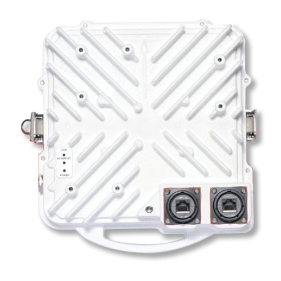
Page 17: 3.0 Physical Description
3.0 Physical Description Horizon Compact Plus is an integrated Ethernet modem and microwave radio transceiver, housed in a rugged weatherproof housing. It is provided with two weatherproof port connectors, Port 1 and Port 2. Port 1 can be configured as a single copper 10/100/1000 Base-t data port (GigE), or as two 10/100 Base- t data ports (port 1 and port 4). - Page 18 3) Alternate Fast: RED ON for 0.5sec, OFF for 0.5sec, GREEN ON for 0.5sec, OFF for 0.5sec. 4) Alternate Slow: RED ON for 2sec, OFF for 2sec, GREEN ON for 2sec, OFF for 2sec. Wireless Ethernet Product User Manual – Volume 1 Horizon Compact Plus Release 1.0.1...
-
Page 19: Ethernet And Power
The power feed wires (see Table 3-2 for recommended gauge) are spliced into the adapter cable using weatherproof tap connectors. The power feed and Port 2 Ethernet cables (maximum length 100 m) are fed through a DragonWave Lightning Arrestor unit designed to protect power and network circuits from transients. -
Page 20: Lightning Protection
Arrestor Arrestor For the Horizon Compact Plus, optical interface variant, or where PonE is not used to power the Horizon, protection of the power feed and the Ethernet connections is provided by a Lightning Arrestor unit of similar physical design to those described above. For correct installation procedures see Section 4.0. -
Page 21: Dual Polarizationr
The DPRM system allows two Horizon Compact Plus units to be assembled to a single antenna. The antenna used is no different to that used for a single unit. One Horizon Compact Plus unit is mounted for horizontal polarization and the other for vertical polarization. Both units can transmit and receive simultaneously. - Page 22 DragonWave Inc. This page left blank intentionally Wireless Ethernet Product User Manual – Volume 1 Horizon Compact Plus Release 1.0.1...
-
Page 23: Installationr
Horizon Compact Plus, Rugged No Connectors AC Install Kit (Europe ) A-INK-CPNA-AC-EU-R1 Horizon Compact Plus, Rugged No Connectors Half AC, Half DC Install Kit (N. America) A-INK-CPNA-AD-NA-R1 Horizon Compact Plus, Rugged No Connectors Half AC, Half DC Install Kit (Europe ) - Page 24 DragonWave Inc. Horizon Compact Plus, Copper Connectors AC Install Kit (N. America) - Includes 4 Glands and 12 A-INK-CPC-AC-NA-R1 Connectors Horizon Compact Plus, Copper Connectors AC Install Kit (Europe ) - Includes 4 Glands and 12 A-INK-CPC-AC-EU-R1 Connectors Horizon Compact Plus, Copper Connectors Half AC, Half DC Install Kit (N. America) - Includes 4...
- Page 25 A-INK-CPM-AC-NA-R1 Horizon Compact Plus, Mil Connectors AC Install Kit (Europe ) A-INK-CPM-AC-EU-R1 Horizon Compact Plus, Mil Connectors Half AC, Half DC Install Kit (N. America) A-INK-CPM-AD-NA-R1 Horizon Compact Plus, Mil Connectors Half AC, Half DC Install Kit (Europe ) A-INK-CPM-AD-EU-R1...
-
Page 26: Lightning Arrestoru
The importance of protecting network and power systems from damaging voltage transients, induced by lightning and other sources, cannot be over emphasized. DragonWave supplies four types of Lightning Arrestor Units. • Outdoor rated Lightning Arrestor with integrated power on Ethernet (PonE) •... -
Page 27: Figure 4-3 Two Indoor Units In
DO NOT mix AC power supply option with site-supplied 48 VDC! DO NOT connect the network to the RJ45 connectors marked “TO HORIZON UNPROTECTED”. Damage to switches or routers may result Wireless Ethernet Product User Manual – Volume 1 Horizon Compact Plus Release 1.0.1... -
Page 28: Figure 4-5 Horizon Compact
“TO HORIZON UNPROTECTED”. Damage to switches or routers may result Horizon Compact Plus BEP- connect tower ground to shack ground Power feed to shack Figure 4-5 Horizon Compact Plus Installation Wireless Ethernet Product User Manual – Volume 1 Horizon Compact Plus Release 1.0.1... -
Page 29: Eeds
“RTN” connection on the power connection block and the grounding point on the PCB as shown in Figure 4-7. Figure 4-7 Grounded Power Return Shorting Wire Wireless Ethernet Product User Manual – Volume 1 Horizon Compact Plus Release 1.0.1... -
Page 30: E Unit
Ethernet cable will be minimized when the Ethernet cable is folded in this way. For the copper interface, data cabling from the Horizon Compact Plus unit to the PonE Power Injector/Lightning Arrestor consists of outdoor rated, shielded, CAT5E cables equivalent to Belden 7919A. -
Page 31: Figure 4-9 Weatherproofg
PonE unit housing Figure 4-9 Weatherproof Grommet Seals 4.3.3 Using Indoor PonE Unit Figure 4-10 Indoor Unit PonE and RJ45 Connections Wireless Ethernet Product User Manual – Volume 1 Horizon Compact Plus Release 1.0.1... -
Page 32: Rj45 Connector
Shielded, weatherproof RJ45 connector shells are used for connecting the CAT5E cable, leading from the power-on-Ethernet power supply and network connections, to the Horizon Compact Plus. Note: Shield and drain wire MUST be connected to metal head shell of RJ45 connector at BOTH ends of outdoor cable! Two different styles of connector have been used in production. - Page 33 Ensure that shield foil and drain wire of CAT5E outdoor cables are positively connected to the metal head shells of the RJ45 connectors at BOTH ends of the cable! Wireless Ethernet Product User Manual – Volume 1 Horizon Compact Plus Release 1.0.1...
-
Page 34: Lightning Arrestor Unit
Figure 4-13 Outdoor Lightning Arrestor Unit Ethernet Cabling – Copper Interface 4.3.6 Using Indoor Lightning Arrestor Unit Figure 4-14 Indoor Lightning Arrestor Unit Ethernet Cabling – Copper Interface Wireless Ethernet Product User Manual – Volume 1 Horizon Compact Plus Release 1.0.1... - Page 35 Installation Requirements This page is left blank intentionally Wireless Ethernet Product User Manual – Volume 1 Horizon Compact Plus Release 1.0.1...
-
Page 36: Copper Interface
DragonWave Power on Ethernet (PonE) power injector/Lightning Arrestor. There are two versions of this unit – an outdoor rated unit and an indoor rated unit. Both DragonWave PonE units also include transient and surge suppression components to protect the power supply and network from lightning induced surges and transients. -
Page 37: Pone Unit
5.1.3 Steps to Connecting Power 1. Connect Port 1 of the Horizon Compact Plus to the correct socket on the PonE/lightning arrestor using a straight through, shielded, Ethernet cable (see caution above). 2. Connect the Ethernet port on the PC to the network input socket on the PonE/lightning arrestor, using a straight through Ethernet cable, with an unshielded RJ45 connector. -
Page 38: Led
If any such condition exists, then the PonE adapter will not apply power to the Horizon Compact Plus. The status LED signals the condition of the PonE system if this should occur (see Table 5-1). If the fault condition clears, the system will then attempt to provide power to the Horizon Compact Plus unit, but the LED will continue to indicate that a current/voltage problem had occurred (Alarm history). -
Page 39: Optical Interface
(grey) provides an Ethernet connection to Port 2. The remaining CAT5E cable (blue) does not need to be terminated. Note that the Ethernet connection (where used) and power feed to Port 2 must be fed via a DragonWave Lightning Arrestor Unit to protect the network and power systems from transients. Either the Indoor or Outdoor Lightning Arrestor unit may be used depending on the installation. -
Page 40: Figure 5-5 Optional External
The gland fitting on the DragonWave Lightning Arrestor unit accepts and seals a round cable with a jacket diameter between 0.35 and 0.62 inches. The power terminal block will accept up to a maximum of 14 AWG wires. -
Page 41: Figure 5-6 Rj45 Connector Pinout
Powering the Horizon Compact Plus 1000BaseTx – RJ45 pinout Pin Signal Color TP0+ White/Green TP0- Green TP1+ White/Orange TP2+ Blue TP2- White/ Blue TP1- Orange TP3+ White/Brown TP3- Brown Figure 5-6 RJ45 connector pinout – Port 2 management Wireless Ethernet Product User Manual – Volume 1... -
Page 42: Using Telnet
6.0 Initial Configuration There are a number of configuration steps that need to be carried out before the Horizon Compact Plus can become operational. It is recommended that these steps be performed prior to mounting the system on the tower. These steps relate to:... -
Page 43: Configuring Radio
Configuring Radio Band and Frequency Channels Both Horizon Compact Plus units in a system (near and far end) have to be configured with the same radio band. Volume 3 of this manual lists all the radio bands supported by the Horizon Compact Plus system. - Page 44 Save MIB and reset system for changes to take effect. Programmed frequency selected: Index TX RF RX RF 17815000 19375000 All Frequencies in kHz Save MIB and reset system for changes to take effect. Wireless Ethernet Product User Manual – Volume 1 Horizon Compact Plus Release 1.0.1...
-
Page 45: Configuring Ip A
(192.168.10.100) and subnet mask (255.255.0.0). The default address is used to communicate with the Horizon Compact Plus for initial configuration purposes, such as entering the IP address that the unit will have in the network to which it is to be connected. IP address information is entered in the following... -
Page 46: User Accounts
Horizon Compact Plus system but have some restrictions for changes to configuration No default noc or admin user accounts are configured when the Horizon Compact Plus leaves the factory. Account names and passwords are case sensitive. There can be no duplication of names or passwords across all user levels. -
Page 47: Adding Or Changing
Admin 48 pwrd4 Admin 49 pwrd5 Admin 50 pwrd6 ****************************************************************** NOC ACCOUNTS ****************************************************************** Index UserName Password noc1 nocpwd1 noc2 nocpwd2 noc3 nocpwd3 noc4 nocpwd4 noc5 nocpwd5 -> Wireless Ethernet Product User Manual – Volume 1 Horizon Compact Plus Release 1.0.1... - Page 48 Note: the new account settings must be saved, otherwise they will be lost after the next system reset. The user must perform the save mib command in order to save the changes. Wireless Ethernet Product User Manual – Volume 1 Horizon Compact Plus Release 1.0.1...
- Page 49 Admin 48 pwrd4 Admin 49 pwrd5 Admin 50 pwrd6 ****************************************************************** NOC ACCOUNTS ****************************************************************** Index UserName Password noc1 nocpwd1 noc2 nocpwd2 noc3 nocpwd3 noc4 nocpwd4 noc5 nocpwd5 -> Wireless Ethernet Product User Manual – Volume 1 Horizon Compact Plus Release 1.0.1...
- Page 50 Note: the new account settings must be saved, otherwise they will be lost after the next system reset. The user must perform the save mib command in order to save the changes. Wireless Ethernet Product User Manual – Volume 1 Horizon Compact Plus Release 1.0.1...
-
Page 51: Changing Noc
Open a Web browser and, in the “Address” or URL field at the top of the page, enter the IP address of the Horizon Compact Plus unit (default is 192.168.10.100) and press Enter. If your laptop or PC has been correctly set up, you will be prompted for the user name and password. -
Page 52: Antenna Mounting And 7.1 Polarization
7.0 Antenna Mounting and Tower Specifications The Horizon Compact Plus unit clip mounts onto a range of antennas, providing a variety of gain and range options. The same mounting system is used for all sizes of antenna. Where multiple Dragonwave radio systems are located on the same pole/tower, it is recommended that all radios be either TxHigh or TxLow. -
Page 53: Figure 7-2 Horizon Compact
Horizon Compact Plus units that operate in the licensed Local Multi-point Distribution Service (LMDS) radio band (31 GHz) and Horizon Compact Plus units that operate in the 24 GHz unlicensed radio band, use an orthogonal mode transducer (OMT) to allow the radios to simultaneously transmit on one polarization and receive on the opposite polarization. -
Page 54: Lmds Andu
For 24 GHz unlicensed band It does not matter at which end either radio is installed. Attach the Horizon Compact Plus to the dish/reflector mount so that the arrow points either vertically or horizontally, as required, when the assembly is attached to the mounting post or tower. With the arrow horizontal (pointing to the left) –... -
Page 55: Pole And Towers
Pole and Tower Specifications It is important that mounting posts or towers used meet the DragonWave specifications for rigidity to minimize the effects of twist and sway on the alignment of the link. Note that the maximum twist and sway angle allowable is equal to half of the antenna beam width. -
Page 56: Figure 8-1 Horizon Compact
HC-TN-001 Horizon Compact Plus PonE and Quick Reference Guide before installation! The Horizon Compact Plus unit must be grounded using a minimum of 6 AWG copper wire attached to the metric thread (M6 x 1.0), grounding point as shown in Figure 8-1. Two 12 mm long bolts are supplied. -
Page 57: Power On Ethernet
UNPROTECTED”. CAUTION Only use straight through Ethernet cables to connect the PonE adapter to the Horizon Compact Plus. Using cross-over cables will result in damage to the Horizon Compact Plus unit. CAUTION Use shielded CAT5E cables with shields and drain wires... -
Page 58: Figure 8-2 Outdoor Lightning
Section 4.3.2). Cables with sheath diameters of between 0.35” and 0.62” can be accommodated when the special grommet is removed. Figure 8-3 Indoor Lightning Arrestor and Power injector Wireless Ethernet Product User Manual – Volume 1 Horizon Compact Plus Release 1.0.1... - Page 59 Preparing for Alignment This page left blank intentionally Wireless Ethernet Product User Manual – Volume 1 Horizon Compact Plus Release 1.0.1...
-
Page 60: Locating Horizon
9.0 Locating Horizon Compact Plus Systems For both licensed and unlicensed systems, their location, relative to nearby obstacles, is an important factor to consider when planning an installation. For systems mounted on buildings, roof edges and parapets, the roof surface itself, air conditioning plant, other antenna systems, walls and overhead objects are all considered potential obstacles. -
Page 61: Figure 9-1 Correct & Incorrect
Figure 9-1 Correct & Incorrect System Location Near field effects are also experienced above and on each side of the front of a system. Ensure that these areas are also free of obstructions. Wireless Ethernet Product User Manual – Volume 1 Horizon Compact Plus Release 1.0.1... -
Page 62: Clear Line Of Sight
Clear Line of Sight (LoS) The DragonWave Horizon Compact Plus requires a clear LoS between the units at each end of the link. You must be able to see an unobstructed view of the antennas from each end. Avoid obstacles that are close to the LoS mid-way between antennas, but not blocking it, as this can have a negative impact on signal quality (Fresnel zone clearance). - Page 63 Preparing for Alignment This page is left blank intentionally Wireless Ethernet Product User Manual – Volume 1 Horizon Compact Plus Release 1.0.1...
-
Page 64: Preparing Fora
± 3 dB of the expected value (link budget figure). 10.1 Received Signal Level (RSL) Measurements To accurately align the Horizon Compact Plus to its far end peer, you need to monitor the received signal level (RSL). There are two recommended methods for monitoring RSL. These are: 1. -
Page 65: Figure 10-2 Voltmeter Connections To
Alignment menu option. An operator would then have to continually relay RSL readings, via a radio or cell telephone, to the rigger adjusting the positioning of the system. Wireless Ethernet Product User Manual – Volume 1 Horizon Compact Plus Release 1.0.1... -
Page 66: Important Factors
The main lobe will always be the strongest. The size of the beamwidth for the Horizon Compact Plus systems is approximately 2 degrees. Two degrees is approximately equivalent to a thumb's width when one’s arm is fully extended. Align as closely to the centre of the 2-degree beamwidth as possible. -
Page 67: Figure 10-3 Main And Sidel
1 km 3 km 5 km 8 km 10 km (18/24” antenna) 2˚ 105m 175m 280m 350m 1.3˚ (36” antenna) 114m 182m 227m (48” antenna) 1˚ 144m 175m Wireless Ethernet Product User Manual – Volume 1 Horizon Compact Plus Release 1.0.1... -
Page 68: Clear Line Ofs
1.6 º per full turn of adjustment 60 cm/24” 90 cm/36” and 1.3 º per full turn of adjustment 1.1 º per full turn of adjustment 120 cm/48” Wireless Ethernet Product User Manual – Volume 1 Horizon Compact Plus Release 1.0.1... - Page 69 Preparing for Alignment This page is left blank intentionally Wireless Ethernet Product User Manual – Volume 1 Horizon Compact Plus Release 1.0.1...
-
Page 70: Visual Alignment Of The
Procedure 11-1 Align the antennas visually Before attempting to visually align the Horizon Compact Plus systems, make sure that the aiming adjustment mechanisms (pan and tilt) on the mounting assembly are set to their mid positions. This ensures that there is adequate to and fro movement available from the adjustment mechanism for fine adjustment later. - Page 71 Figure 11-2 Using GPS and Compass Bearings to Align Systems This concludes the steps to align the radios visually. Wireless Ethernet Product User Manual – Volume 1 Horizon Compact Plus Release 1.0.1...
- Page 72 This section describes how to perform the RF alignment of the Horizon Compact Plus systems antennas. Note: The Horizon Compact Plus BNC Field Strength connector serves two purposes. It is used for RF alignment and for system redundancy purposes. When used for RF alignment it provides an output voltage of 1 mV DC per dB of signal strength.
- Page 73 16. Repeat steps 1 through 15 as necessary to obtain maximum RSL reading. The RSL level should be within ±3 dB of predicted levels. Factors that contribute to low RSL levels are: Wireless Ethernet Product User Manual – Volume 1 Horizon Compact Plus Release 1.0.1...
-
Page 74: Link
-75 dB, then it is likely that there is no signal being presented at the radio portion of Horizon Compact Plus. Check alarms. Eb/No of 19 dB or higher – use the CLI command get modem statistics and press Enter to display the Eb/No value Signal to Noise Ratio (SNR) of 24 dB or higher –... - Page 75 Preparing for Alignment This page is left blank intentionally Wireless Ethernet Product User Manual – Volume 1 Horizon Compact Plus Release 1.0.1...
-
Page 76: Onfiguration Features
DragonWave Horizon Compact Plus has a number of optional advanced configuration features that may be applied if desired. It is recommended that they only be applied once the Horizon Compact Plus is satisfactorily aligned and successfully carrying traffic. The following lists the available configurable... - Page 77 Advanced Configuration Procedures This page is left blank intentionally Wireless Ethernet Product User Manual – Volume 1 Horizon Compact Plus Release 1.0.1...
-
Page 78: Alarms List
13.0 Horizon Compact Plus Management The Horizon Compact Plus system can be fully managed locally or remotely. Horizon Compact Plus supports Telnet access, SNMP management and a Web interface accessible through the IP network. The entire Command Line Interface (CLI) command set is available through Telnet. The entire list of system parameters is available through SNMP access. - Page 79 Horizon Management This page left blank intentionally Wireless Ethernet Product User Manual – Volume 1 Horizon Compact Plus Release 1.0.1...
-
Page 80: Ackup And Restore
Note that the Super User or a noc user level can perform backup and restore functions. 14.1 System Configuration Backup The Horizon Compact Plus system configuration can be saved to an FTP server as a text file. All system configuration parameters are backed up, allowing the exact configuration to be replicated. -
Page 81: Ackup
Configuration, Backup and Restore 14.3 User Accounts Backup The Horizon Compact Plus system user accounts can be saved to an FTP server. All user account parameters are backed up, allowing the exact configuration to be replicated. Use the CLI command: save users ftp:<filename> press Enter where <filename>... -
Page 82: 15.0 Software Upgrades
Use the Command Line Interface (CLI) via Telnet and invoke the FTP with either a local FTP server that is on the same network as the Horizon Compact Plus system, or use the DragonWave FTP server site available through the Internet. The Horizon Compact Plus can interact with the most popular FTP servers on a variety of operating systems. -
Page 83: 15.3 Multiple Systems
Software Upgrades 15.3 Multiple Systems DragonWave Merlin software can be used to upgrade several systems in a network simultaneously using FTP.. The number of systems capable of being upgraded simultaneously is limited only by the number of active FTP sessions allowed by the on-net FTP server. -
Page 84: Appendixa - Cli Command List
<seconds(1-172800)>] [switch <string(32)>] get cos queue cir get cos queue mapping get cos type get cos wfq weight get date time get default gateway Wireless Ethernet Product User Manual – Volume 1 Horizon Compact Plus Release 1.0.1... - Page 85 | port2 get radius server retransmit get enet speed get radius server timeout get enet status get radius servers get eoam dwi-msg mode get radius super user authentication Wireless Ethernet Product User Manual – Volume 1 Horizon Compact Plus Release 1.0.1...
- Page 86 [ftp:fileName] levellist> [vlan <vlan-id | vlanlist>] [switchname save mib <context_name>] save performance log [ftp:fileName] set ecfm mep crosscheck mpid <integer(1-8191)> save users [ftp:fileName] [delete|define] [vlan <integer(1-4094)>] Wireless Ethernet Product User Manual – Volume 1 Horizon Compact Plus Release 1.0.1...
- Page 87 [make rsl threshold] [rsl mk sample set performance logging time sec] set port eoam [port <1-2>] [on | off] set rls port groups Wireless Ethernet Product User Manual – Volume 1 Horizon Compact Plus Release 1.0.1...
- Page 88 [on|off] set vlan tagging [on|off] set sntp default set web server [on|off] set sntp offset upgrade system licensed speed [speed increment] set sntp server [key] Wireless Ethernet Product User Manual – Volume 1 Horizon Compact Plus Release 1.0.1...
- Page 89 Appendix A – CLI Command List This page left blank intentionally Wireless Ethernet Product User Manual – Volume 1 Horizon Compact Plus Release 1.0.1...
- Page 90 OET-65, ANSI C95.1, 1991 and Health Canada Safety Code 6. Proper operation of this radio according to the instructions found in this manual or any other product manuals or user guides for the DragonWave family of products or equipment will result in user exposure that is substantially below the FCC/IC recommended limits.
- Page 91 Appendix B Professional Installation DragonWave Horizon Compact Plus devices require professional installation. It is the responsibility of the installer to be sure that all building and safety codes are met and that the installation is complete and secure. The Horizon Compact Plus shall be installed according to local Electrical Safety Codes.
- Page 92 Risque d’électrocution Cet appareil est raccordée à une source de tension de –36 a -60V CD (adapteur fourni par DragonWave), qui doit être isolée de toute autre source de tension et raccordée à une mise à terre isolée. Les produits de DragonWave ne doivent pas être installés près de ligne à...
- Page 93 Appendix B This page left blank intentionally Wireless Ethernet Product User Manual – Volume 1 Horizon Compact Plus Release 1.0.1...
-
Page 94: A C I
The Part 15 radio device operates on a non-interference basis with the other devices operating at this frequency. Any changes or modification to said product not expressly approved by DragonWave Inc. could void the user’s authority to operate this device. Wireless Ethernet Product User Manual – Volume 1... - Page 95 If the equipment is not installed and used in accordance with the instruction manual, it can cause harmful interference to radio communications. Wireless Ethernet Product User Manual – Volume 1 Horizon Compact Plus Release 1.0.1...
- Page 96 DragonWave Inc. This page left blank intentionally Wireless Ethernet Product User Manual – Volume 1 Horizon Compact Plus Release 1.0.1...
- Page 97 Appendix C Copyright © 2000-2012 DragonWave Inc. Printed in Canada. All rights reserved. Horizon Compact Plus™ Product Manual, 83-000094-01-01-02 Visit us on the Internet at: http://www.dragonwaveinc.com/ Wireless Ethernet Product User Manual – Volume 1 Horizon Compact Plus Release 1.0.1...
Need help?
Do you have a question about the Horizon COMPACT Plus and is the answer not in the manual?
Questions and answers