Advertisement
Quick Links
Advertisement

Related Manuals for Sargent IN220


Summary of Contents for Sargent IN220
- Page 1 IN220 Cylindrical Lock Installation Instructions A8203A 04/16 Copyright 2016, Sargent Manufacturing Company, an ASSA ABLOY Group company. All rights reserved. Reproduction in whole or in part without the express written permission of Sargent Manufacturing Company is prohibited.
-
Page 3: Table Of Contents
équivalente (p.i.r.e.) ne dépasse pas l’intensité nécessaire à l’établissement d’une communication satisfaisante. Any retrofit or other field modification to a fire rated opening can potentially impact the fire rating of the opening, and SARGENT Manufacturing makes no representations or warranties concerning what such impact may be in any specific situation. When retrofitting any portion of an existing fire rated opening, or specifying and installing a new fire-rated opening, please consult with a code specialist or local code official (Authority Having Jurisdiction) to ensure compliance with all applicable codes and ratings. -
Page 4: General Description
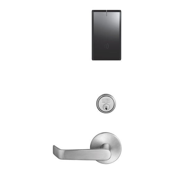
IN220 Cylindrical Lock General Description The SARGENT IN220 Cylindrical lock combines superior aesthetics with the energy efficiency and streamlined architecture of Power-over-Ethernet (PoE) access control. PoE-enabled access control allows facilities to leverage existing network infrastructure for enhanced security and easier, more cost-effective installations. -
Page 5: Parts Breakdown
IN220 Cylindrical Lock Parts Breakdown PART NO./ORDER ITEM QTY. STRING DESCRIPTION IN-220-EM01-[B*]IP-B Reader assembly - black plastic IN-220-EM01-[B*]IP-W Reader assembly - white plastic IN-220-EM01-[B*]IP-MB-xxx** Reader assembly - black plastic with metal trim IN-220-EM01-[B*]IP-MW-xxx** Reader assembly - white plastic with metal trim... - Page 6 IN220 Cylindrical Lock Parts Breakdown (Continued) PART NO./ORDER STRING ITEM QTY. DESCRIPTION Outside Lever (Reference Catalog for Available Styles) 10-0043 Lever Retainer Key (In Screw Pack 10-2052) Cylinder Assembly (Reference Catalog for Available Cylinders) Rose (Reference Catalog for Avalable Styles)
-
Page 7: Installation Wiring
IN220 Cylindrical Lock Installation Wiring Overview SARGENT IN220 PoE Typical Application Network Cable Surface Mount RJ45 Network Switch (802.3af) LMT: Lock Management Tool A. PoE frame harness assembly B. PoE data hinge from McKinney (patent pending) C. PoE door harness* from McKinney D. - Page 8 IN220 Cylindrical Lock Installation Wiring (Continued) Supplied by CI Certified Integrator (CI) supplies and terminates Supplied by End User the B-Splice connector and the PoE Switch male RJ45 connector from harness to end user provided facility cable B-Splice Patch Cable...
- Page 9 IN220 Cylindrical Lock Installation Wiring (Continued) Frame Harness Installation Components and wire harness supplied by McKinney. Suggested installation: Supplied by CI Cut end / ceiling-side PoE harness: B-Splice Crimp Connector TIA/EIA 568-B Standard Wiring Wire Pair Number White/Orange Orange RJ45-M...
- Page 10 IN220 Cylindrical Lock PoE Door Harness Order of installation may vary. Refer to appropriate sections for instructions. Hinge-side harness connectors: • 4-pin male Molex connector • 6-pin male Molex connector with ground wire Lock-side harness connectors: • Ring terminal •...
-
Page 11: Lock Installation
IN220 Cylindrical Lock Lock Installation 1 Prepare Door A. Verify Hand and Bevel of Door Stand on outside of locked door when determining door hand. Fig. 1A LHRB RHRB Left Hand Left Hand Right Hand Right Hand Hinges Left Reverse Bevel... - Page 12 IN220 Cylindrical Lock 2 Install Strike Centerline of Latch Front and Strike Install strike in the door frame (Fig. 2). (2) #8-32 x 3/4" Latch Screws Fig. 2 3 Install Latchbolt 1. Install latch with beveled bolt facing the strike.
- Page 13 IN220 Cylindrical Lock 5 Lock Adjustments A. Lock Preset: • Lock body holes: 12 and 6 o’clock (Fig. 5). The lock is shipped “preset” and does not require adjustment for 1-3/4” thick doors. Outside of Door Door thickness: 1-3/4” thick Fig.
- Page 14 IN220 Cylindrical Lock 6 Through-Bolt and Door Thickness Adjustment (If Required) A. Remove Outside Lever 1. Insert key, rotate 45° clockwise and hold. 2. Depress lever retainer with push pin tool (provided). 3. Pull lever outward. Outside of Door Fig. 6A B.
- Page 15 IN220 Cylindrical Lock C. Through-Bolt and Door Thickness Adjustment 1. (If necessary) remove outside lever, scalp and spacer bushing (Fig. 6C). Spacer Bushing Scalp Outside Lever Fig. 6C 2. Rotate mounting plate to either align with through-bolt holes in door, or adjust for proper door thickness (Fig. 6D).
- Page 16 IN220 Cylindrical Lock 7 Install Lock 1. From outside of door, feed lock body harness into the lock body hole (Fig. 7A). For metal door: Feed harness through inside of door (not shown). 2. Continue to feed harness into raceway (towards top of door), exiting raceway hole on inside of door (Fig.
- Page 17 IN220 Cylindrical Lock 8 Secure Lock To Door 1. Feed wire and connector: • For wood door, feed connectors and wires through the door Inside of and up the wire run channel (Fig. 8A). Door • For metal door (not shown), feed connectors and wires into the lockbody hole and out the controller hole.
- Page 18 IN220 Cylindrical Lock 10 Outside Reader and Inside Mounting Plate Installation 1. Orient the reader so the LED lens is at the top. 2. Feed the reader harness through the door (from outside to inside). 3. Install the reader to the outside of door by aligning the mounting posts with the door preparation holes.
- Page 19 IN220 Cylindrical Lock 10 Outside Reader Installation (Continued) 4. Next feed the cables/connectors through the inside mounting assembly (and gasket if required*). 5. Secure the mounting assembly while ensuring proper alignment of outside reader and partially tighten the (2) through-bolts on the inside of the door to secure the reader (Fig. 10B).
- Page 20 IN220 Cylindrical Lock Installation of Connectors DPS (4-pin) CAUTION - Do not touch or allow debris to enter connector contacts. Secure the following connectors to their respective terminals (Fig. 11A, B): A. Secure the 4-pin DPS connector. B. Secure the 10-pin lock body assembly connector.
- Page 21 IN220 Cylindrical Lock 12 Installation of Inside Module Component Assembly 1. Insert top tabs of controller into slots on mounting plate (Fig. 12A, B). 2. Ensure proper alignment of board-to-board connectors while pivoting bottom of controller toward door until tab on bottom snaps securely into place on mounting plate.
- Page 22 IN220 Cylindrical Lock 13 Inside Cover Installation 1. Assemble cover by hooking top edge on inside mounting plate. 2. Carefully press bottom of cover toward door without pinching any wires. 3. Secure cover utilizing security allen wrench. Inside Cover Security Allen Screw Fig.
-
Page 23: Operational Check
IN220 Cylindrical Lock Operational Check 1. Insert key into cylinder and rotate (Fig. 14A). There should be no friction against lock case, wire harness or any other obstructions. 2. Check that the key retracts the latch. 3. The key should rotate freely. - Page 24 Copyright © 2016, Sargent Manufacturing Company, an ASSA ABLOY Group company. All rights reserved. Reproduction in whole or in part without the express written permission of Sargent Manufacturing Company is prohibited. ASSA ABLOY is the global leader in door opening solutions, dedicated to satisfying end-user needs for security, safety and convenience.
Need help?
Do you have a question about the IN220 and is the answer not in the manual?
Questions and answers