Advertisement
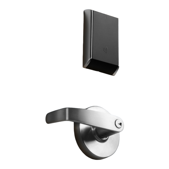
Cylindrical Lock
Installation Instructions
A8152G
04/21
Copyright 2016, 2019, 2021, Sargent Manufacturing Company, an ASSA ABLOY Group company.
All rights reserved. Reproduction in whole or in part without the express written
permission of Sargent Manufacturing Company is prohibited.
IN
Series
IN120 Wi-Fi
IN220 PoE
Cylindrical Lock
Installation Instructions
Advertisement
Table of Contents

Subscribe to Our Youtube Channel
Related Manuals for Sargent ASSA ABLOY IN Series


Summary of Contents for Sargent ASSA ABLOY IN Series
- Page 1 IN220 PoE Cylindrical Lock Installation Instructions A8152G 04/21 Copyright 2016, 2019, 2021, Sargent Manufacturing Company, an ASSA ABLOY Group company. All rights reserved. Reproduction in whole or in part without the express written permission of Sargent Manufacturing Company is prohibited.
-
Page 2: Table Of Contents
IN120 / IN220 Cylindrical Lock Table of Contents Warning ...................3 Regulatory & Power Specifications ........4 General Description ..............5 Hardware Specifications ............5 Technical Specifications ............5 Parts Breakdown ..............6 IN220 (PoE) Wiring and Installation ........8 Lock Installation ..............12 Operational Check ..............25 1-800-810-WIRE • www.sargentlock.com • A8152G... -
Page 3: Warning
Pour plus d’informations, visitez: www.P65warnings.ca.gov. Any retrofit or other field modification to a fire rated opening can potentially impact the fire rating of the opening, and SARGENT Manufacturing makes no representations or warranties concerning what such impact may be in any specific situation. When retrofitting any portion of an existing fire rated opening, or specifying and installing a new fire-rated opening, please consult with a code specialist or local code official (Authority Having Jurisdiction) to ensure compliance with all applicable codes and ratings. -
Page 4: Regulatory & Power Specifications
IN120 / IN220 Cylindrical Lock Regulatory and Power Specifications Electronic Authentication Specifications (Mobile Credentials) For Mobile Credential-Enabled versions of this electronic lock (Indicated by the credential code in the product order string): • Mobile Credentials are transmitted to the lock via Bluetooth Smart or NFC ISO/IEC14443 and must use a mobile device enabled with these technologies. -
Page 5: General Description
IN120 / IN220 Cylindrical Lock General Description The SARGENT IN120 Wi-Fi and IN220 PoE series locks offer HID multiCLASS SE technology in a ® ® streamlined design, setting a new standard for aesthetics and performance, providng heightened identity security and multiple credentials, including mobile access. -
Page 6: Parts Breakdown
IN120 / IN220 Cylindrical Lock Parts Breakdown Tools Required: • #2 Phillips screwdriver • Flat head screwdriver • Security allen wrench 3a 3b* ITEM No. DESCRIPTION Outside Escutcheon Assembly Inside Mounting Plate Assembly (includes Gasket) PoE Controller Assembly Wi-Fi Controller Assembly* (batteries included) Inside Escutcheon Assembly with Privacy Button AA alkaline batteries (6) *Consult catalog for electronic replacement part numbers... - Page 7 IN120 / IN220 Cylindrical Lock Parts Breakdown (Continued) *Adapter Plate/Spacer (10-0847) is only shipped with orders that specify 1-3/8” doors. ITEM PART No. DESCRIPTION REQ’D Outside Lever (Reference Catalog for Available Styles) 10-0043 Lever Retainer Key (In Screw Pack 10-2052) Cylinder Assembly (Reference Catalog for Available Cylinders) Rose (Reference Catalog for Avalable Styles) 10-0792...
-
Page 8: In220 (Poe) Wiring And Installation
IN120 / IN220 Cylindrical Lock Installation Wiring for IN220 Power over Ethernet (PoE) Installation Wiring Overview SARGENT IN220 PoE Typical Application Network Cable Surface Mount RJ45 Network Switch (802.3af) LMT: Lock Management Tool A. PoE frame harness assembly B. PoE data hinge from McKinney C. - Page 9 IN120 / IN220 Cylindrical Lock IN220 (PoE) Installation Wiring (Continued) Supplied by CI Supplied by End User Certified Integrator (CI) supplies and terminates the B-Splice connector and the PoE Switch male RJ45 connector from harness to end user provided facility cable B-Splice Patch Cable Crimp Connector...
- Page 10 IN120 / IN220 Cylindrical Lock IN220 (PoE) Installation Wiring (Continued) Frame Harness Installation Components and wire harness supplied by McKinney. Suggested installation: Supplied by CI Cut end / ceiling-side PoE harness: B-Splice TIA/EIA 568-B Standard Wiring Crimp Connector Wire Pair Number White/Orange Orange...
- Page 11 IN120 / IN220 Cylindrical Lock IN220 (PoE) Installation Wiring (Continued) PoE Door Harness Order of installation may vary. Refer to appropriate sections for instructions. Hinge-side harness connectors: • 4-pin male Molex connector • 6-pin male Molex connector with ground wire Lock-side harness connectors: •...
-
Page 12: Lock Installation
IN120 / IN220 Cylindrical Lock Lock Installation 1 Prepare Door A. Verify Hand and Bevel of Door Stand on outside of locked door when determining door hand. LHRB RHRB Left Hand Left Hand Right Hand Right Hand Hinges Left Reverse Bevel Hinges Right Reverse Bevel Open Inward... - Page 13 IN120 / IN220 Cylindrical Lock 2 Install Strike Centerline of Latch Front and Install strike in the door frame (Fig. 2). Strike (2) #8-32 x 3/4" Latch Screws Fig. 2 3 Install Latchbolt 1. Install latch with beveled bolt facing the strike. Inside of 2.
- Page 14 IN120 / IN220 Cylindrical Lock 5 Lock Adjustments A. Lock Preset: • Lockbody holes: 12 and 6 o’clock (Fig. 5). The lock is shipped “preset” and does not require adjustment for 1-3/4” thick doors*. Outside of Door Door thickness: 1-3/4” thick Preset Lock Fig.
- Page 15 IN120 / IN220 Cylindrical Lock 6 Through-Bolt and Door Thickness Adjustment (If Required) A. Remove Outside Lever 1. Insert key, rotate 45° clockwise and hold. 2. Depress lever retainer with push pin tool (provided). 3. Pull lever outward. Outside of Door Fig.
- Page 16 IN120 / IN220 Cylindrical Lock C. Through-Bolt and Door Thickness Adjustment 1. (If necessary) remove outside lever, scalp and spacer bushing (Fig. 6C). Spacer Bushing Scalp Outside Lever Fig. 6C 2. Rotate mounting plate to either align with through-bolt holes in door, or adjust for proper door thickness (Fig.
- Page 17 IN120 / IN220 Cylindrical Lock 7 Install Lock 1. From outside of door feed lockbody harness into the lockbody hole (Fig. 7A). For metal door: For metal door: Feed harness through inside of door (not shown). 2. Continue to feed harness into raceway (towards top of door), ex- iting raceway hole on inside of door (Fig.
- Page 18 IN120 / IN220 Cylindrical Lock 8 Secure Lock To Door 1. Feed wire and connector: • For wood door, feed connectors and wires through the door Inside of and up the wire run channel (Fig. 8A). Door • For metal door (not shown), feed connectors and wires into the lockbody hole and out the controller hole.
- Page 19 IN120 / IN220 Cylindrical Lock 10 Install IN120 / IN220 Outside Reader 1. Orient the reader (keypad) so the LED lens is at the top. 2. Feed the reader harness through the door (from outside to inside). 3. Install the reader to the outside of door by aligning the mounting posts with the door preparation holes. Hold the reader flush against door while ensuring proper alignment.
- Page 20 IN120 / IN220 Cylindrical Lock 11 Install Inside Mounting Plate Assembly 1. Next feed the cables/connectors through the inside mounting assembly and gasket. 2. Secure the mounting assembly while ensuring proper alignment of outside reader and partially tighten the (2) through-bolts on the inside of the door to secure the reader (Fig. 11A). NOTE: Cable lengths exaggerated for illustrative purposes.
- Page 21 IN120 / IN220 Cylindrical Lock 12 Preparation of Connectors Important Note: Before you secure the connectors CAUTION - Do not touch or allow debris to enter connector contacts. (grease)* Ensure connectors are covered with silicone dielectric compound SILICONE DIELECTRIC APPLY COMPOUND FILL FILL...
- Page 22 IN120 / IN220 Cylindrical Lock 13 Installation of Connectors (Continued) Important Note: If you are installing IN220 (PoE)*: E. Pull 5 1/2 inches of Ethernet cable from hole. Strip cable jacket back 3 1/2 inches. F. Separate (untwist) and straighten (8) Ethernet wires before carefully feeding through ferrite bead (Fig.
- Page 23 IN120 / IN220 Cylindrical Lock 14 Installing the Controller (Continued) 1. Insert bottom tab of controller (ensure a clear path) into slot on mounting plate (Fig. 14D, E). 2. Ensure proper alignment of board-to-board connectors (Fig. 14E) while pivoting controller toward door until two tabs on top click securely into place on mounting plate (Fig.
- Page 24 IN120 / IN220 Cylindrical Lock B. IN120 (WIFI) 1. Once controller is securely in place, place (6) “AA” alkaline batteries in the compartment, being care- ful to align polarity properly. 2. After batteries are installed, there is a slight delay; then an audible “beep”...
-
Page 25: Operational Check
IN120 / IN220 Cylindrical Lock Operational Check IMPORTANT: Be sure to test functions prior to closing door. In all cases, perform the following checks: 1. Ensure that inside lever retracts latch. • To test cylinder, the following checks apply: Insert key into cylinder and rotate: a. - Page 26 Notes...
- Page 27 IN120 / IN220 Cylindrical Lock 1-800-810-WIRE • www.sargentlock.com • A8152G...
- Page 28 New Haven, CT 06511 USA 800-727-5477 • www.sargentlock.com Founded in the early 1800s, SARGENT® is a market leader in locksets, cylinders, door closers, exit devices, electro-mechanical products and access control systems for new construction, renovation, and replacement applications. The company’s customer base includes commercial construction, institutional, and industrial markets.
Need help?
Do you have a question about the ASSA ABLOY IN Series and is the answer not in the manual?
Questions and answers