Sargent IN120 Installation Instructions Manual
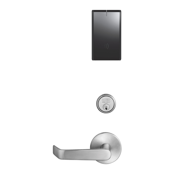
Wifi
mortise lock
Hide thumbs
Also See for IN120:
- Installation instructions manual (20 pages) ,
- Installation instructions manual (28 pages)
Advertisement
Advertisement

Related Manuals for Sargent IN120


Summary of Contents for Sargent IN120
- Page 1 IN120 WiFi Mortise Lock Installation Instructions A8151D 03/15 Copyright 2015, Sargent Manufacturing Company, an ASSA ABLOY Group company. All rights reserved. Reproduction in whole or in part without the express written permission of Sargent Manufacturing Company is prohibited.
-
Page 2: Table Of Contents
équivalente (p.i.r.e.) ne dépasse pas l’intensité nécessaire à l’établissement d’une communication satisfaisante. Any retrofit or other field modification to a fire rated opening can potentially impact the fire rating of the opening, and SARGENT Manufacturing makes no representations or warranties concerning what such impact may be in any specific situation. When retrofitting any portion of an existing fire rated opening, or specifying and installing a new fire-rated opening, please consult with a code specialist or local code official (Authority Having Jurisdiction) to ensure compliance with all applicable codes and ratings. -
Page 3: General Description
IN120 Mortise Lock General Description The IN120 WiFi lock offers the ease and flexibility of WiFi in a streamlined design, setting a new standard for aesthetics and performance. The IN120 uses IEEE 802.11 WiFi communication and a flexible feature set for easier, more cost-effective installations, allowing facilities to leverage their IT infrastructure to expand access control coverage to more doors. -
Page 4: Parts Breakdown
IN120 Mortise Lock Parts Breakdown PART NO./ORDER ITEM QTY. STRING DESCRIPTION IN-EM01-IPS-B Reader assembly - black plastic IN-EM01-IPS-W Reader assembly - white plastic IN-EM01-CP-B Reader assembly - FeliCa - black plastic IN-EM01-CP-W Reader assembly - FeliCa - white plastic Tools Required:... - Page 5 IN120 Mortise Lock Parts Breakdown (Continued) PART NO/ORDER ITEM STRING DESCRIPTION Consult Factory #41 Mortise cylinder 13-2131 97 Ring IN-120-7976-hand-fin Lock body with deadbolt with cylinder IN-120-7977-hand-fin Lock body with deadbolt without cylinder IN-120-7978-hand-fin Lock body without deadbolt with cylinder...
-
Page 6: Lock Installation
IN120 Mortise Lock Lock Installation 1 Prepare Door A. Verify Hand and Bevel of Door Stand on outside of locked door when determining door hand. LHRB RHRB Left Hand Left Hand Right Hand Right Hand Hinges Left Reverse Bevel Hinges Right... - Page 7 IN120 Mortise Lock 2 Prepare Lock Body A. Reverse Lock Hand (If Required) 1. Position lock body so that red surface of locking piece is visible. 2. Insert blade type screwdriver into locking piece slot to rotate locking piece. 3. Push locking piece toward the back of the lock body and rotate the locking piece 180°.
- Page 8 IN120 Mortise Lock 3 Install Door Position Switch (DPS) 1. Push wires through raceway toward lock prep. 2. Push DPS firmly into place by hand. Note: DO NOT TAP SWITCH WITH ANY TOOL. 3. Install magnet into door frame. Push firmly into place by hand.
- Page 9 IN120 Mortise Lock 4 Install Lock Body Note: Do not pull the lock into the pocket using the harness alone. Ensure that the wire harness is not pinched between the lock and the mortise pocket. 1. Feed the wire harness into the mortise pocket and through inside preparation hole as depicted in Figure 4.
- Page 10 Note: Do not attempt to tighten all the way. IMPORTANT: Position cylinder so that the SARGENT logo is positioned correctly. 4. Verify that orientation of cylinder has the SARGENT logo as depicted in Fig. 5A. 5. Hand tighten the cylinder clamp screw with Phillips screwdriver to prevent unscrewing of the cylinder (Fig 5C).
- Page 11 IN120 Mortise Lock 6 Assemble Outside Trim 1. With outside lever horizontal, insert the mounting posts through outside of door and lock body. Make certain the lever spindle is properly engaged inside the lock body (Fig 6A). 2. On the inside of the door, insert spindle into square hole of mortise lock (Fig 6B).
- Page 12 IN120 Mortise Lock 7 Install Inside Rose and Inside Lever Assembly 1. Place inside rose flush against door surface and rotate first counter-clockwise to seat the threads, then clockwise to securely tighten. 2. Slide lever onto spindle until fully seated. Be sure handle is horizontal and facing the hinge side of the door.
- Page 13 IN120 Mortise Lock 8 Install Thumb Turn 1. Insert thumb turn into preparation hole and engage slot in lock body. 2. Orient mounting plate so screw hole is vertical (aligned with preparation holes). 3. Secure plate with Phillips screw provided.
- Page 14 IN120 Mortise Lock 10 Outside Reader Installation 1. Orient the reader so the LED lens is at the top. 2. Feed the cable/connector through the door (from outside to inside). 3. Install the reader to the outside of door by aligning the mounting posts with the door preparation holes.
- Page 15 IN120 Mortise Lock 10 Outside Reader Installation (Continued) 4. Next feed the cables/connectors through the inside mounting assembly (and gasket if required*). NOTE: Cable lengths exaggerated for illustrative purposes. Gasket* Inside Mounting Plate Reader Harness Lock Body Harness Ground Wire Inside of Door Fig.
- Page 16 IN120 Mortise Lock 10 Outside Reader Installation (Continued) 9-24VDC Reader 5. Installation of Connectors Power* (4-pin) (24-pin) CAUTION - Do not touch or allow debris to enter connector contacts. Secure the following connectors to their respective terminals (Fig. 10C,D): A. Secure the 24-pin card reader connector.
- Page 17 IN120 Mortise Lock 11 Installing the Controller 1. Insert bottom tab of controller into slot on mounting plate (Fig. 11A, B). 2. Looking down from top of controller, ensure proper alignment of board-to-board connectors (Fig. 11B) while pivoting controller ®...
- Page 18 IN120 Mortise Lock 12 Battery Installation Before installing batteries for the first time: Remove pull tab from its position beneath the coin cell by pulling on tab in direction of arrows printed on tab (Fig. 12). 1. Place (6) “AA” alkaline batteries in the compartment, being AA Batteries (6) careful to align polarity properly.
-
Page 19: Operational Check
IN120 Mortise Lock Operational Check For 7976- and 7978-function mortise locks with cylinders: 1. Insert key into cylinder and rotate. There should be no friction against lock case, wire harness any other obstructions. 2. Check that the key retracts the latch: the key should rotate freely. - Page 20 New Haven, CT 06511 USA 800-810-WIRE (9473) • www.sargentlock.com Founded in the early 1800s, SARGENT® is a market leader in locksets, cylinders, door closers, exit devices, electro-mechanical products and access control systems for new construction, renovation, and replacement applications. The company’s customer base includes commercial construction, institutional, and industrial markets.
Need help?
Do you have a question about the IN120 and is the answer not in the manual?
Questions and answers