Emerson Rosemount 1408A Quick Start Manual
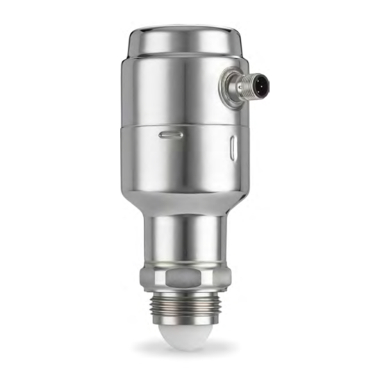
Level and flow transmitter
Hide thumbs
Also See for Rosemount 1408A:
- Reference manual (90 pages) ,
- Quick start manual (24 pages) ,
- Quick start manual (16 pages)

Related Manuals for Emerson Rosemount 1408A


Summary of Contents for Emerson Rosemount 1408A
- Page 1 Quick Start Guide 00825-0200-4480, Rev AB September 2021 ™ Rosemount 1408A Level and Flow Transmitter Non-Contacting Radar...
-
Page 2: About This Guide
1 About this guide This Quick Start Guide provides basic guidelines for the Rosemount 1408A Level and Flow Transmitter. Refer to the 1408A Reference Manual for more instructions. 1.1 Safety messages WARNING Failure to follow safe installation and servicing guidelines could result in death or serious injury. - Page 3 WARNING Physical access Unauthorized personnel may potentially cause significant damage to and/or misconfiguration of end users’ equipment. This could be intentional or unintentional and needs to be protected against. Physical security is an important part of any security program and fundamental to protecting your system.
-
Page 4: Mount Transmitter On Tank
2 Mount transmitter on tank 2.1 Mount the bracket Procedure 1. Mount the bracket on the wall/ceiling or other flat surface. 2. Apply lubricating paste on the transmitter thread. Note The paste must be approved for the application and compatible with the elastomers used. - Page 5 3. Secure the transmitter to the bracket. Mounting options: • (A) Antenna extension for open air installations • (B) Lock nut 36 mm 46 mm 2.1.1 Bracket hole pattern Figure 2-1: Hole Pattern 0.28 (7) 0.43 (11) 1.97 (50) Ø 0.28 (7) 30°...
- Page 6 2.2 Mounting onto a threaded connection Refer to Figure 2-2 for the required thread engagement length at the customer G1 process connection. Figure 2-2: Thread Engagement Length A. 0.35 to 0.63 in. (9 to 16 mm) 2.2.1 Mount on a threaded flange connection Procedure 1.
- Page 7 2. Place the flange over the gasket. 3. Tighten the bolts and nuts with sufficient torque for the flange and gasket choice. 0.75 in. (19 mm) 4. Apply lubricating paste on the transmitter thread. Note The paste must be approved for the application and compatible with the elastomers used.
- Page 8 5. Mount the transmitter on the tank. Torque 310 in-lb (35 N-m) 39 mm 2.2.2 Mount the threaded adapter version Procedure 1. Apply anti-seize paste or PTFE tape on outer threads according to your site procedures. 2. Mount the threaded adapter on the tank. 41 mm...
- Page 9 3. Apply lubricating paste on the transmitter thread. Note The paste must be approved for the application and compatible with the elastomers used. 4. Mount the transmitter on the tank. Torque 310 in-lb (35 N-m) 39 mm...
- Page 10 2.2.3 Mount on a threaded connection Procedure 1. Apply lubricating paste on the transmitter thread. Note The paste must be approved for the application and compatible with the elastomers used. 2. Mount the transmitter on the tank. Torque 310 in-lb (35 N-m) 39 mm...
-
Page 11: Prepare The Electrical Connections
3 Prepare the electrical connections 3.1 Connector type M12 (A-coded) 3.2 Power supply The transmitter operates on 18-30 Vdc at the transmitter terminals. 3.3 Outputs The transmitter provides two configurable outputs: Output 1 Digital output / IO-Link mode Output 2 Digital output or active 4-20 mA analog output 3.4 Internal power consumption <... - Page 12 Table 3-1: Pin Assignment Wire color Signal Brown 24 V White OUT2 Digital output or active 4-20 mA analog output Blue Black OUT1/IO-Link Digital output or IO-Link mode According to IEC 60947-5-2. Figure 3-2: Example Circuits 2: OUT2 2: OUT2 4: OUT1 4: OUT1 2: OUT2...
-
Page 13: Power Up Transmitter
4 Power up transmitter Prerequisites Procedure Verify the power supply is disconnected. 2. Insert the M12 connector and screw tight. See the manufacturer’s instruction manual for recommended torque. 3. Connect the power supply. - Page 14 5 Connect the transmitter to the IO-Link IO-Link devices can be set using an IO-Link USB Communicator, through the IO-Link master, or via the PLC. Procedure Start the configuration software and connect the transmitter. Figure 5-1: Connection via the IO-Link USB Communicator Figure 5-2: Connection via the IO-Link Master Figure 5-3: Connection via the PLC...
- Page 15 6 Get started with your preferred configuration tool 6.1 IO-Link configuration tools Examples: • Rosemount IO-Link Assistant (available as accessory) ® • frame applications, e.g. PACTware 6.2 Rosemount IO-Link Assistant 6.2.1 Get the latest IODD files The Rosemount IO-Link Assistant software checks and lets you download the latest IODDs for your device catalog.
- Page 16 FDT/DTM environment (e.g PACTware). Prerequisites The IODD DTM Interpreter is usually included in the FDT/DTM software installation package. It can also be downloaded from Emerson.com/Rosemount1408A. Procedure 1. Start the IODD DTM Interpreter software. 2. Select Add IODD. 3. Browse to the IODD file (.xml) and select Open.
- Page 17 7 Perform the basic setup 7.1 Set the engineering units Procedure 1. Under Menu, select Parameter → Basic Setup. 2. In the Engineering Units list, select Metric or Imperial. 3. Select Write to device. 7.2 Enter the reference height Procedure 1.
- Page 18 7.3 Configure the analog output The transmitter can be set to output the level or volume flow as a 4-20 mA signal. Procedure 1. Under Menu, select Parameter → OUT2 Analog Output. 2. In the OUT2 Configuration list, select Analog Output 4-20 mA. 3.
- Page 19 7.5 Set up the volume flow measurement Procedure 1. Under Menu, select Volume Flow. 2. In the Volume Flow Calculation Method list, select the preferred method. Choose from: • Linearization table • Parshall flume • Khafagi-Venturi flume 3. Select Volume Flow Table/Formula, and then set the parameters as desired.
-
Page 20: Product Certifications
A copy of the UKCA Declaration of Conformity can be found at the end of the Quick Start Guide. The most recent revision of the UKCA Declaration of Conformity can be found at Emerson.com/Rosemount. 8.3 Ordinary location certification As standard, the transmitter has been examined and tested to... -
Page 21: Telecommunication Compliance
6.3.1/6.3.2 and 9.4 or class 2 according to CSA 223/UL 1310. 8.4 Telecommunication compliance Rosemount 1408A, with the antenna extension fitted, is a device for measurement of level in the open air or in an enclosure. When used for measurement in an enclosure (i.e metallic or reinforced concrete... - Page 22 • Reorient or relocate the receiving antenna. • Increase the separation between the equipment and receiver. • Connect the equipment into an outlet on a circuit different from that to which the receiver is connected. • Consult the dealer or an experienced radio/TV technician for help. FCC ID K8C1408L 8.6 IC...
- Page 23 installed or operated. The Director of the DRAO may be contacted at 250-497-2300 (tel.) or 250-497-2355 (fax). (Alternatively, the Manager, Regulatory Standards, Industry Canada, may be contacted.) Le présent appareil est conforme aux CNR d'Industrie Canada applicables aux appareils radio exempts de licence. L'exploitation est autorisée aux conditions suivantes: 1.
- Page 24 8.7 Radio Equipment Directive (RED) 2014/53/EU and Radio Equipment Regulations S.I. 2017/1206 Open air installations Rosemount 1408A, when fitted with the antenna extension, complies with ETSI EN 302 729 and EN 62311. Install at a separation distance of >4 km from Radio Astronomy sites,...
- Page 25 Telecommunications Act 1997 and the relevant Standards made under The New Zealand Radio Communication Act 1989. In New Zealand, Rosemount 1408A must be installed in closed tanks (metal, reinforced concrete tanks or similar enclosure structures made of comparable attenuating material).
- Page 26 8.10 EU Declaration of Conformity Figure 8-1: EU Declaration of Conformity...
- Page 28 8.11 UKCA Declaration of Conformity Figure 8-2: UKCA Declaration of Conformity...
- Page 30 8.12 China RoHS...
- Page 32 For more information: www.emerson.com © 2021 Emerson. All rights reserved. Emerson Terms and Conditions of Sale are available upon request. The Emerson logo is a trademark and service mark of Emerson Electric Co. Rosemount is a mark of one of the Emerson family of companies.
Need help?
Do you have a question about the Rosemount 1408A and is the answer not in the manual?
Questions and answers