Emerson Rosemount 1408H Quick Start Manual
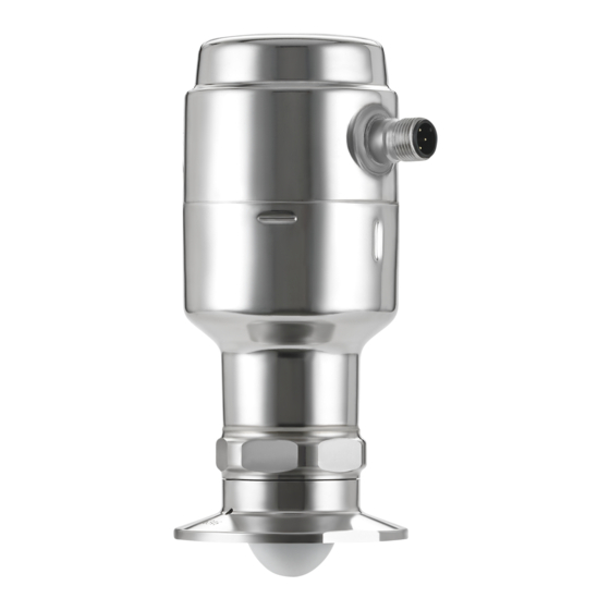
Level transmitter non-contacting radar
Hide thumbs
Also See for Rosemount 1408H:
- Reference manual (98 pages) ,
- Quick start manual (16 pages) ,
- Reference manual (90 pages)

Related Manuals for Emerson Rosemount 1408H


Summary of Contents for Emerson Rosemount 1408H
- Page 1 Quick Start Guide 00825-0100-4480, Rev AA October 2020 ™ Rosemount 1408H Level Transmitter Non-Contacting Radar...
-
Page 2: About This Guide
1 About this guide This Quick Start Guide provides basic guidelines for the Rosemount 1408H Level Transmitter. Refer to the 1408H Reference Manual more instructions. 1.1 Safety messages WARNING Failure to follow safe installation and servicing guidelines could result in death or serious injury. •... - Page 3 WARNING Physical access Unauthorized personnel may potentially cause significant damage to and/or misconfiguration of end users’ equipment. This could be intentional or unintentional and needs to be protected against. Physical security is an important part of any security program and fundamental to protecting your system.
-
Page 4: Mount Transmitter On Tank
2 Mount transmitter on tank 2.1 Mount the Tri Clamp version Procedure 1. Place a suitable gasket on top of the tank flange. 2. Lower the transmitter into the nozzle. 3. Tighten the clamp to the recommended torque (see the manufacturer’s instruction manual). - Page 5 2.2 Mount the dairy coupling (DIN 11851) Procedure 1. Place a suitable gasket on top of the tank flange. 2. Lower the transmitter into the nozzle. 3. Tighten the lock nut to the recommended torque (see the manufacturer’s instruction manual).
- Page 6 ® 2.3 Mount the VARIVENT version Procedure 1. Mount a suitable O-ring on the adapter. 2. Lower the transmitter into the nozzle. 3. Tighten the clamp to the recommended torque (see the manufacturer’s instruction manual).
- Page 7 2.4 Mount on a threaded connection Procedure 1. Grease the transmitter thread with lubricating paste. Note The paste must be approved for the application and compatible with the elastomers used. 2. Mount the transmitter on the tank. Torque 310 in-lb (35 N-m) 39 mm...
-
Page 8: Prepare The Electrical Connections
3 Prepare the electrical connections 3.1 Connector type M12 (A-coded) 3.2 Power supply The transmitter operates on 18-30 Vdc at the transmitter terminals. 3.3 Outputs The transmitter provides two configurable outputs: Output 1 Digital output / IO-Link mode Output 2 Digital output or active 4-20 mA analog output 3.4 Internal power consumption <... - Page 9 Table 3-1: Pin Assignment Wire color Signal Brown 24 V power supply White OUT2 Digital output or active 4-20 mA analog output Blue Ground line Black OUT1/IO-Link Digital output or IO-Link mode According to IEC 60947-5-2. Figure 3-2: Example Circuits 2: OUT2 2: OUT2 4: OUT1...
-
Page 10: Power Up Transmitter
4 Power up transmitter Prerequisites Procedure Verify the power supply is disconnected. 2. Insert the M12 connector and screw tight. See the manufacturer’s instruction manual for recommended torque. 3. Connect the power supply. - Page 11 5 Get started with your preferred configuration tool 5.1 IO-Link configuration tools Examples: • Rosemount IO-Link Assistant (available as accessory) ® • frame applications, e.g. PACTware 5.2 Rosemount IO-Link Assistant 5.2.1 Get the latest IODD files The Rosemount IO-Link Assistant software checks and lets you download the latest IODDs for your device catalog.
- Page 12 ® 5.3.2 Integrate IODDs into an FDT /DTM framework An IODD DTM Interpreter is required to integrate IODDs into an FDT/DTM environment (e.g PACTware). Prerequisites The IODD DTM Interpreter is usually included in the FDT/DTM software installation package. Procedure 1. Start the IODD DTM Interpreter software. 2.
- Page 13 6 Connect the transmitter to the IO-Link IO-Link devices can be set using an IO-Link USB Communicator, through the IO-Link master, or via the PLC. Procedure Start the configuration software and connect the transmitter. Figure 6-1: Connection via the IO-Link USB Communicator Figure 6-2: Connection via the IO-Link Master Figure 6-3: Connection via the PLC...
- Page 14 7 Perform the basic setup 7.1 Set the engineering units Procedure 1. Under Menu, select Parameter → Basic Setup. 2. In the Engineering Units list, select Metric or Imperial. 3. Select Write to device. 7.2 Enter the reference height Procedure 1.
- Page 15 7.3 Configure the analog output The transmitter can be set to output the level as a 4-20 mA signal. Procedure 1. Under Menu, select Parameter → Basic Setup. 2. In the OUT2 Configuration list, select Analog Output 4-20 mA. 3. In the Alarm Mode list, select Low Alarm or High Alarm. 4.
-
Page 16: Product Certifications
A copy of the EU Declaration of Conformity can be found at the end of the Quick Start Guide. The most current revision is available at Emerson.com/Rosemount. 8.2 Ordinary location certification As standard, the transmitter has been examined and tested to... - Page 17 TLPR (Tank Level Probing Radar) equipment are devices for measurement of level in a closed space only (i.e metallic or reinforced concrete or fiberglass tanks, or similar enclosure structures made of comparable attenuating material). Rosemount 1408H is TLPR device. Hardware Version Identification Number (HVIN) is 1408T. 8.4 FCC Note: This equipment has been tested and found to comply with the limits for a Class B digital device, pursuant to part 15 of the FCC Rules.
- Page 18 8.5 IC This device complies with Industry Canada’s licence-exempt RSS standard. Operation is subject to the following conditions: 1. This device may not cause harmful interference. 2. This device must accept any interference received, including interference that may cause undesired operation. 3.
- Page 19 Le présent appareil est conforme aux CNR d'Industrie Canada applicables aux appareils radio exempts de licence. L'exploitation est autorisée aux conditions suivantes: 1. l'appareil ne doit pas produire de brouillage. 2. l'appareil doit accepter tout brouillage radioélectrique subi, même si le brouillage est susceptible d'en compromettre le fonctionnement.
-
Page 20: Radio Equipment Directive (Red) 2014/53/Eu
Certificate 2827A-1408T 8.6 Radio Equipment Directive (RED) 2014/53/EU Rosemount 1408H complies with ETSI EN 302 372 (TLPR) and EN 62479. For the receiver test that covers the influence of an interferer signal to the device, the performance criterion has at least the following level of performance according to ETSI TS 103 361 [6]. - Page 21 8.7.2 Materials of construction The hygienic approvals and certificates of the transmitter rely upon the following materials used in its construction: Table 8-1: Product Contact Surfaces Item Material PTFE sealing PTFE fluoropolymer Hygienic adapter Stainless steel 300 series Hygienic adapter FKM or EPDM O-ring Table 8-2: Nonproduct Contact Surfaces...
- Page 22 8.8 EU Declaration of Conformity Figure 8-1: EU Declaration of Conformity...
- Page 24 8.9 China RoHS...
- Page 28 Emerson Terms and Conditions of Sale are available upon request. The Emerson logo is a trademark and service mark of Emerson Electric Co. Rosemount is a mark of one of the Emerson family of companies. All other marks are the property of their respective owners.
Need help?
Do you have a question about the Rosemount 1408H and is the answer not in the manual?
Questions and answers