Emerson Rosemount 1056 Quick Start Manual
Intelligent four-wire transmitter
Hide thumbs
Also See for Rosemount 1056:
- Instruction manual (127 pages) ,
- Manual (108 pages) ,
- Quick start manual (36 pages)

Related Manuals for Emerson Rosemount 1056


Summary of Contents for Emerson Rosemount 1056
- Page 1 Quick Start Guide 00825-0100-3156, Rev AC February 2022 ™ Rosemount 1056 Intelligent Four-Wire Transmitter...
- Page 2 February 2022 Safety information Your instrument purchase from Emerson is one of the finest available for your particular application. These instruments have been designed and tested to meet many national and international standards. Experience indicates that its performance is directly related to the quality of the installation and knowledge of the user in operating and maintaining the instrument.
-
Page 3: Table Of Contents
Ensure that you have received the correct model and options from your purchase order. Verify that this Quick Start Guide covers your model and options. If it does not, call the Emerson Customer Care Center at +1 800 999 9307 to request the correct Quick Start Guide. - Page 4 Quick Start Guide February 2022 Emerson.com/Rosemount...
-
Page 5: First Steps
2. If there is no apparent damage, unpack the container. Be sure all items shown on the packing list are present. If items are missing, notify Emerson immediately. Mounting Note Dimensions in the following drawings show millimeters above inches. - Page 6 Quick Start Guide February 2022 Figure 1-2: Panel mount side A. Panel mount gasket B. Four mounting brackets and screws provided with transmitter C. Panel supplied by others: maximum thickness 0.375 in (9.52 mm) Emerson.com/Rosemount...
- Page 7 February 2022 Quick Start Guide Figure 1-3: Panel mount bottom A. Six conduit openings Quick Start Guide...
- Page 8 Quick Start Guide February 2022 Figure 1-4: Panel mount cut-out A. Maximum radius Note Panel mounting seal integrity (4/4X) for outdoor applications is the end user's responsibility. Emerson.com/Rosemount...
- Page 9 February 2022 Quick Start Guide Figure 1-5: Wall mount front A. Four cover screws Quick Start Guide...
- Page 10 Quick Start Guide February 2022 Figure 1-6: Wall mount side Emerson.com/Rosemount...
- Page 11 February 2022 Quick Start Guide Figure 1-7: Pipe mount bottom A. Front panel B. Panel and pipe mount enclosure C. Conduit openings D. 2 in (51 mm) pipe mount bracket Quick Start Guide...
-
Page 12: Installation
3. Keep the transmitter and sensor wiring at least 1 ft (0.30 m) from high voltage conductors. Be sure there is easy access to the transmitter and sample conditioning system. 4. The transmitter is suitable for panel, pipe, or surface mounting. Emerson.com/Rosemount... -
Page 13: Wiring
Profibus DP communication boards will be available in the future as options for Rosemount 1056 digital communication with a host. The HART board supports Bell 202 digital communication over an analog 4-20 mA current output. Profibus DP is an open communication protocol that operates over a dedicated digital line to the host. - Page 14 USP* alarming is available only when a contacting conductivity measurement board is installed. Preparing conduit openings There are six conduit openings in all configurations of the transmitter. Note Emerson fits four of the openings with plugs upon shipment. Emerson.com/Rosemount...
- Page 15 February 2022 Quick Start Guide Figure 3-1: Conduit openings A. Front panel/keypad B. Power leads C. Alarm relay leads D. Sensor 1 cable ® ® E. 4-20 mA/HART /Profibus leads F. Sensor 2 cable G. Spare opening NOTICE Always use proper cable gland fittings and plugs for wire and cable installations.
- Page 16 Connect the conduit hub to the conduit before attaching the fitting to the transmitter. Preparing sensor cable The Rosemount 1056 is intended for use with all Rosemount sensors. Refer to the sensor Quick Start Guide for details on preparing sensor cables. Power, output, and sensor connections 3.4.1...
- Page 17 February 2022 Quick Start Guide Figure 3-2: 115/230 Vac power supply (01 ordering code) NOTICE The AC power switch is shipped in the 230 Vac position. Adjust the switch upwards to the 115 Vac position for 110 Vac to 120 Vac operation. Figure 3-3: 24 Vdc power supply (02 ordering code) This power supply automatically detects DC power and accepts 20 Vdc to 30 Vdc inputs.
- Page 18 3.4.2 Current output wiring Emerson ships all instruments with two 4-20 mA current outputs. Wiring locations for the outputs are on the main board, which is mounted on the hinged door of the transmitter. Wire the relay leads on each of the independent relays to the correct position on the main board using the lead markings (+/positive, -/negative) on the board.
- Page 19 Figure 3-5: Current output wiring 3.4.3 Alarm relay wiring Emerson supplies four alarm relays with the switching power supply (85 to 265 Vac, 03 order code) and the 24 Vdc power supply (20-30 Vdc, 02 order code). Wire the relay leads on each of the independent relays to the correct position on the power supply board using the printed lead markings (NO/ Normally open, NC/Normally closed, or Com/Common) on the board.
- Page 20 Quick Start Guide February 2022 Figure 3-6: Alarm relay wiring for Rosemount 1056 switching power supply (03 ordering code) Table 3-1: Relays NO1 (normally open 1) COM1 Relay 1 NC1 (normally closed 1) NO2 (normally open 2) COM2 Relay 2...
- Page 21 February 2022 Quick Start Guide For best electromagnetic interference (EMI) and radio frequency interference (RFI) protection, use shielded output signal cable enclosed in an earth-grounded metal conduit. AC wiring should be 14 gauge or greater. 3. Provide a switch or breaker to disconnect the transmitter from the main power supply.
- Page 22 Quick Start Guide February 2022 Figure 3-7: Contacting conductivity signal board and sensor cable leads Figure 3-8: Toroidal conductivity signal board and sensor cable leads Emerson.com/Rosemount...
- Page 23 February 2022 Quick Start Guide Figure 3-9: pH/ORP/ISE signal board and sensor cable leads Figure 3-10: Chlorine, dissolved oxygen, and ozone signal boards and sensor cable leads Quick Start Guide...
- Page 24 Quick Start Guide February 2022 Figure 3-11: Turbidity signal board with plug-in sensor connection Emerson.com/Rosemount...
- Page 25 February 2022 Quick Start Guide Figure 3-12: Flow/current input signal board and sensor cable leads Quick Start Guide...
- Page 26 Quick Start Guide February 2022 Figure 3-13: Power wiring for the Rosemount 1056 115/230 Vac power supply (01 order code) A. To main board B. Earth ground C. Neutral D. Line Emerson.com/Rosemount...
- Page 27 February 2022 Quick Start Guide Figure 3-14: Power wiring for the Rosemount 1056 85-265 Vac power supply (03 ordering code) A. To main board B. Earth ground C. Neutral D. Line Quick Start Guide...
- Page 28 Quick Start Guide February 2022 Figure 3-15: Output wiring for Rosemount 1056 main PCB A. To power supply PCB B. Analog output 1 C. Analog output 2 D. To digital input/output PCB E. To sensor 1 PCB F. To sensor 2 PCB...
- Page 29 February 2022 Quick Start Guide Figure 3-16: Power wiring for Rosemount 1056 24 Vdc power supply (02 ordering code) A. To main board Quick Start Guide...
-
Page 30: Navigating The Display
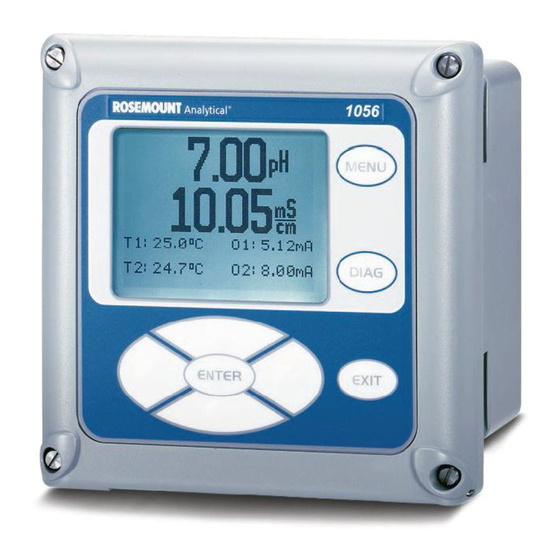
February 2022 Navigating the display User interface The Rosemount 1056 has a large display which shows two live measurement readouts in large digits and up to four additional process variables or diagnostic parameters concurrently. The display is back-lit, and you can customize the format to meet your requirements. - Page 31 4. Move the cursor to the right or left. 5. Select measurement units during operation. Main display The Rosemount 1056 displays one or two primary measurement values, up to four secondary measurement values, a fault and warning banner, alarm relay flags, and a digital communications icon.
- Page 32 • Output 2% • Measure 1 • Blank Fault and warning banner If the transmitter detects a problem with itself or the sensor, the word Fault or Warning will appear at the bottom of the display. A fault requires Emerson.com/Rosemount...
- Page 33 February 2022 Quick Start Guide immediate attention. A warning indicates a problematic condition or an impending failure. For troubleshooting assistance, press DIAG. Formatting the main display You can program the main display screen to show primary process variables, secondary process variables, and diagnostics. 1.
- Page 34 The Left key (left of ENTER) moves the cursor to the left. • The Right key (right of ENTER) moves the cursor to the right. • During all menu displays (except main display format and Quick Start), the live process measurements and secondary measurement values are Emerson.com/Rosemount...
- Page 35 February 2022 Quick Start Guide displayed in the top two lines of the upper display area. This conveniently allows display of the live values during important calibration and programming operations. Menu screens time out after two minutes and return to the main display. Quick Start Guide...
-
Page 36: Start Up The Transmitter
ENTER key. To scroll up or down or to increase or decrease the value of a digit, use the keys above and below the ENTER key. Use the Left or Right keys to move the decimal point. Emerson.com/Rosemount... - Page 37 February 2022 Quick Start Guide c. Press ENTER to store a setting. Press EXIT to leave without storing changes. Press EXIT during Quick Start to return the display to the initial startup screen (Select language). 3. Complete the steps as shown in the Figure 5-1.
- Page 38 Menu and choose Program. Follow the prompts. Figure 5-2: Rosemount 1056 menu tree 5. To return the transmitter to the factory default settings, go to Program → Reset. Call the Emerson Customer Support Center at +1-800-999-9307 if you need further support. Emerson.com/Rosemount...
-
Page 39: Approvals
February 2022 Quick Start Guide Approvals Pollution degree Installation category Altitude 6,561.7 ft (2,000 m) Humidity 80 percent to temperatures up to 88 °F (31 °C) decreasing linearly to 50 percent relative humidity at 104 °F (40 °C). Maximum 80 percent relative humidity, non-condensing. -
Page 40: Product Certifications
A copy of the EU Declaration of Conformity can be found at the end of this guide. The most recent revision of the EU Declaration of Conformity can be found at Emerson.com/Rosemount. Ordinary location certification As standard, the transmitter has been examined and tested to determine... - Page 41 February 2022 Quick Start Guide 7.4.1 USA hazardous locations Certificate FM16US0180X Standards FM Class 3600: 2011 FM Class 3611: 2004 FM Class 3810: 2005 ANSI/NEMA 250: 2003 Markings Nonincendive for use in Class I, II, and III, Division 2, Groups A, B, C, D, E, F and G; temperature class T4A Tamb = -20 °C to +50 °C;...
- Page 42 Standard 50E, 3rd edition, UL 61010-1, 3rd edition Markings Class I, Division 2, Groups A, B, C, and D; Class II, Division 2, Groups E, F, and G; Class III Maximum ambient 55 °C; temperature code T4A; enclosure Type 4X; IP66 Emerson.com/Rosemount...
-
Page 43: Eu Declaration Of Conformity
February 2022 Quick Start Guide EU Declaration of Conformity Quick Start Guide... - Page 44 Quick Start Guide February 2022 Emerson.com/Rosemount...
-
Page 45: China Rohs Table
February 2022 Quick Start Guide China RoHS Table Quick Start Guide... - Page 46 Quick Start Guide February 2022 Emerson.com/Rosemount...
- Page 47 February 2022 Quick Start Guide Quick Start Guide...
- Page 48 For more information: Emerson.com © 2022 Emerson. All rights reserved. Emerson Terms and Conditions of Sale are available upon request. The Emerson logo is a trademark and service mark of Emerson Electric Co. Rosemount is a mark of one of the Emerson family of companies.
Need help?
Do you have a question about the Rosemount 1056 and is the answer not in the manual?
Questions and answers