Table of Contents
Advertisement
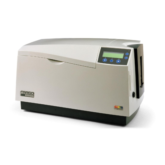
DTC500 Series Card Printer/Encoders
User Guide (Rev. 5.0)
DTC510 (Single-Sided Card Printer/Encoders)
DTC515 (Single-Sided Card Printer/Encoders)
DTC515-LC (Single-Sided Card Printer/Encoders)
DTC520 (Dual-Sided Card Printer/Encoders)
DTC525 (Dual-Sided Card Printer/Encoders)
DTC525-LC (Dual-Sided Card Printer/Encoders)
Part Number: L000699
Advertisement
Table of Contents

Related Manuals for FARGO electronics DTC510


Summary of Contents for FARGO electronics DTC510
- Page 1 DTC500 Series Card Printer/Encoders User Guide (Rev. 5.0) DTC510 (Single-Sided Card Printer/Encoders) DTC515 (Single-Sided Card Printer/Encoders) DTC515-LC (Single-Sided Card Printer/Encoders) DTC520 (Dual-Sided Card Printer/Encoders) DTC525 (Dual-Sided Card Printer/Encoders) DTC525-LC (Dual-Sided Card Printer/Encoders) Part Number: L000699...
- Page 2 DTC500 Series Card Printer/Encoders User Guide (Rev. 5.0), property of FARGO Electronics, Incorporated Copyright 2002, 2003, 2004, 2005, 2006 by FARGO Electronics, Incorporated. All rights reserved. Printed in the United States of America. Exclusive permission is granted to authorized resellers of FARGO products to reproduce and distribute this copyrighted document to authorized FARGO customers, who have signed a “no disclosure agreement”...
-
Page 3: Reviewing The Dtc500 Series Printers Overview Table
RESTRICTED USE ONLY Fargo Electronics, Inc. Reviewing the DTC500 Series Printers Overview table DTC500 Series Input Card Security Encoding Lamination Hoppers Capacity Modules Module DTC510 (Single-Sided Optional Card Printer/Encoders) DTC515 (Single-Sided Included Optional Optional Card Printer/Encoders) DTC515-LC (Single- Included Optional... -
Page 4: How To Use The Manual
RESTRICTED USE ONLY Fargo Electronics, Inc. How to use the manual The DTC500 Series Card Printer/Encoders User Guide (Rev. 5.0) is, in fact, the troubleshooting and field service manual for the entire DTC500 card printer. The manual is designed to provide Installers and Technicians with quick, efficient lookup of related procedures, components and terms. -
Page 5: Safety Messages (Review Carefully)
RESTRICTED USE ONLY Fargo Electronics, Inc. Safety Messages (review carefully) Symbol Critical Instructions for Safety purposes Danger: Failure to follow these installation guidelines can result in death or serious injury. Information that raises potential safety issues is indicated by a warning symbol (as shown to the below). -
Page 6: Dtc500 Card Printer/Encoders Overview
RESTRICTED USE ONLY Fargo Electronics, Inc. DTC500 Card Printer/Encoders Overview Reviewing the DTC500 Block Diagram Motors Sensors Parts Hopper Lift Card Detection Card Input Roller Hopper Transport Flipper Table Card Cleaning Cartridge Encoding/Flipper Feed Encoding TOF Flipper Table Roller Flipper Stepper... -
Page 7: Reviewing Dtc 525 Sequence Of Operations
RESTRICTED USE ONLY Fargo Electronics, Inc. Reviewing DTC 525 Sequence of Operations The following sequence describes a DTC525 doing a dual sided full color print job with magnetic encoding. Step Process The File information is received from the PC. The Flipper Stepper activates and rotates the Flipper Table until the Flipper Home Sensor is activated. - Page 8 RESTRICTED USE ONLY Fargo Electronics, Inc. Reviewing DTC 525 Sequence of Operations (continued) Step Process Repeat Steps 9 to 10 for each Encoding and Verification pass. The Card is centered on the Flipper Table based on input from the Flipper Table Card Sensor.
-
Page 9: Reviewing Dtc 520 Sequence Of Operations
RESTRICTED USE ONLY Fargo Electronics, Inc. Reviewing DTC 520 Sequence of Operations The following sequence describes a DTC525 doing a dual sided full color print job with magnetic encoding. Step Process The File information is received from the PC. The Flipper Stepper activates and rotates the Flipper Table until the Flipper Home Sensor detects a change in state. - Page 10 RESTRICTED USE ONLY Fargo Electronics, Inc. Reviewing DTC 520 Sequence of Operations (continued) Flipper Stepper rotates the Flipper Table a certain number of steps (based on the Flipper Offset setting) to return the Flipper Table to a level position. The Card Feed Motor feeds the Card to the Print TOF Sensor.
-
Page 11: Reviewing Dtc 515 Sequence Of Operations
RESTRICTED USE ONLY Fargo Electronics, Inc. Reviewing DTC 515 Sequence of Operations The following sequence describes a DTC515 doing a full color print job with magnetic encoding. Step Process The File information is received from the PC. The Flipper Stepper activates and rotates the Flipper Table until the Flipper Home Sensor detects a change in state. - Page 12 RESTRICTED USE ONLY Fargo Electronics, Inc. Reviewing DTC 515 Sequence of Operations (continued) Step Process Repeat Steps 9 to 10 for each Encoding and Verification pass. The Card is centered on the Flipper Table based on input from the Flipper Table Card Sensor.
-
Page 13: Reviewing Dtc 510 Sequence Of Operations
RESTRICTED USE ONLY Fargo Electronics, Inc. Reviewing DTC 510 Sequence of Operations The following sequence describes a DTC510 doing a full color print job with magnetic encoding. Step Process The File information is received from the PC. The Flipper Stepper activates and rotates the Flipper Table until the Flipper Home Sensor detects a change in state. - Page 14 RESTRICTED USE ONLY Fargo Electronics, Inc. Reviewing DTC 510 Sequence of Operations (continued) Step Process The Flipper Stepper rotates the Flipper Table a specific number of steps (based on the Flipper Offset setting) to return the Flipper Table to a level position.
-
Page 15: Reviewing Dtc500 Boot Up Sequence
RESTRICTED USE ONLY Fargo Electronics, Inc. Reviewing DTC500 Boot up Sequence Step Process The Printer checks the installed memory in the Printer. The Printers Firmware is initialized. The Headlift Motor activates and cycles the Printhead one full rotation. The Encoding Feed Motor activates and the Magnetic TOF Sensor checks for the presence of a Card. -
Page 16: Reviewing The Lamination Module Sequence Of Operations
RESTRICTED USE ONLY Fargo Electronics, Inc. Reviewing the Lamination Module Sequence of Operations The LAM sequence of operations begins after printing has occurred with the Card Printer. Step Process The card is fed onto the Lamination Module Flipper Table. The card is fed to the Card Position Sensor. - Page 17 RESTRICTED USE ONLY Fargo Electronics, Inc. Reviewing the Lamination Module Sequence of Operations (continued) Step Process The Card Feed Motor and the Lamination Ribbon Motor activate for the length of the card. The Lamination Roller Lift Motor cycles until Lamination Roller Lift Sensor detects state change.
-
Page 18: Reviewing Lamination Module Boot Up Sequence
RESTRICTED USE ONLY Fargo Electronics, Inc. Reviewing Lamination Module Boot up Sequence Step Process The Lamination Headlift turns until head up position is returned from Headlift Sensor. The Lamination Ribbon motor activates to determine the presence of a roll of lamination. -
Page 19: Table Of Contents
RESTRICTED USE ONLY Fargo Electronics, Inc. Table of Contents Reviewing the DTC500 Series Printers Overview table ________________________________________3 How to use the manual _________________________________________________________________4 Safety Messages (review carefully)________________________________________________________5 DTC500 Card Printer/Encoders Overview__________________________________________ 6 Reviewing the DTC500 Block Diagram__________________________________________________6 Reviewing DTC 525 Sequence of Operations _____________________________________________7... - Page 20 RESTRICTED USE ONLY Fargo Electronics, Inc. Troubleshooting the LCD Messages____________________________________________________65 Verifying the Encoding Settings for DTC500 Series Card Printer and Encoders__________________72 Verifying Encoder Settings for DTC 510/DTC 515 (Symptom A) ____________________________73 Verifying Encoder Settings for DTC 510/DTC 515 (Symptom B) ____________________________73...
- Page 21 RESTRICTED USE ONLY Fargo Electronics, Inc. Loading the Overlaminate _____________________________________________________________134 Adjusting the Card Lamination Module __________________________________________________137 Adjusting the Card Flattener_________________________________________________________137 Adjusting the Card Guide Rail _______________________________________________________139 Adjusting the Internal Card Guide ____________________________________________________143 Attaching the Card Lamination Module ________________________________________________145 Section 4: Printer Adjustments _________________________________________________ 151...
- Page 22 Selecting from the Menu Option Structure Tree__________________________________________253 Using the LCD Menu ________________________________________________________________254 Printing the Self-test _______________________________________________________________254 Reviewing the Gray/Align YMC (DTC510/515) and Gray/Align YMC/K (DTC520/525) Self-Test _255 Reviewing the Color/Resin YMCK Self-Test ___________________________________________255 Reviewing the Card Count YMC Self-Test _____________________________________________256 Reviewing the Standard Resin Self-Test _______________________________________________256 DTC500 Series Card Printer/Encoders User Guide (Rev.
- Page 23 Removing and installing the Card Feed Roller (D850415) _________________________________288 Installing the Sensor Holder _________________________________________________________290 Installing the new Card Input Hopper in the single Hopper units (DTC510/520) ________________293 Installing the new Card Input Hopper in the dual Hopper units (DTC515/525)__________________296 Applying the Close Door While Printing Label (L000188) _________________________________299...
- Page 24 RESTRICTED USE ONLY Fargo Electronics, Inc. Reviewing the Spare Parts List for DTC 500 Series Card Printer ____________________________318 Reviewing the Spare Parts List for the DTC500 LAM_____________________________________318 Glossary of Terms ____________________________________________________________ 319 Index _______________________________________________________________________ 339 DTC500 Series Card Printer/Encoders User Guide (Rev. 5.0)
-
Page 25: Section 1: Specifications
RESTRICTED USE ONLY Fargo Electronics, Inc. Section 1: Specifications The purpose of this section is to provide the User with specific information on the Regulatory Compliances, Agency Listings, Technical Specifications and Functional Specifications for the DTC500 Series Card Printer/Encoders User Guide (Rev. 5.0). -
Page 26: Regulatory Compliances
RESTRICTED USE ONLY Fargo Electronics, Inc. Regulatory Compliances Term Description The Printer manufacturer has been authorized by UL to represent the Card Printer as CSA Certified under CSA Standard 22.2. File Number: E145118 The Card Printer complies with the requirements in Part 15 of the FCC rules for a Class B digital device. -
Page 27: Agency Listings
2 of 5, UPC-A, EAN 13 and PDF-417 2D bar code and other symbologies (available via Windows driver). Card Input DTC510/520: Single-stack hopper, 100 cards (30 mil); auto or Hopper Capacity manual feed DTC515/525: Dual-stack hopper, 200 cards (30 mil); auto or manual feed ... - Page 28 Up to 16.7 million colors and 256 shades per pixel. Dimensions DTC510/515/520/525: 10.75 in. H x 18.5 in. W x 11 in. D (273mm x 470mm x 279mmD). DTC515-LC/525-LC: 10.75 in. H x 30.5 in. W x 11 in. D (273mm x 775mm x 279mmD).
- Page 29 Fargo Electronics, Inc. Technical Specifications (continued) Term Description Print Speed – DTC510/515: 7 seconds per card/514 cards per hour (K)* Batch Mode DTC510/515: 12 seconds per card/300 cards per hour (BO)* DTC510/515: 27 seconds per card/133 cards per hour (YMCKO)* ...
- Page 30 RESTRICTED USE ONLY Fargo Electronics, Inc. Technical Specifications (continued) Term Description Options Printer Cleaning Kit External Print Server (Windows only; required for stand-alone networking of printer/encoders) Card Lamination Module (DTC515 and DTC525 only) Embedded Fonts and Bar Codes to print from AS/400, mainframe and other systems o Code 39, Code 128 B &...
- Page 31 Printer – One year; optional Extended Warranty Program (U.S. only) Warranty Printhead – One year, unlimited pass with UltraCard Cards Weight DTC510/515/520/525: 24 lbs. (10.8 kg). DTC515-LC/DTC525-LC: 43 lbs./19.5kg LC Module: 19 lbs./8.6 kg. DTC500 Series Card Printer/Encoders User Guide (Rev. 5.0)
-
Page 32: Functional Specifications
RESTRICTED USE ONLY Fargo Electronics, Inc. Functional Specifications The card Printer utilizes two different, yet closely related printing technologies to achieve its direct-to-card print quality for Dye-Sublimation and resin thermal transfer. The card Printer will print from any IBM-PC® or compatible running Windows® 95/98/Me, Windows NT 4.0, Windows 2000 or Windows XP. - Page 33 RESTRICTED USE ONLY Fargo Electronics, Inc. Functional Specifications (continued) Function Description Resin Resin Thermal Transfer is the print method the Printer uses to print sharp Thermal black text and crisp bar codes that can be read by both infrared and visible- Transfer light bar code scanners.
-
Page 34: Printer Components: Lcd Display To Parallel Interface Port
Card Input Hopper Door to help prevent the theft of blank cards. If using the DTC510 or DTC520 Card Printers, this lock is not available. Exception Card Insert a single exception card into this slot if you would like to print onto Slot a card other than those loaded in the Card Input Hopper. - Page 35 RESTRICTED USE ONLY Fargo Electronics, Inc. Printer Components: LCD display to Serial Interface Port (continued) Component Description Printhead This Print Station component actually does the printing. (Note: This component is fragile and must not be bumped or touched with anything other than a cleaning pen.)
- Page 36 RESTRICTED USE ONLY Fargo Electronics, Inc. Printer Components: LCD display to Serial Interface Port (continued) Component Description scroll buttons These buttons are used to scroll through menus and sub-menus and to adjust certain menu options. Parallel This port connects to a Windows PC with a parallel cable.
- Page 37 RESTRICTED USE ONLY Fargo Electronics, Inc. Printer Components: LCD display to Serial Interface Port (continued) Refer to the previous table. Top Cover Printhead Print Station Card Cleaning Cartridge Securing Latches LCD Display LED Light Scroll Buttons Softkey Buttons Card Input Hopper...
-
Page 38: Printer Components: Lcd And Softkey Control Pad
RESTRICTED USE ONLY Fargo Electronics, Inc. Printer Components: LCD and Softkey Control Pad The Printer provides a four line, eighty (80) character LCD display that communicates helpful information about the Printer's operation. The top three lines of the LCD display will always be used to communicate print status, error messages and menu options. - Page 39 RESTRICTED USE ONLY Fargo Electronics, Inc. Printer Components: LCD and Softkey Control Pad (continued) Component Description Ready/Printer Once the Printer has finished its system check and with the Print and Open Screens Transfer Stations closed, the Printer will display READY to indicate that the Printer is ready for operation.
- Page 40 RESTRICTED USE ONLY Fargo Electronics, Inc. Printer Components: LCD and Softkey Control Pad (continued) Component Description The Cancel Use this button to cancel print jobs and reset the Printer for the next print button job. This Cancel function will cancel all print jobs in the Printer and will completely reset the Printer.
-
Page 41: Led Light
RESTRICTED USE ONLY Fargo Electronics, Inc. Printer Components: LCD and Softkey Control Pad (continued) Component Description LED light This light works in conjunction with the Printer's LCD display to help communicate the Printer's current status. (Note: It is especially effective when the User is too far away from the Printer to read the LCD display.) - Page 42 RESTRICTED USE ONLY Fargo Electronics, Inc. Printer Components: LCD and Softkey Control Pad (continued) Component Description Error Screens Your Printer is capable of communicating two similar yet different types of message screens: The first is called an ERROR screen. This screen appears if an error occurs and will completely stop Printer operation.
-
Page 43: Printer Components: Centronics-Type Parallel Interface
RESTRICTED USE ONLY Fargo Electronics, Inc. Printer Components: Centronics-Type Parallel Interface The card Printer is equipped with a standard 8-bit Centronics-type parallel interface port. (Note: This communication port is the means through which the Printer receives data from the computer. This section describes the pin assignments and signal specifications for this port.) -
Page 44: Printer Components: Print Ribbons
RESTRICTED USE ONLY Fargo Electronics, Inc. Printer Components: Print Ribbons The card Printer utilizes both Dye-Sublimation and/or resin thermal transfer methods to print images directly onto blank cards. Since the Dye-Sublimation and the resin thermal transfer print methods (each) provide their own unique benefits, print Ribbons are available in resin- only, Dye-Sublimation-only and combination Dye-Sublimation/resin versions. -
Page 45: Printer Components: Blank Cards
RESTRICTED USE ONLY Fargo Electronics, Inc. Printer Components: Blank Cards Caution: Never run cards with a contaminated, dull or uneven surface through the Printer. Printing cards on this surface can lead to poor print quality and can greatly reduce the life of the Printhead. Always store the card stock in its original packaging or in a clean, dust-free container. -
Page 46: Reviewing The Upgraded 81754 Pvc Cards
RESTRICTED USE ONLY Fargo Electronics, Inc. Reviewing the upgraded 81754 PVC Cards The upgraded 81754 PVC cards are designed for a sharper card image quality and for reduced debris and defects on Fargo Card Printers. Carefully read these detailed notes and instructions before applying this information to your Fargo printer or printers. - Page 47 RESTRICTED USE ONLY Fargo Electronics, Inc. Reviewing the upgraded 81754 PVC Cards (continued) Follow these two (2) instructions below: 1. Instruction for new 81754 PVC card stock: Increase the Printer Driver’s Dye-Sub Intensity to print with the new 81754 PVC card stock on Fargo Card Printers (S/N A319 and older).
-
Page 48: Printer Components: Card Input And Output Hoppers
RESTRICTED USE ONLY Fargo Electronics, Inc. Printer Components: Card Input and Output Hoppers Type Description Card Input The Card Input Hopper is where cards are initially loaded for printing, as Hopper shown below. The Printer's hopper provides a large door that opens up wide to make card loading simple and closes securely to help protect the card stock. -
Page 49: Printer Components: Lamination Roller
RESTRICTED USE ONLY Fargo Electronics, Inc. Printer Components: Lamination Roller Danger: The Printer’s Lamination Roller can reach temperatures exceeded 350 degree F (175 C). Use extreme caution when operating the Laminator. Never touch the Lamination Roller unless the Printer Power has been turned off for at least 20 to 30 minutes. -
Page 50: Reviewing The Card Lamination Module
RESTRICTED USE ONLY Fargo Electronics, Inc. Reviewing the Card Lamination Module Danger: The Printer’s Lamination Roller can reach temperatures exceeding 350° F (175° C). Use extreme caution when operating the Laminator. Never touch the Lamination Roller unless the Printer has been turned off for at least 20 to 30 minutes. -
Page 51: Determining The Ready Status Of The Card Lamination Module
RESTRICTED USE ONLY Fargo Electronics, Inc. Determining the Ready Status of the Card Lamination Module Caution (Technician Note): Review these requirements: If you are using a DTC525 Card Printer, you must have version 2.0.0-b2 or higher of the Printer’s Main Firmware to use the Card Lamination Module. -
Page 52: Reviewing The Lamination Top Cover And Station
RESTRICTED USE ONLY Fargo Electronics, Inc. Reviewing the Lamination Top Cover and Station Component Description Cross Reference Lamination Opens to allow access to the Lamination See the Loading the Top Cover Station, overlaminate and card path. Overlaminate in Section 3, page 134. -
Page 53: Reviewing The Securing Latches And Lamination Led Light
RESTRICTED USE ONLY Fargo Electronics, Inc. Reviewing the Securing Latches and Lamination LED light Component Description Cross Reference Securing Locks the Lamination Station securely in See the Using the Latches place when closed. Lamination tab (only with the Card Lamination Module) in Section 5, page 228. -
Page 54: Reviewing The Cancel Button
RESTRICTED USE ONLY Fargo Electronics, Inc. Reviewing the Cancel button Component Description Cross Reference Cancel The Cancel button serves to cancel the See the Section 3: Card Button current lamination job and reset the Card Lamination Module Lamination Module for the next lamination page 133. -
Page 55: Reviewing The Resume (Pause) Button
RESTRICTED USE ONLY Fargo Electronics, Inc. Reviewing the Resume (pause) button Component Description Cross Reference Resume Press the Resume button to resume See the Using the Lamination (pause) operation after an error condition is tab (only with the Card button cleared. -
Page 56: Reviewing The Rejection Card Hopper And Card Output Hopper
RESTRICTED USE ONLY Fargo Electronics, Inc. Reviewing the Rejection Card Hopper and Card Output Hopper Component Description Cross Reference Rejection The Rejection Card Hopper helps to See the Using the Card Hopper separate potentially bad cards from a stack Lamination tab (only with... -
Page 57: Reviewing The Module And Printer Interaction
RESTRICTED USE ONLY Fargo Electronics, Inc. Reviewing the Module and Printer interaction Term Description Cross Reference Module The Card Lamination Module works in See the Using the Lamination conjunction with the Printer to apply a tab (only with the Card... -
Page 58: Reviewing The Module And Lcd Display Interaction
RESTRICTED USE ONLY Fargo Electronics, Inc. Reviewing the Module and LCD display interaction Term Description Cross Reference Module For ease of operation, the Card See the Using the Lamination and LCD Lamination Module works in tandem with tab (only with the Card... -
Page 59: Reviewing The Module's Programmed Default Temperature
RESTRICTED USE ONLY Fargo Electronics, Inc. Reviewing the Module’s Programmed Default Temperature Term Description Reference Programmed Upon initial power up, the Lamination See the Using the Lamination Default Module is programmed to heat the tab (only with the Card Temperature... -
Page 60: Reviewing The Laminator Temperature Adjustment
RESTRICTED USE ONLY Fargo Electronics, Inc. Reviewing the Laminator Temperature Adjustment Term Description Laminator To change the temperature of the See the Using the Lamination Temperature Laminator, adjust its temperature through tab (only with the Card Adjustment the Lamination tab within the Printer Lamination Module) in Section Driver setup window. -
Page 61: Reviewing The Overlaminates
RESTRICTED USE ONLY Fargo Electronics, Inc. Reviewing the Overlaminates IMPORTANT! Fargo Card Printers require highly specialized overlaminates to function properly. To maximize Printer life, reliability, printed card quality and durability, you must use only Fargo Certified Supplies. For this reason, the Fargo warranty is void, where not prohibited by law, if you use non-Fargo Certified Supplies. -
Page 62: Reviewing The Cr-90 Or Cr-100 Patch Size
RESTRICTED USE ONLY Fargo Electronics, Inc. Reviewing the CR-90 or CR-100 Patch Size Term Description Cross Reference CR-90 or PolyGuard overlaminate is available in a See the Loading the CR-100 standard CR-80 patch size as well as a CR- Overlaminate procedure in 90 and CR-100 patch size for laminating Section 3, page 134. -
Page 63: Reviewing The Visual Security Solutions
RESTRICTED USE ONLY Fargo Electronics, Inc. Reviewing the Visual Security Solutions VeriMarkTM Cards - 2-D holographic foil application VeriMarkTM Cards are a low cost, customized 2-D holographic foil application, that is made in two steps. The first step is to emboss a base foil 1.9 cm (L) x 1.3 cm (H) onto the surface of a blank white card. -
Page 64: Visual Security Card Stock - Tolerances
RESTRICTED USE ONLY Fargo Electronics, Inc. Visual Security Card Stock - Tolerances Tolerance of base foil placement will equal +/- .010" from the nearest edges of the card Tolerance of layered foil will equal +/- .010" VeriMarkTM - Application Specifications VeriMarkTM foils will cover a dimensional area of 1.9 cm length x 1.3 cm height. -
Page 65: Section 2: General Troubleshooting
RESTRICTED USE ONLY Fargo Electronics, Inc. Section 2: General Troubleshooting IMPORTANT! Fargo Card Printers require highly specialized print Ribbons to function properly. To maximize Printer life, reliability, printed card quality and durability, you must use only Fargo Certified Supplies. For this reason, your Fargo warranty is void, where not prohibited by law, if you use non-Fargo Certified Supplies. - Page 66 RESTRICTED USE ONLY Fargo Electronics, Inc. Troubleshooting the LCD Messages (continued) Message Cause Solution Card Jam Indicates that a card is See Card Feeding Errors in Section 2, jammed in the Print Station or page 86. card flipping area of the Printer.
- Page 67 RESTRICTED USE ONLY Fargo Electronics, Inc. Troubleshooting the LCD Messages (continued) Message Cause Solution EE Checksum Indicates that the permanent See Resolving the EE Checksum Error circuit board memory is bad. Error in Section 7, page 246. EE Memory Error...
- Page 68 RESTRICTED USE ONLY Fargo Electronics, Inc. Troubleshooting the LCD Messages (continued) Message Cause Solution Head Resistance The LCD requires that a Enter a value for head resistance in Error value be input for the Print the LCD's Printer Setup menu.
- Page 69 RESTRICTED USE ONLY Fargo Electronics, Inc. Troubleshooting the LCD Messages (continued) Message Cause Solution Mag Encode Indicates that the card's See Resolving the Failed Magnetic Failed Magnetic Stripe was not Encode Error Message in Section 2, encoded properly. page 95.
- Page 70 RESTRICTED USE ONLY Fargo Electronics, Inc. Troubleshooting the LCD Messages (continued) Message Cause Solution Print Data Indicates that the print data See Communications Errors in sent to the Printer is corrupt Section 2, page 72. or has been interrupted. Print Ribbon Low...
- Page 71 RESTRICTED USE ONLY Fargo Electronics, Inc. Troubleshooting the LCD Messages (continued) Message Cause Solution Smart Encode The card's smart chip was See Resolving the Failed Smart Failed not encoded properly. Encode Error Message in Section 2, page 95. Starting Self-test...
-
Page 72: Verifying The Encoding Settings For Dtc500 Series Card Printer And Encoders
RESTRICTED USE ONLY Fargo Electronics, Inc. Verifying the Encoding Settings for DTC500 Series Card Printer and Encoders The purpose of this Technical Update is to clarify Encoding Settings in the DTC500 Series Card Printer/Encoders. To ensure the proper function of your DTC500 Series Printer, all of the Printer’s Encoding Options must be set correctly in the Printer’s LCD display. -
Page 73: Verifying Encoder Settings For Dtc 510/Dtc 515 (Symptom A)
RESTRICTED USE ONLY Fargo Electronics, Inc. Verifying Encoder Settings for DTC 510/DTC 515 (Symptom A) Symptoms of incorrect settings (Symptom A): Printer will try to rotate the Flipper Table during a print job. The Flipper (however) is not powered and the printer will stall out with a Flipper Jam or Data Time Out error.Table 1 (DTC 510 and DTC 515), Technical Update No. - Page 74 RESTRICTED USE ONLY Fargo Electronics, Inc. Verifying Encoder Settings for DTC 510/DTC 515 (Symptom B) (continued) Printer Model Part No. Proper Encoder Display Settings DTC 510 JIS II Magnetic Encoder 85305 Installed Smart None DTC 515 JIS II Magnetic Encoder...
- Page 75 RESTRICTED USE ONLY Fargo Electronics, Inc. Verifying Encoder Settings for DTC 510/DTC 515 (Symptom B) (continued) Printer Model Part No. Proper Encoder Display Settings DTC 510 Docking Station, MIFARE 91106 None Encoder, HID Prox Encoder Smart Installed 91206 DTC 515 Docking Station, MIFARE...
- Page 76 RESTRICTED USE ONLY Fargo Electronics, Inc. Verifying Encoder Settings for DTC 510/DTC 515 (Symptom B) (continued) Printer Model Part No. Proper Encoder Display Settings DTC 510 Docking Station, Magnetic 91111 Installed Encoder, Contact Smart Card Encoder, MIFARE Encoder Smart Installed...
-
Page 77: Verifying The Encoding Settings For The Dtc 520/Dtc 525
RESTRICTED USE ONLY Fargo Electronics, Inc. Verifying the Encoding Settings for the DTC 520/DTC 525 Symptoms of incorrect settings: Printers card feed motor for the flipper table will rotate backwards and then produce a Card Jam error. Printer Model Part No. - Page 78 RESTRICTED USE ONLY Fargo Electronics, Inc. Verifying the Encoding Settings for the DTC 520/DTC 525 (continued) Printer Model Part No. Proper Encoder Display Settings DTC 520 Docking Station + Magnetic 85406 Installed Encoder Smart Installed DTC 525 Docking Station + Magnetic...
- Page 79 RESTRICTED USE ONLY Fargo Electronics, Inc. Verifying the Encoding Settings for the DTC 520/DTC 525 (continued) Printer Model Part No. Proper Encoder Display Settings DTC 520 Docking Station, MIFARE 91306 None Encoder, HID Prox Encoder Smart Installed DTC 555 Docking Station, MIFARE...
- Page 80 RESTRICTED USE ONLY Fargo Electronics, Inc. Verifying the Encoding Settings for the DTC 520/DTC 525 (continued) Printer Model Part No. Proper Encoder Display Settings DTC 520 Docking Station, Magnetic 91311 Installed Encoder, Contact Smart Card Encoder, MIFARE Encoder Smart Installed...
-
Page 81: Communications Errors
RESTRICTED USE ONLY Fargo Electronics, Inc. Communications Errors Resolving the Communication Errors Symptom(s): Incorrect output, communications error on PC or Printer, stalling, no response from Printer, no job printed, “Paper out” error. Step Procedure Confirm that the system meets the minimum requirements, as shown here: ... - Page 82 RESTRICTED USE ONLY Fargo Electronics, Inc. Resolving the Communication Errors (continued) Step Procedure Determine if there is interference from an external device. a. Do not use an A/B Switch Box or other peripheral in line with the parallel cable. b. If using a Switch Box or other peripheral, remove it while testing communication between the computer and the Printer.
- Page 83 RESTRICTED USE ONLY Fargo Electronics, Inc. Resolving the Communication Errors (continued) Step Procedure Determine the nature of the problem with printing from the application. a. Print a self-test from the Printer to ensure that the Printer (itself) is functioning properly. See the Printing the Self-test in Section 8, page 254.
- Page 84 RESTRICTED USE ONLY Fargo Electronics, Inc. Resolving the Communication Errors (continued) Step Procedure Determine if the Parallel Port mode is set correctly. a. Ensure that the Parallel Port is set to the Enhanced Communication Port (ECP) mode. (Note: The port mode can be determined by checking the Device Manager tab in the System Control Panel.)
- Page 85 RESTRICTED USE ONLY Fargo Electronics, Inc. Resolving the Communication Errors (continued) Step Procedure Determine whether there is an adequate or inadequate hard drive space. Caution: A large volume of temporary files on the computer can cause communications errors. Access the temporary files by following this process: ...
-
Page 86: Card Feeding Errors
RESTRICTED USE ONLY Fargo Electronics, Inc. Card Feeding Errors Resolving the Card Feeding Errors Symptom: Two or more cards feed at the same time or the cards will not feed at all. Step Procedure Clean the Input Roller. a. Open the Printer's top covers and remove all cards and print Ribbons from the Printer. - Page 87 RESTRICTED USE ONLY Fargo Electronics, Inc. Resolving the Card Feeding Errors (continued) Step Procedure Ensure the Card Thickness Lever is set correctly, as shown below. a. Press the Card Thickness Lever Lock and then push the Card Thickness Lever up or down to the appropriate setting.
- Page 88 RESTRICTED USE ONLY Fargo Electronics, Inc. Resolving the Card Feeding Errors (continued) Step Procedure a. Check for static build up between cards. (Note: Occasionally, a static charge will build up between the surfaces of two or more cards causing them to stick together.) b.
-
Page 89: Resolving The Card Jam On The Flipper Table
RESTRICTED USE ONLY Fargo Electronics, Inc. Resolving the Card Jam on the Flipper Table Symptom: Cards are jamming on or at the Flipper Table or a Card Jam: Flip error is displayed on the LCD. Step Procedure Verify that the Card Feed Roller on the Flipper table is not running backwards. - Page 90 Procedure Ensure that the Flipper Table is level. (Note: This procedure does not apply to Printers with a Stationary Flipper Table, such as a DTC510/515 without any Encoders installed.) a. Open the Top Cover and remove any cards that are jammed inside the Printer.
-
Page 91: Resolving The Card Hopper Jam Error Message
RESTRICTED USE ONLY Fargo Electronics, Inc. Resolving the Card Hopper Jam Error Message Step Procedure Clear any obstructions. a. Open the Input Hopper Door, as shown below. b. Remove any cards from the Input Hopper. c. Ensure that there are no cards that are partially fed out of the Card Hopper. -
Page 92: Resolving The Card Hopper Empty Error Message
RESTRICTED USE ONLY Fargo Electronics, Inc. Resolving the Card Hopper Empty Error Message Symptom: The Hopper Empty error message is displayed on the LCD. Step Procedure Refill the hopper when convenient. Be sure to load cards with the mag stripe toward the rear of the Printer. -
Page 93: Encoding Errors
RESTRICTED USE ONLY Fargo Electronics, Inc. Encoding Errors Resolving the No Magnetic Encoder Error Message Symptom: The Printer is receiving encoding data, but the Printer is not configured with this Encoder type. Step Procedure Ensure the LCD Setting correct. a. Press Select on the LCD. -
Page 94: Resolving The Failed Magnetic Encode Error Message
RESTRICTED USE ONLY Fargo Electronics, Inc. Resolving the Failed Magnetic Encode Error Message Symptom: The Magnetic Stripe was not encoded properly. Step Procedure Check to ensure that the cards are loaded with the Magnetic Stripe facing down and towards the back of the Printer. -
Page 95: Resolving The No Smart Encoder Error Message
RESTRICTED USE ONLY Fargo Electronics, Inc. Resolving the No Smart Encoder Error Message Symptom: The Printer is receiving encoding data, but the Printer is not configured with this Encoder type. Step Procedure Ensure the LCD Setting correct. a. Press Select on the LCD. -
Page 96: Removing The Card Jam In The Printer's Magnetic Encoding Area
RESTRICTED USE ONLY Fargo Electronics, Inc. Removing the Card Jam in the Printer’s Magnetic Encoding Area Symptom: A card is jammed in the magnetic encoding area of the Printer. Step Procedure Clear the jammed card. a. Open the Top Cover. -
Page 97: Removing The Card Jam In The Printer's Smart Card Encoding Area
RESTRICTED USE ONLY Fargo Electronics, Inc. Removing the Card Jam in the Printer’s Smart Card Encoding Area Symptom: A card is jammed in the Smart Card encoding area of the Printer. Step Procedure Clear the jammed card. a. Open the Top Cover. -
Page 98: Resolving The Printer Not Reading Encoded Magnetic Track Data
RESTRICTED USE ONLY Fargo Electronics, Inc. Resolving the Printer not reading Encoded Magnetic Track Data Step Procedure Verify that the cards are loaded properly with the Magnetic Stripe facing down and towards the back of the Printer. Verify that the card is encoded with magnetic data by using a magnetic imager or developer solution. - Page 99 RESTRICTED USE ONLY Fargo Electronics, Inc. Resolving the Printer not reading Encoded Magnetic Track Data (continued) See the previous procedure in this section. DTC500 Series Card Printer/Encoders User Guide (Rev. 5.0)
-
Page 100: Resolving The Magnetic Stripe Data Being Printed On A Card Problem
RESTRICTED USE ONLY Fargo Electronics, Inc. Resolving the Magnetic Stripe Data being printed on a Card problem Step Procedure Confirm that the application is formatting the magnetic string correctly. See the Sending the Track Information procedure in Section 3, page 196. -
Page 101: Printing Process Errors
RESTRICTED USE ONLY Fargo Electronics, Inc. Printing Process Errors Resolving the Ribbon Alignment Error Message Step Procedure Check that the Ribbon is loaded properly and completely seated on the hubs. Check that the marks on the Ribbon are complete. a. Check the Motor operation to ensure that the Ribbon moves in both Forward and Backward directions on Power Up. -
Page 102: Resolving The Print Ribbon Error Message
RESTRICTED USE ONLY Fargo Electronics, Inc. Resolving the Print Ribbon Error Message Symptom: The Print Ribbon is not installed properly or it has run out, jammed, broken or been damaged. Step Procedure See Resolving Ribbon Alignment Errors in Section 2, page 101, for details. -
Page 103: Resolving The Wrong Print Ribbon Error Message
RESTRICTED USE ONLY Fargo Electronics, Inc. Resolving the Wrong Print Ribbon Error Message Symptom: The Print Ribbon (installed in the Printer) does not match the Ribbon type (selected in the Printer driver). Step Procedure Verify that the Ribbon is installed properly by ensuring that: ... -
Page 104: Resolving The Unknown Ribbon Type Error Message
RESTRICTED USE ONLY Fargo Electronics, Inc. Resolving the Unknown Ribbon Type Error Message Symptom: The Printer is unable to determine the type of Ribbon installed. Step Procedure Verify the Ribbon type. a. Ensure that the print Ribbon installed in the Printer is a DTC Ribbon. -
Page 105: Resolving The Headlift Error Message
RESTRICTED USE ONLY Fargo Electronics, Inc. Resolving the Headlift Error Message Symptom: The Printer was unable to raise or lower the Printhead. Step Procedure Press the Resume button to retry. If the Headlift does not rotate, check the Headlift Motor (A000124) to ensure that it is running. -
Page 106: Resolving The Printer Pausing Between Panels Error
RESTRICTED USE ONLY Fargo Electronics, Inc. Resolving the Printer pausing between panels error Symptom: The Printhead Fan is not operating properly. Step Procedure Confirm that the fan operates correctly. a. Upon power up, the fan should run momentarily and shut off. -
Page 107: Resolving The Printhead Temp Error Message
RESTRICTED USE ONLY Fargo Electronics, Inc. Resolving the Printhead Temp Error Message Symptom: The Printhead Temperature Regulator is not functioning properly. Step Procedure Reboot the Printer. If the problem persists, remove the Printhead and ensure that the Printhead Cables are seated properly. See the Replacing the Printhead Components procedure in Section 5, page Error! Bookmark not defined.. -
Page 108: Resolving The Flipper Alignment Error Message
RESTRICTED USE ONLY Fargo Electronics, Inc. Resolving the Flipper Alignment Error Message Symptom: A Flipper Alignment error was displayed on the LCD. Step Procedure Check for any obstruction. a. Open the Top Lid. b. Remove the Ribbon. c. Ensure that there are no obstructions. -
Page 109: Firmware Errors
RESTRICTED USE ONLY Fargo Electronics, Inc. Firmware Errors Resolving the Update Firmware Now The system Firmware must be updated for one of these reasons: The previous Firmware update was unsuccessful. The program data is corrupt. The Printer model does not correspond with the installed Firmware model number. - Page 110 RESTRICTED USE ONLY Fargo Electronics, Inc. Resolving an Upgrade Failed error (continued) Step Procedure Ensure that the proper procedure is being used. See the Firmware Updater Application Program procedure in Section 9, page 272. a. Follow the instructions on the attached DTC Firmware Upgrade Guide to insure that the correct data is being transferred to the Printer.
- Page 111 RESTRICTED USE ONLY Fargo Electronics, Inc. Resolving an Upgrade Failed error (continued) See the previous procedure in this section. Continued on the next page DTC500 Series Card Printer/Encoders User Guide (Rev. 5.0)
-
Page 112: Resolving A Program Exception Error
RESTRICTED USE ONLY Fargo Electronics, Inc. Resolving a Program Exception Error Symptom: An error has occurred in the Printers Firmware and a Program Exception Error. Step Procedure Restart the Printer and attempt to print the card again. a. If no Error is displayed, continue printing. -
Page 113: Diagnosing The Image Problems
RESTRICTED USE ONLY Fargo Electronics, Inc. Diagnosing the Image Problems Resolving the Pixel failure problems Symptom: A thin line or scratch travels the entire length of the card. Step Procedure Check the card stock for scratches. Replace the cards (as needed). - Page 114 RESTRICTED USE ONLY Fargo Electronics, Inc. Resolving the Pixel failure problems (continued) Step Procedure Replace the Cleaning Tape. a. Open the Printer's Top Cover. b. Pull the Cleaning Cartridge out of the Printer. c. Open the Cleaning Cartridge by pressing on the release tab of the clear Cleaning Cartridge Cover and pulling the cover up.
- Page 115 RESTRICTED USE ONLY Fargo Electronics, Inc. Resolving the Pixel failure problems (continued) Step Procedure Clean the Platen Rollers. a. Leave the Printer power ON and open the Top Cover and Printhead Arm. b. Remove the print Ribbon. c. Locate the Print Platen Roller, as shown below.
-
Page 116: Resolving The Card Surface Debris Problems
RESTRICTED USE ONLY Fargo Electronics, Inc. Resolving the Card surface debris problems Symptom: Prints have spots (white or colored voids) and/or dust on them, as shown after Step 4 in this procedure. Step Procedure Be sure the cards are clean and stored in a dust-free environment. - Page 117 RESTRICTED USE ONLY Fargo Electronics, Inc. Resolving the Card surface debris problems (continued) Step Procedure Replace the Cleaning Tape. a. Open the Printer's Top Cover. b. Pull the Cleaning Cartridge out of the Printer. c. Open the Cleaning Cartridge by pressing on the release tab of the clear Cleaning Cartridge Cover and pulling the cover up.
- Page 118 RESTRICTED USE ONLY Fargo Electronics, Inc. Resolving the Card surface debris problems (continued) Step Procedure Clean the Platen Roller. a. Leave the Printer power ON and open the Top Cover and Printhead Arm. b. Remove the print Ribbon. c. Locate the Platen Roller, as shown below.
-
Page 119: Resolving The Incorrect Image Darkness Problems
RESTRICTED USE ONLY Fargo Electronics, Inc. Resolving the incorrect Image Darkness problems Symptom: Printed cards are too dark or too light, as shown on the next page. Step Procedure Run a Self-Test from the Printer. See the Printing the Self-test in Section 8, page 254. - Page 120 RESTRICTED USE ONLY Fargo Electronics, Inc. Resolving the incorrect Image Darkness problems (continued) See previous procedure in this section. DTC500 Series Card Printer/Encoders User Guide (Rev. 5.0)
- Page 121 RESTRICTED USE ONLY Fargo Electronics, Inc. Resolving the incorrect Image Darkness problems (continued) See previous procedure in this section. Continued on the next page DTC500 Series Card Printer/Encoders User Guide (Rev. 5.0)
-
Page 122: Resolving The Ribbon Wrinkle Problems
RESTRICTED USE ONLY Fargo Electronics, Inc. Resolving the Ribbon wrinkle problems Symptom: Printed cards have off-colored lines or streaks on them, as shown on the next page. Step Procedure Confirm that the Printer is using the most current driver from: http://www.fargo.com... - Page 123 RESTRICTED USE ONLY Fargo Electronics, Inc. Resolving the Ribbon wrinkle problems (continued) Step Procedure Check the Printhead for debris and burrs. DTC500 Series Card Printer/Encoders User Guide (Rev. 5.0)
-
Page 124: Resolving The Excessive Resin Printing Problems
RESTRICTED USE ONLY Fargo Electronics, Inc. Resolving the excessive Resin Printing problems Symptom: Black resin text and barcodes appear smeared or too thick, as shown below. Step Procedure Reduce the Resin Heat setting within the Image Color tab of the Printer driver. - Page 125 RESTRICTED USE ONLY Fargo Electronics, Inc. Resolving the excessive Resin Printing problems (continued) See the previous procedure in this section. DTC500 Series Card Printer/Encoders User Guide (Rev. 5.0)
-
Page 126: Resolving The Incomplete Resin Printing Problems
RESTRICTED USE ONLY Fargo Electronics, Inc. Resolving the incomplete Resin Printing problems Symptom: Black resin text and barcodes appear faded or too light, as shown below. Step Procedure Reduce the Resin Heat setting within the Image Color tab of the Printer driver. - Page 127 RESTRICTED USE ONLY Fargo Electronics, Inc. Resolving the incomplete Resin Printing problems (continued) See the previous procedure in this section. DTC500 Series Card Printer/Encoders User Guide (Rev. 5.0)
-
Page 128: Resolving The Cut Off Or Off-Center Card Image Problems
RESTRICTED USE ONLY Fargo Electronics, Inc. Resolving the cut off or off-center Card Image problems Symptom: The printing is cut off or is not centered on the card. This causes a white border to appear on the card, as shown below. -
Page 129: Resolving The Poor Image Quality Problems
RESTRICTED USE ONLY Fargo Electronics, Inc. Resolving the poor Image Quality problems Symptom: The photos on the cards look pixilated or grainy, as shown below. Step Procedure Use a high-resolution, 24-bit color image to always capture an image: at a 24-bit color setting ... -
Page 130: Printing A Test Image
RESTRICTED USE ONLY Fargo Electronics, Inc. Printing a Test Image Step Procedure Choose Print Test Image to select a preset test image. (Note: These images help to determine if the Printer is functioning properly.) Scroll to the desired test image from the Select Test Image options and press the Select button. -
Page 131: Reviewing The Color/Resin Ymck Self-Test
RESTRICTED USE ONLY Fargo Electronics, Inc. Reviewing the Color/Resin YMCK Self-Test Step Procedure Use this card to determine Image Placement and confirm that (a) the image colors are properly reproduced and (b) the Resin Panel is printing properly. (Note: The Image consists of twelve spot colors, YMC and RGB, as well as gray density bars and thin resin lines.) -
Page 132: Reviewing The Card Count Self-Test
RESTRICTED USE ONLY Fargo Electronics, Inc. Reviewing the Card Count Self-Test Step Procedure Use this card to view counts for Card Count (CC), Pass Count (PC) and Transfer Count (TC) and Lamination Count (LC). The Card Count is the total number of cards the Printer has produced. Pass Count is the total number of print passes made by the Printhead. -
Page 133: Section 3: Card Lamination Module
RESTRICTED USE ONLY Fargo Electronics, Inc. Section 3: Card Lamination Module The purpose of this section is to provide the User with specific information on Printer adjustment procedures. Safety Messages (review carefully) Symbol Critical Instructions for Safety purposes Danger: Failure to follow these installation guidelines can result in death or serious injury. -
Page 134: Loading The Overlaminate
RESTRICTED USE ONLY Fargo Electronics, Inc. Loading the Overlaminate The loading process for both the Thermal Transfer Film and the PolyGuard overlaminate material is the same. Refer to the following steps to load either type of overlaminate into the Printer. - Page 135 RESTRICTED USE ONLY Fargo Electronics, Inc. Loading the Overlaminate (continued) Step Procedure Place the supply end of the overlaminate roll in between the two black Lamination Drive Hubs. (Note: The smaller Lamination Drive Hub closest to the front of the lamination module is spring loaded. Use the end of the supply roll with the black core plug to push this hub in when inserting the overlaminate roll.
- Page 136 RESTRICTED USE ONLY Fargo Electronics, Inc. Loading the Overlaminate (continued) Step Procedure Close the lamination module. When you start to print, the Lamination Drive Hubs will automatically engage the overlaminate core notches. Caution: Do not reverse the overlaminate roll. Damage may occur to the lamination Roller! DTC500 Series Card Printer/Encoders User Guide (Rev.
-
Page 137: Adjusting The Card Lamination Module
RESTRICTED USE ONLY Fargo Electronics, Inc. Adjusting the Card Lamination Module The Card Printer supports the attachment of an optional Card Lamination Module. This module can be ordered pre-installed on the Printer from the factory or can be ordered separately as a field upgradeable module. Once attached, the Card Lamination Module allows you to apply Fargo certified overlaminates for more secure, tamper-resistant cards. - Page 138 RESTRICTED USE ONLY Fargo Electronics, Inc. Adjusting the Card Flattener (continued) Step Procedure If laminated cards are bowing upward, turn the Card Flattener Adjustment Knob clockwise. (Note: This pushes the flattener Roller down to increase the reverse bending pressure. For best results, turn the knob one full rotation, then print and laminate a test card.
-
Page 139: Adjusting The Card Guide Rail
RESTRICTED USE ONLY Fargo Electronics, Inc. Adjusting the Card Guide Rail If applying PolyGuard overlaminate, you may find that the individual patch from the overlaminate roll may be off-center when applied to a card. (Note: Although the patch placement will vary slightly from card to card, they should never hang over the edge of the card.) See the Using the Lamination tab (only with Card Lamination Module) procedure in... - Page 140 RESTRICTED USE ONLY Fargo Electronics, Inc. Adjusting the Card Guide Rail (continued) Step Procedure Slightly loosen the two (2) screws which fasten the Card Guide Rail to the Printer's main chassis. If the PolyGuard patch is being placed more toward a card's top edge (as shown), move the Card Guide Rail slightly toward the rear of the Printer (opposite the direction you would like the patch to move).
- Page 141 RESTRICTED USE ONLY Fargo Electronics, Inc. Adjusting the Card Guide Rail (continued) Step Procedure If the PolyGuard patch is being placed more toward a card's bottom edge (as shown), move the Card Guide Rail slightly toward the front of the Printer (opposite the direction you would like the patch to move).
- Page 142 RESTRICTED USE ONLY Fargo Electronics, Inc. Adjusting the Card Guide Rail (continued) Step Procedure Once the adjustment is complete, be sure that the card is not binding between the Card Guide Rail and the Internal Card Guide. (Note: Depending upon how much you adjusted the Card Guide Rail, you may also need to adjust the Internal Card Guide.)
-
Page 143: Adjusting The Internal Card Guide
RESTRICTED USE ONLY Fargo Electronics, Inc. Adjusting the Internal Card Guide The Internal Card Guide is what holds the card in position as it feeds through the Card Lamination Module. Step Procedure Feed a blank card into the module by inserting it through the Output Hopper and reverse feeding it by pressing the lamination module's Resume button. - Page 144 RESTRICTED USE ONLY Fargo Electronics, Inc. Adjusting the Internal Card Guide (continued) Step Procedure Slightly loosen the two screws which fasten the Internal Card Guide to the Printer's main chassis. Move the Internal Card Guide so there is a slight space of about .010"/.25mm between the card edge and the Internal Card Guide as indicated below.
-
Page 145: Attaching The Card Lamination Module
RESTRICTED USE ONLY Fargo Electronics, Inc. Attaching the Card Lamination Module The Card Lamination Module can be attached to select Printer models (DTC525 only) as a field upgradeable option. This can typically be done in 20 minutes or less and with no other tools than a phillips screw driver. - Page 146 RESTRICTED USE ONLY Fargo Electronics, Inc. Attaching the Card Lamination Module (continued) Step Procedure Set the Printer on the lamination module's Baseplate at an angle as shown. (Note: This position will make it easier to connect the Power and Communication cables.) Continued on the next page DTC500 Series Card Printer/Encoders User Guide (Rev.
- Page 147 RESTRICTED USE ONLY Fargo Electronics, Inc. Attaching the Card Lamination Module (continued) Step Procedure a. Connect the lamination module's Power Cable to the Printer's Power Port. (Note: both are labeled with a red Power label.) b. Push firmly to ensure both are securely connected. (Note: The port and cable are keyed for one way installation.)
- Page 148 RESTRICTED USE ONLY Fargo Electronics, Inc. Attaching the Card Lamination Module (continued) Step Procedure Set the Printer completely into the lamination module's Baseplate. (Note: The rubber pads on the bottom of the Printer will rest securely in the holes in the lamination module's Baseplate when the Printer is seated properly.)
- Page 149 RESTRICTED USE ONLY Fargo Electronics, Inc. Attaching the Card Lamination Module (continued) Step Procedure Gently tilt the entire Printer and Lamination Module back onto its rear cover, as shown below. (Note: Be careful not to slide the unit around in this position as scratching could occur.)
- Page 150 RESTRICTED USE ONLY Fargo Electronics, Inc. Attaching the Card Lamination Module (continued) Step Procedure While being careful not to scratch the plastic cover, remove the Fargo DTC525 model number label from the front of the Printer and replace it with the included Fargo DTC525-LC model number label.
-
Page 151: Section 4: Printer Adjustments
RESTRICTED USE ONLY Fargo Electronics, Inc. Section 4: Printer Adjustments The purpose of this section is to provide the User with specific information on Printer adjustment procedures. Safety Messages (review carefully) Symbol Critical Instructions for Safety purposes Danger: Failure to follow these installation guidelines can result in death or serious injury. -
Page 152: Adjusting The Internal Card Guide
RESTRICTED USE ONLY Fargo Electronics, Inc. Safety Messages (review carefully) (continued) IMPORTANT! Fargo Card Printers require highly specialized print Ribbons to function properly. To maximize Printer life, reliability, printed card quality and durability, you must use only Fargo Certified Supplies. For this reason, your Fargo warranty is void, where not prohibited by law, if you use non-Fargo Certified Supplies. - Page 153 RESTRICTED USE ONLY Fargo Electronics, Inc. Adjusting the Internal Card Guide (continued) Step Procedure If loading CR-80, 10 mil cards, adjust this guide (as needed) to accommodate very thin, flexible card stock. Open the Printer's Top Cover and Print Station.
-
Page 154: Printer Driver Options
RESTRICTED USE ONLY Fargo Electronics, Inc. Printer Driver options These Driver options and pictures are from the DTC500 Series driver (Version 1.3.3). Using the Device options tab DTC500 Series Card Printer/Encoders User Guide (Rev. 5.0) -
Page 155: Adjusting For The Ribbon Type
RESTRICTED USE ONLY Fargo Electronics, Inc. Adjusting for the Ribbon Type Use the Ribbon Type dropdown menu to match the Ribbon type. Step Procedure Adjust to match the Ribbon Type selection with the Ribbon Type already loaded in the Printer. See the Printer Components: Print Ribbons description in Section 1, page 44. -
Page 156: Adjusting For The Color Matching
RESTRICTED USE ONLY Fargo Electronics, Inc. Adjusting for the Color matching Use the Color Matching option to meet the requirements for the print job. Step Procedure Select None (a) if interested in print speed rather than print color, (b) if color correcting the image for printing has already been done or (c) if using third party Color Matching software. -
Page 157: Adjusting For The Resin Dither
RESTRICTED USE ONLY Fargo Electronics, Inc. Adjusting for the Resin Dither Use the appropriate Dither method according to the type of image to be printed. (Note: This option only affects those objects printed with the resin black panel.) Step Procedure Select Optimized for Graphics when printing lower quality images (e.g., clipart,... -
Page 158: Using The Print Both Sides Option (Dtc520/Dtc525 Only)
RESTRICTED USE ONLY Fargo Electronics, Inc. Using the Print Both Sides option (DTC520/DTC525 only) Use this option to automatically print on both the front and backside of a card. Step Procedure Select this option in conjunction with any application program that supports a multiple-page document, duplex printing. -
Page 159: Using The Split 1 Set Of Ribbon Panels Option (Dtc520/Dtc525 Only)
RESTRICTED USE ONLY Fargo Electronics, Inc. Using the Split 1 Set of Ribbon Panels option (DTC520/DTC525 only) Use this option to provide the most economical means of printing a dual-sided card since a single set of Ribbon panels is essentially split to print both the front and backsides of a card. -
Page 160: Using The Print Back Side First Option
RESTRICTED USE ONLY Fargo Electronics, Inc. Using the Print Back Side First option Step Procedure Select this option if you need to print the first page of a two-page document on the backside of the card. The second page of the document will be printed on the front side of the card. -
Page 161: Using The Print On Back Side Only Option (Dtc520/Dtc525 Only)
RESTRICTED USE ONLY Fargo Electronics, Inc. Using the Print on Back Side Only option (DTC520/DTC525 only) Use this option to print only onto the backside of cards. Step Procedure Select this option to print only onto the backside of cards that must have their Magnetic Stripe or Smart Card chip encoded. -
Page 162: Using The Rotate Front By 180 Degrees Option
RESTRICTED USE ONLY Fargo Electronics, Inc. Using the Rotate Front by 180 Degrees option Use this option to change the position of the printed image in relation to the set location of a card's Magnetic Stripe or smart chip. Step... -
Page 163: Using The Rotate Back By 180 Degrees Option (Dtc520/Dtc525 Only)
RESTRICTED USE ONLY Fargo Electronics, Inc. Using the Rotate Back by 180 Degrees option (DTC520/DTC525 only) Use this option to change the position of the printed image in relation to the set location of a card's Magnetic Stripe or smart chip. -
Page 164: Using The Buffer Single Card Option
RESTRICTED USE ONLY Fargo Electronics, Inc. Using the Buffer Single Card option Use this option to force the Printer's memory to Buffer or to hold only one print job at a time. Step Procedure Select this option only when printing to multiple Printers sharing print jobs over a network, which ensures that all Printers evenly share all print jobs. -
Page 165: Using The Link Card To Print Job Option
RESTRICTED USE ONLY Fargo Electronics, Inc. Using the Link Card to Print Job option Use this option to link a specific card to a specific print job. This option is used when printing and encoding e-cards. Caution: In this case, it is often critical that an e-card with a pre-encoded serial number, for example, coincide with a particular printed image. -
Page 166: Using The Disable Printing Option
RESTRICTED USE ONLY Fargo Electronics, Inc. Using the Disable Printing option Use this option to disable the printing capabilities of the Printer, yet still allow the Printer to encode cards. (Note: This option is useful to encode or re-encode cards without additional time, effort or printing supplies.) -
Page 167: Using The Image Color Tab
RESTRICTED USE ONLY Fargo Electronics, Inc. Using the Image Color tab Use this tab to adjust the color properties. Step Procedure Select the Algebraic Color Matching option (see the Device options tab window, shown below) to control the Contrast and Gamma of the printed image, as well as the individual color balance of Yellow, Magenta and Cyan (see the Image Color tab window, shown below). - Page 168 RESTRICTED USE ONLY Fargo Electronics, Inc. Using the Image Color tab (continued) Step Procedure Select the None or Monitor option (see the Device options tab, shown below) to only display the Dye-Sub Intensity and Resin Heat sliders. Control the overall darkness and lightness of the dye-sub printed image by adjusting the Dye-Sub Intensity slide by clicking and dragging the slide's box.
- Page 169 RESTRICTED USE ONLY Fargo Electronics, Inc. Using the Image Color tab (continued) Step Procedure Control the amount of heat the Printer uses (a) when printing with the resin black panel of a full-color Ribbon or (b) when printing with a resin-only Ribbon by adjusting the Resin Heat slide.
- Page 170 RESTRICTED USE ONLY Fargo Electronics, Inc. Using the Image Color tab (continued) Step Procedure Return all options to their factory settings by clicking on the Default button. DTC500 Series Card Printer/Encoders User Guide (Rev. 5.0)
-
Page 171: Using The K Panel Resin Tab
RESTRICTED USE ONLY Fargo Electronics, Inc. Using the K Panel Resin tab Use this tab to adjust the Print All Black with K Panel (options) and the Defined Areas. Use this tab to control where the resin black (K) panel of a full-color Ribbon is printed. -
Page 172: Selecting The Full Card With The K Panel Resin Tab
RESTRICTED USE ONLY Fargo Electronics, Inc. Selecting the Full Card with the K Panel Resin tab Step Procedure Select the Full Card option to print the resin black (K) panel for all black found within all areas of the image, as shown below. -
Page 173: Selecting The Defined Area(S) With The K Panel Resin Tab
RESTRICTED USE ONLY Fargo Electronics, Inc. Selecting the Defined Area(s) with the K Panel Resin tab Step Procedure Select the Defined Area(s) option to print the resin black (K) panel for all black found only in an area or areas defined, as shown below. -
Page 174: Selecting The Undefined Area(S) With The K Panel Resin Tab
RESTRICTED USE ONLY Fargo Electronics, Inc. Selecting the Undefined Area(s) with the K Panel Resin tab Step Procedure Select the Undefined Area(s) option to print the resin black (K) panel for all black found only in the space outside the areas defined, as shown below. (Note: In the card grid, black indicates the area in which the resin black (K) panel will be printed.) -
Page 175: Defining The Area To Activate The Card Grid
RESTRICTED USE ONLY Fargo Electronics, Inc. Defining the Area to activate the Card Grid Step Procedure Select on the appropriate Defined Area (see below) to activate the card grid in the upper half of the window. (Note: It is through this card grid that up to five areas can be defined, as shown below.) -
Page 176: Measuring The Total Card Area
RESTRICTED USE ONLY Fargo Electronics, Inc. Measuring the Total Card area Step Procedure Determine the area of the card to define. (Note: This area is indicated by the dashed outline, as shown below. The easiest way to determine the size of this area is to actually print a card and look at it in the same orientation as when it exits the Printer.) - Page 177 RESTRICTED USE ONLY Fargo Electronics, Inc. Measuring the Total Card area (continued) See the previous procedure in this section. DTC500 Series Card Printer/Encoders User Guide (Rev. 5.0)
-
Page 178: Defining The Positioning Of The Area On The Card
RESTRICTED USE ONLY Fargo Electronics, Inc. Defining the positioning of the area on the Card Step Procedure Once the area is sized properly, measure the location where this area is to be positioned on the card. a. Measure from the lower left corner of the card up and over to the lower left corner of where the defined area is to begin. - Page 179 RESTRICTED USE ONLY Fargo Electronics, Inc. Defining the positioning of the area on the Card (continued) See the previous procedure in this section. DTC500 Series Card Printer/Encoders User Guide (Rev. 5.0)
-
Page 180: Selecting The Print Ymc Under The K And Print K Only Options
RESTRICTED USE ONLY Fargo Electronics, Inc. Selecting the Print YMC under the K and Print K Only options Step Procedure Select the Print YMC Under K option to print all black in the designated areas with the Yellow (Y), Magenta (M) and Cyan (C) Ribbon panels directly beneath the resin black (K) panel. - Page 181 RESTRICTED USE ONLY Fargo Electronics, Inc. Selecting the Print YMC under the K and Print K Only options (continued) See the previous procedure in this section. DTC500 Series Card Printer/Encoders User Guide (Rev. 5.0)
-
Page 182: Using The Magnetic Encoding Tab
RESTRICTED USE ONLY Fargo Electronics, Inc. Using the Magnetic Encoding tab Use these options only if the Printer has an optional Magnetic Stripe Encoding Module installed. Step Procedure Select the Magnetic Encoding tab to display options for controlling the Magnetic Stripe encoding process. (Note: The following describes these options and the Printer's magnetic encoding process.) -
Page 183: Using The Encoding Mode Option
RESTRICTED USE ONLY Fargo Electronics, Inc. Using the Encoding Mode option Use the Encoding Mode option to specify which magnetic encoding standard to use. The DTC500 Series Card Printer can be installed with one of two types of factory- installed Magnetic Stripe Encoding Modules. - Page 184 RESTRICTED USE ONLY Fargo Electronics, Inc. Using the Encoding Mode option (continued) See the previous procedure in this section. DTC500 Series Card Printer/Encoders User Guide (Rev. 5.0)
-
Page 185: Encoding The Mode/Coercivity/Magnetic Track Selection
RESTRICTED USE ONLY Fargo Electronics, Inc. Encoding the Mode/Coercivity/Magnetic Track Selection Use the ISO option for encoding capability for either high- or low-Coercivity cards on tracks 1, 2 and 3. Step Procedure Select the Coercivity option to select the Magnetic Stripe type that matches the card type. - Page 186 RESTRICTED USE ONLY Fargo Electronics, Inc. Encoding the Mode/Coercivity/Magnetic Track Selection See the previous procedure in this section. DTC500 Series Card Printer/Encoders User Guide (Rev. 5.0)
-
Page 187: Using The Magnetic Track Selection Option
RESTRICTED USE ONLY Fargo Electronics, Inc. Using the Magnetic Track Selection option Use these options to customize the ISO encoded data format for each of the Magnetic Stripe's three tracks. Step Procedure Specify which of the three (3) tracks to customize by selecting one of the three track options. -
Page 188: Reviewing The Enable Mle Support Checkbox
RESTRICTED USE ONLY Fargo Electronics, Inc. Reviewing the Enable MLE Support checkbox Multi-Language Extension (MLE) support in Windows XP can cause text strings to be broken up into fragments. This fragmentation of the text string prevents magnetic encoding. Step Procedure Check this box to allow the Driver to process the fragmented text. -
Page 189: Using The Magnetic Track Options
RESTRICTED USE ONLY Fargo Electronics, Inc. Using the Magnetic Track options Use the Magnetic Track options for these purposes: Customize the ISO encoded data format for each of the Magnetic Stripe's three tracks. Customize each track independently of the other two. -
Page 190: Using The Bit Density Radio Buttons
RESTRICTED USE ONLY Fargo Electronics, Inc. Using the Bit Density radio buttons Use this option to customize the Bit Recording Density (Bits per Inch) used to encode the magnetic data on the currently selected track. The default ISO Standard selections for this... -
Page 191: Using The Ascii Offset
RESTRICTED USE ONLY Fargo Electronics, Inc. Using the ASCII Offset Use this option to customize the Character ASCII Offset used to encode the magnetic data on the currently selected track. (Note: This character-offset value is subtracted from the ASCII value of each Magnetic Stripe data character prior to encoding on the track.) -
Page 192: Using The Lrc Generation Radio Buttons
RESTRICTED USE ONLY Fargo Electronics, Inc. Using the LRC Generation radio buttons Use this option to customize the LRC Generation Mode (used to encode the magnetic data on the currently selected track). Step Procedure Select NO LRC to change the LRC Generation to none. -
Page 193: Using The Verification Option
RESTRICTED USE ONLY Fargo Electronics, Inc. Using the Verification option Use the Verification option, which instructs the Printer to verify that all magnetic data has been correctly encoded on each card. (Note: with either of these options, the number of verification retries can be specified. -
Page 194: Reviewing The Shift Data Left
RESTRICTED USE ONLY Fargo Electronics, Inc. Reviewing the Shift Data Left Use the Shift Data Left option, which applies to all tracks when selected. Step Procedure Select this option to shift the recorded magnetic data to the left-hand side of the card's Magnetic Stripe. -
Page 195: Reviewing The Iso Track Locations
RESTRICTED USE ONLY Fargo Electronics, Inc. Reviewing the ISO Track Locations The magnetic Encoding Module encodes onto tracks in accordance with an ISO 7811-2 Magnetic Stripe. For track locations, review the display below. 0.223" 0.353" 0.493" TRACK1 0.110" 0.130" TRACK2 0.110"... -
Page 196: Sending The Track Information
RESTRICTED USE ONLY Fargo Electronics, Inc. Sending the Track Information Magnetic track data is sent in the form of text strings from the application software to the Printer driver. Specific characters must be added to the magnetic data (to be encoded) in order for the Printer driver to differentiate between Magnetic Track data and the rest of the printable objects. -
Page 197: Reviewing The Ascii Code And Character Table
RESTRICTED USE ONLY Fargo Electronics, Inc. Reviewing the ASCII Code and Character Table ASCII Code Character ASCII Code Character ASCII Code Character space " < & > DTC500 Series Card Printer/Encoders User Guide (Rev. 5.0) -
Page 198: Using The Overlay/Print Area Tab
RESTRICTED USE ONLY Fargo Electronics, Inc. Using the Overlay/Print Area tab Use this option to control how the Overlay (O) Panel and/or the print area will appear on a card. (Note: This option is helpful if, to omit the overlay or printing around a card's smart chip or Magnetic Stripe. -
Page 199: Using The Overlay/Print Area Dropdown Menu
RESTRICTED USE ONLY Fargo Electronics, Inc. Using the Overlay/Print Area dropdown menu Step Procedure Select the Full Card option for the Printer to overlay and/or print the entire card. Select the Defined Area(s) option for the Printer to overlay and/or print only in the selected and defined area or areas. -
Page 200: Using The Overlay/Print Area
RESTRICTED USE ONLY Fargo Electronics, Inc. Using the Overlay/Print Area Use these Overlay/Print Area options to control both the print and overlay together or control each individually. Step Procedure Select For Print and Overlay for the defined area to apply to both the printing and overlay process. - Page 201 RESTRICTED USE ONLY Fargo Electronics, Inc. Using the Overlay/Print Area (continued) Step Procedure Select the Defined Area(s) option to activate the card grid in the upper half of the window. (Note: This allows defined areas to be created. It is through this card grid that up to five areas can be defined.)
- Page 202 RESTRICTED USE ONLY Fargo Electronics, Inc. Using the Overlay/Print Area (continued) Step Procedure When the card grid is first activated, a small black square will appear at its default size of .2" x .2"/5mm x 5mm and at its default location in the lower left- hand corner (0,0).
- Page 203 RESTRICTED USE ONLY Fargo Electronics, Inc. Using the Overlay/Print Area (continued) See the previous procedure in this section. DTC500 Series Card Printer/Encoders User Guide (Rev. 5.0)
- Page 204 RESTRICTED USE ONLY Fargo Electronics, Inc. Using the Overlay/Print Area (continued) Step Procedure Follow this procedure once the area is sized properly. a. Measure the location this desired area to be positioned on the card. b. Measure from the lower left corner of the card (up and over) to the lower left corner (for the defined area to begin).
- Page 205 RESTRICTED USE ONLY Fargo Electronics, Inc. Using the Overlay/Print Area (continued) Step Procedure a. Print the card design. b. Observe how the image is oriented on the card as it ejects from the Printer. (Note: The location of a defined area is based on the card orientation as it exits the Printer.)
-
Page 206: Using Security Options (Visual Security Solutions)
RESTRICTED USE ONLY Fargo Electronics, Inc. Using Security Options (Visual Security Solutions) The Visual Security Solutions dropdown menu list will be used to enable and select which type of visual security will be used. The Visual Security dropdown list will be selectable only on the Front side (see below). -
Page 207: Selecting Orientation - Landscape Under Card Tab
RESTRICTED USE ONLY Fargo Electronics, Inc. Selecting Orientation - Landscape under Card tab Step Procedure Select the Landscape radio button (below) under Orientation under the Card Size tab to use the Visual Security Solutions (A to D), as shown in this window. -
Page 208: Selecting The Visual Security Solutions Dropdown Menu (A To D)
RESTRICTED USE ONLY Fargo Electronics, Inc. Selecting the Visual Security Solutions dropdown menu (A to D) Step Procedure Click on the Visual Security Solutions dropdown menu (below) under the Landscape - Orientation (see above) to use the options shown in this display. -
Page 209: Selecting Orientation - Portfolio Under Card Tab
RESTRICTED USE ONLY Fargo Electronics, Inc. Selecting Orientation - Portfolio under Card tab Step Procedure Select the Portrait radio button (below) under Orientation under the Card Size tab to use the Visual Security Solutions (E to H), as shown in this window. -
Page 210: Selecting The Visual Security Solutions Dropdown Menu (E To H)
RESTRICTED USE ONLY Fargo Electronics, Inc. Selecting the Visual Security Solutions dropdown menu (E to H) Step Procedure Click on the Visual Security Solutions dropdown menu under the Portrait - Orientation (see above) to use the options shown below. DTC500 Series Card Printer/Encoders User Guide (Rev. 5.0) -
Page 211: Selecting The Verimark Radio Button
RESTRICTED USE ONLY Fargo Electronics, Inc. Selecting the VeriMark radio button Step Procedure Click on either the VeriMark or HoloMark radio button, as shown below. The foil options are used to control the size of the exclusion area. (Note: When VeriMark is selected a rectangle-sized area is excluded, HoloMark uses a square sized area.) -
Page 212: Selecting The Holomark Radio Button
RESTRICTED USE ONLY Fargo Electronics, Inc. Selecting the HoloMark radio button Step Procedure Click on the HoloMark radio button (below) for the squared-area size. DTC500 Series Card Printer/Encoders User Guide (Rev. 5.0) -
Page 213: Reviewing The Custom Verimark Card
RESTRICTED USE ONLY Fargo Electronics, Inc. Reviewing the Custom VeriMark Card The custom VeriMark image is stamped on blank, standard-sized cards. You can select one of eight positions (A to H), as shown in the Portrait and Landscape samples below. -
Page 214: Reviewing The Custom Holomark Card
RESTRICTED USE ONLY Fargo Electronics, Inc. Reviewing the Custom HoloMark Card The custom HoloMark image is stamped on blank, standard-sized cards. You can select one of eight positions (A to H), as shown in the Portrait and Landscape samples below. -
Page 215: Using Smartshield Area Dropdown Menu
RESTRICTED USE ONLY Fargo Electronics, Inc. Using SmartShield Area dropdown menu Use the SmartShield Area options, which apply only if using the Printer's optional SmartGuard Security Feature and the SmartShield option is enabled. Step Procedure Select the Apply SmartShield option to print the custom SmartShield Security Image (a) if using the Printer's optional SmartGuard Security Feature and (b) if the SmartShield option is enabled. -
Page 216: Using The Card Tab
RESTRICTED USE ONLY Fargo Electronics, Inc. Using the Card tab Use this option to control specific Printer functions. DTC500 Series Card Printer/Encoders User Guide (Rev. 5.0) -
Page 217: Selecting The Card Size
RESTRICTED USE ONLY Fargo Electronics, Inc. Selecting the Card Size Select either the CR-80 or CR-79 for the appropriate card size option from the two (2) standard card sizes. When designing a card format, always set the card size or page size within the card design program to the exact Print Length and Width dimensions listed in the Printer driver. - Page 218 RESTRICTED USE ONLY Fargo Electronics, Inc. Selecting the Card Size (continued) See the previous procedure in this section. DTC500 Series Card Printer/Encoders User Guide (Rev. 5.0)
-
Page 219: Using The Card Hopper Selection (Dtc515/Dtc525 Only) Option
RESTRICTED USE ONLY Fargo Electronics, Inc. Using the Card Hopper Selection (DTC515/DTC525 only) option This option only applies if using the DTC515 or DTC525 Card Printer models that provide a dual-stack, 200-card capacity Card Input Hopper. (Note: The Printer driver always overrides the LCD-based hopper selection. - Page 220 RESTRICTED USE ONLY Fargo Electronics, Inc. Using the Card Hopper Selection (DTC515/DTC525 only) option (cont.) See the previous procedure in this section. DTC500 Series Card Printer/Encoders User Guide (Rev. 5.0)
- Page 221 RESTRICTED USE ONLY Fargo Electronics, Inc. Using the Card Hopper Selection (DTC515/DTC525 only) option (continued) See the previous procedure in this section. DTC500 Series Card Printer/Encoders User Guide (Rev. 5.0)
-
Page 222: Reviewing The Orientation
RESTRICTED USE ONLY Fargo Electronics, Inc. Reviewing the Orientation Select either the Portrait or Landscape radio buttons for Orientation. (Note: An icon illustrating a printed card helps represent the difference between the two.) Step Procedure Select Portrait to cause the card to print in a vertical orientation. -
Page 223: Using The Test Print Button
Use this button to send a Self-Test print to the Printer. Ribbon Requirement: A Full-Color YMCKO print Ribbon is required for a DTC510/DTC515 or YMCKOK print Ribbon is required for a DTC520/DTC525. Test Print Procedure: This test print procedure can be helpful in ensuring (a) that the computer is effectively communicating with the Printer and (b) that the Printer is functioning properly. -
Page 224: Clicking On The About Button
RESTRICTED USE ONLY Fargo Electronics, Inc. Clicking on the About button Click this About button to open a dialog containing the copyright and version information about this Printer driver software. DTC500 Series Card Printer/Encoders User Guide (Rev. 5.0) -
Page 225: Using The Image Position Button
RESTRICTED USE ONLY Fargo Electronics, Inc. Using the Image Position button Use the Image Position controls to adjust the position of the overall print area to be precisely centered on a card. Step Procedure Adjust the Image Position values by clicking on the Vertical and Horizontal adjustment arrows, as shown below. - Page 226 RESTRICTED USE ONLY Fargo Electronics, Inc. Using the Image Position button (continued) When adjusting these values, keep in mind that cards always remain in the same position as they travel through the Printer, regardless of image orientation. To illustrate this, the card illustration shown in the Image Position box will flip and rotate according to whether you have selected the Portrait or Landscape radio buttons.
- Page 227 RESTRICTED USE ONLY Fargo Electronics, Inc. Using the Image Position button (continued) The following diagram represents how the printed image will move in relation to the fixed card position as positive and negative image placement values are entered. Use the Vertical adjustment to move the image more toward the rear of the Printer (if a positive number is entered) and more toward the front of the Printer (if a negative number is entered).
-
Page 228: Using The Lamination Tab (Only With Card Lamination Module)
RESTRICTED USE ONLY Fargo Electronics, Inc. Using the Lamination tab (only with Card Lamination Module) Use this option to control specific Printer functions. The Lamination Tab appears only if the Printer is equipped with the Card Lamination Module. These options allow you to control the Printer's lamination process. -
Page 229: Selecting The Lamination Position
RESTRICTED USE ONLY Fargo Electronics, Inc. Selecting the Lamination Position Step Procedure The Lamination Position control allows you to adjust the horizontal position of the PolyGuard overlaminate. This control functions in the exact same fashion as the Image Position controls, except only the horizontal position of the overlaminate requires adjustment. -
Page 230: Selecting The Lamination Side
RESTRICTED USE ONLY Fargo Electronics, Inc. Selecting the Lamination Side Step Procedure a. Select the No Lamination option if you do not want to use the Printer's built-in laminator. b. Select Laminate Front Side, Laminate Back Side or Laminate Both Sides to specify the side(s) of the card to laminate. -
Page 231: Selecting The Lamination Type
RESTRICTED USE ONLY Fargo Electronics, Inc. Selecting the Lamination Type Select one of the Lamination Type options, according to which type of lamination media is currently installed. Two types of overlaminates are supported by the driver: Film Lamination and PolyGuard lamination. Custom versions of each type are also available. -
Page 232: Selecting The Lamination Type
RESTRICTED USE ONLY Fargo Electronics, Inc. Selecting the Lamination Type Step Procedure Select the Overlay then Film Lamination option when using a Ribbon which provides a clear overlay panel. The Ribbon types which do not provide an overlay panel or support overlay printing are the resin-only Ribbons and the Full-Color YMC, YMCK and YMCKK Ribbons. -
Page 233: Adjusting The Transfer Dwell Time And Transfer Temperature
RESTRICTED USE ONLY Fargo Electronics, Inc. Adjusting the Transfer Dwell Time and Transfer Temperature Step Procedure Adjust the Transfer Dwell Time and the Transfer Temperature to control the Lamination Dwell Time or through-put speed of a card in seconds/inch and the Lamination Temperature. -
Page 234: Calibrating The Card Lamination Module's Lamination Sensor
RESTRICTED USE ONLY Fargo Electronics, Inc. Calibrating the Card Lamination Module’s Lamination Sensor Step Procedure Select the Lamination Tab's Sensors button to display options for calibrating the Card Lamination Module’s Lamination Sensor. The Lamination Sensor is what detects the start of each PolyGuard patch throughout the roll. This Sensor may occasionally need to be recalibrated. -
Page 235: Section 5: Cleaning
RESTRICTED USE ONLY Fargo Electronics, Inc. Section 5: Cleaning This Section deals with the Printer’s internal and external maintenance in regards to the unit's cleaning and general upkeep. (Note: The Printer should be cleaned on a regular basis to insure that the Printer consistently produces high quality output.) Danger: Be sure to disconnect the Printer's power cord whenever performing any type of maintenance procedure unless otherwise directed. -
Page 236: Cleaning The Printhead (850102)
RESTRICTED USE ONLY Fargo Electronics, Inc. Cleaning the Printhead (850102) Caution: Perform this procedure during every Ribbon change or after every 1,000 prints to maintain consistent print quality. Perform this procedure for streaks on the card where the color was not transferred correctly. -
Page 237: Replacing The Card Cleaning Tape
RESTRICTED USE ONLY Fargo Electronics, Inc. Replacing the Card Cleaning Tape Caution: Replace the Card Cleaning Tape approximately every 2,000 to 3,000 prints, depending on the cleanliness of the card stock or the environment in which the Printer is located. - Page 238 RESTRICTED USE ONLY Fargo Electronics, Inc. Replacing the Card Cleaning Tape (continued) See the previous procedure in this section. DTC500 Series Card Printer/Encoders User Guide (Rev. 5.0)
-
Page 239: Cleaning The Platen And Card Feed Rollers
RESTRICTED USE ONLY Fargo Electronics, Inc. Cleaning the Platen and Card Feed Rollers Caution: Clean the black, rubber Platen Roller and all of the gray (or black), rubber Card Feed Rollers within the Printer approximately every 2,000-3,000 prints, depending on the cleanliness of the card stock or the environment in which the Printer is located. - Page 240 RESTRICTED USE ONLY Fargo Electronics, Inc. Cleaning the Platen and Card Feed Rollers (continued) See the previous procedure in this section. Platen Roller Card Feed Rollers DTC500 Series Card Printer/Encoders User Guide (Rev. 5.0)
-
Page 241: Platen Roller
RESTRICTED USE ONLY Fargo Electronics, Inc. Cleaning the Platen and Card Feed Rollers (continued) See the previous procedure in this section. Card Feed Rollers Platen Roller DTC500 Series Card Printer/Encoders User Guide (Rev. 5.0) -
Page 242: Cleaning The Platen
RESTRICTED USE ONLY Fargo Electronics, Inc. Cleaning the Platen The Printer's Platen Roller should be cleaned approximately every 250 prints. (Note: This helps prevent jams and maintain the best print quality. Perform this procedure if the roller is visibly dirty.) Steps Procedure Leave the power ON and open the printer's Top Cover and Print Station. -
Page 243: Cleaning The Printer's Exterior
RESTRICTED USE ONLY Fargo Electronics, Inc. Cleaning the Printer's Exterior The Printer has a durable casing that should retain its luster and appearance for many years. Clean it only with a Cleaning Pad from the Printer Cleaning Kit. (Note: See the next section for a photo of Printer’s exterior.) - Page 244 RESTRICTED USE ONLY Fargo Electronics, Inc. Cleaning the Printer's Interior (continued) This is a display for the Print Station (opened). This is a display for the Print Station (closed). DTC500 Series Card Printer/Encoders User Guide (Rev. 5.0)
-
Page 245: Section 6 Packing The Dtc500 Card Printer
RESTRICTED USE ONLY Fargo Electronics, Inc. Section 6 Packing the DTC500 Card Printer The purpose of this section to provide the User with a specific packing procedure for the DTC500 Series Card Printer. Follow this instruction to pack the card Printer for transport. -
Page 246: Section 7 Board Level Diagnostics
RESTRICTED USE ONLY Fargo Electronics, Inc. Section 7 Board Level Diagnostics The purpose of this section to provide the User with specific Board Level Diagnostic procedures for Board Errors and Sensor Testing for the DTC500 card Printer. Board Errors Resolving the EE Memory Error Symptom: An error has occurred in the permanent circuit memory. -
Page 247: Resolving The Dram Memory Error
RESTRICTED USE ONLY Fargo Electronics, Inc. Resolving the DRAM Memory Error Symptom: An error has occurred in the removable Memory Module (SIMM). Step Procedure Reboot the Printer. If the problem persists, remove the rear cover and ensure that the SIMM (080229) is seated properly. -
Page 248: Sensor Testing
RESTRICTED USE ONLY Fargo Electronics, Inc. Sensor Testing Step Procedure Check the voltage to determine if a Sensor is working. a. Test the voltage of each Sensor using ground (GRD = Chassis) to the correct pin on each connector. See the Sensor Location and Voltages table on the next page). -
Page 249: Reviewing The Sensor Location And Voltages
RESTRICTED USE ONLY Fargo Electronics, Inc. Reviewing the Sensor Location and Voltages Sensor Location Low Range VDC High Range VDC Blocked 3.0 – 3.3 Card Sensor Unblocked .17 - .9 (near Cleaning Cart) Blocked 3.0 – 3.3 Cover Open Unblocked .17 - .9... -
Page 250: Reviewing The Sensor Layout On Ribbon Sensor Array
RESTRICTED USE ONLY Fargo Electronics, Inc. Reviewing the Sensor Location and Voltages (continued) Sensor Location Low Range VDC High Range VDC Blocked 3.0 – 3.3 Print Station Unblocked .17 - .9 Open Sensor Blocked 3.0 – 3.3 Print TOF Sensor Unblocked .17 - .9... -
Page 251: Section 8 Lcd On-Line Menu Navigation
RESTRICTED USE ONLY Fargo Electronics, Inc. Section 8 LCD On-Line Menu Navigation The purpose of this section to provide the User with specific procedures for LCD On-Line Menu Navigation, Test Image Printing and Printer Setup for the DTC500 card Printer. -
Page 252: Using The Softkey And Scroll Buttons
RESTRICTED USE ONLY Fargo Electronics, Inc. Using the Softkey and Scroll buttons Step Procedure The Printer has three Softkey buttons that appear below the LCD display. Their current function is indicated by the words appearing above them. This function will change according to the Printer's current mode of operation. -
Page 253: Selecting From The Menu Option Structure Tree
RESTRICTED USE ONLY Fargo Electronics, Inc. Selecting from the Menu Option Structure Tree SELECT TEST IMAGE Gray/Align YMC/K Color/Resin YMCK SELECT FUNCTION Standard Resin Print Test Image Magnetic Test Card Count CHANGE PARAMETER Print TOF -99 min +99 max Current Value X... -
Page 254: Using The Lcd Menu
RESTRICTED USE ONLY Fargo Electronics, Inc. Using the LCD Menu Step Procedure a. To enter the Printer's LCD menu, press the center button labeled MENU. (Note: The Select Function screen will appear.) b. Use the scroll buttons to scroll up or down the list of menu options. (Note: Brackets will appear on either side of the active menu option.) -
Page 255: Reviewing The Gray/Align Ymc (Dtc510/515) And Gray/Align Ymc/K (Dtc520/525) Self-Test
RESTRICTED USE ONLY Fargo Electronics, Inc. Reviewing the Gray/Align YMC (DTC510/515) and Gray/Align YMC/K (DTC520/525) Self-Test Reviewing the Color/Resin YMCK Self-Test Step Procedure Use this card to determine Image Placement and confirm that (a) the image colors are properly reproduced and (b) the Resin Panel is printing properly. (Note: The Image consists of twelve spot colors, YMC and RGB, as well as gray density bars and thin resin lines.) -
Page 256: Reviewing The Card Count Ymc Self-Test
RESTRICTED USE ONLY Fargo Electronics, Inc. Reviewing the Card Count YMC Self-Test Step Procedure Use this card to view counts for Card Count (CC) and Pass Count (PC). The Card Count is the total number of cards the Printer has produced. Pass Count is the total number of print passes made by the Printhead. -
Page 257: Using The Magnetic Test Option (Only With Magnetic Encoding Module)
RESTRICTED USE ONLY Fargo Electronics, Inc. Using the Magnetic Test option (only with Magnetic Encoding Module) Use this option only if Magnetic Encoding Module is installed in your Printer. Step Procedure Select this option to test the module. (Note: This test will not print on a card, but will simply feed, encode and eject a blank card.) -
Page 258: Print Tof And Print Eof Alignment Procedures
Be sure to run this test after each adjustment. Run the Alignment Test Image by selecting the following options: MENU, Print Test Image and Gray/Align YMC (DTC510/515) or Gray/Align YMC/K (DTC520/525). Value and Settings Changes: Change the settings in the procedures below by choosing the following options: MENU, Setup Printer and the parameter to be changed. -
Page 259: Preparing To Adjust The Print Tof And Print Eof
RESTRICTED USE ONLY Fargo Electronics, Inc. Preparing to Adjust the Print TOF and Print EOF Step Procedure Before starting the alignment procedures, you must first establish a baseline from which to start your adjustments. To do this, select MENU, Setup Printer and set these starting parameters in each of the following Setup Printer options: Print TOF: +30 and Print EOF: -30. -
Page 260: Setting The Print Eof
RESTRICTED USE ONLY Fargo Electronics, Inc. Setting the Print TOF (continued) Step Procedure a. Decrease the Print TOF value to move the printed image more toward the leading edge of the card. b. Increase the Print TOF value to move the printed image more toward the trailing edge of the card. - Page 261 RESTRICTED USE ONLY Fargo Electronics, Inc. Setting the Print EOF (continued) Step Procedure a. Decrease the Print EOF value to move the printed image more toward the leading edge of the card. b. Increase the Print EOF value to move the printed image more toward the trailing edge of the card.
-
Page 262: Adjusting The Ribbon Tension
RESTRICTED USE ONLY Fargo Electronics, Inc. Adjusting the Ribbon Tension Step Procedure Choose MENU, Print Test Image and Gray/Align YMC to print a test card. Select MENU, Setup Printer and Ribbon Tension. Record the Ribbon Tension value on the test card (you just printed). -
Page 263: Setting The Printhead Resistance
RESTRICTED USE ONLY Fargo Electronics, Inc. Adjusting the Ribbon Tension (continued) Step Procedure a. Decrease the Ribbon Tension value to move the end of the image toward the leading edge of the card if the alignment arrows are not printing on the card, b. -
Page 264: Adjusting The Image Darkness
RESTRICTED USE ONLY Fargo Electronics, Inc. Adjusting the Image Darkness Step Procedure Choose MENU, Print Test Image and Gray/Align YMC to print a test card. Select MENU, Setup Printer and Image Darkness. Record the Image Darkness value on the test card last printed. -
Page 265: Changing The Encoder Settings
RESTRICTED USE ONLY Fargo Electronics, Inc. Changing the Encoder Settings Use this option to choose the settings that coincide with the Printer's current encoding configuration. Use the scroll buttons to select the option (you want to change). Step Procedure Select MENU, Setup Printer and Encoder Settings. -
Page 266: Adjusting The Magnetic Tof
RESTRICTED USE ONLY Fargo Electronics, Inc. Adjusting the Magnetic TOF Use this setting to position the magnetic data at the correct distance from the leading edge of the card. The Magnetic TOF is the distance from the edge of the card to the Start Sentinel (SS). - Page 267 RESTRICTED USE ONLY Fargo Electronics, Inc. Setting the Magnetic TOF (continued) Step Procedure Enter a Magnetic TOF value appropriate for the direction for the magnetic data to move. As a rule, a shift of ±27 equals about .0625" (1/16") or 1.6mm. (Note: Keep ...
-
Page 268: Changing The Hopper Settings
RESTRICTED USE ONLY Fargo Electronics, Inc. Changing the Hopper Settings Use this option to choose settings related to your Printer's Card Input Hopper. Use the scroll buttons to select the option to change. Step Procedure Select MENU, Setup Printer and Hopper Settings. -
Page 269: Changing The Baud Rate Settings
RESTRICTED USE ONLY Fargo Electronics, Inc. Changing the BAUD Rate Settings Apply this setting only if the Printer provides support for the Embedded Fonts and Bar Codes option. Step Procedure Select MENU, Setup Printer and BAUD Rate Settings. Change to the appropriate option: 19200 or 9600. -
Page 270: Viewing The Report Supplies
RESTRICTED USE ONLY Fargo Electronics, Inc. Viewing the Report Supplies Step Procedure When using monochrome resin-only print Ribbons, use this option to view all of the following information about the print Ribbon installed in the Printer. When using Dye-Sublimation print Ribbons, it is possible to view only the Type and Part Number fields. -
Page 271: Showing The Card Count
RESTRICTED USE ONLY Fargo Electronics, Inc. Showing the Card Count Step Procedure Choose SHOW CARD COUNT to view counts for Card Count (CC) and Pass Count (PC). Card Count is the total number of cards the Printer has produced. -
Page 272: Section 9 Firmware Updates
RESTRICTED USE ONLY Fargo Electronics, Inc. Section 9 Firmware Updates The purpose of this section is to provide the User with information on the internal software or Firmware, which controls all aspects of the Printer's operation. New Firmware versions may be released containing enhancements, such as improved reliability, added features or better print quality. - Page 273 Firmware Updater Application Program (continued) Step Procedure Option B: Go to the Fargo Electronics Technical Support Web site: http://www.fargo.com/tech_support/ Click on the Firmware Updater Program link. Click on OK when prompted to Save this Program to Disk and then select a folder in which to save the Updater file.
-
Page 274: Downloading Firmware Updates
Firmware Updates section of the Fargo website. If it does not, manually open your browser and go to the Firmware Updates section in the Fargo Electronics Technical Support Web site: http://www.fargo.com/tech_support/ Select your specific printer model and click on the Submit button. Click on the Firmware file link labeled for the specific Printer model. -
Page 275: Updating The Printer's Firmware
RESTRICTED USE ONLY Fargo Electronics, Inc. Updating the Printer's Firmware Now that you have installed and opened the Firmware Updater program and downloaded the firmware update file, you can begin updating your printer's firmware. It is important to note that there are two types of Firmware for certain Fargo Printer models, the Main Firmware and the LCD Firmware, each of which has a slightly different update process. - Page 276 RESTRICTED USE ONLY Fargo Electronics, Inc. Updating the Main Firmware (continued) Continued on the next page DTC500 Series Card Printer/Encoders User Guide (Rev. 5.0)
- Page 277 RESTRICTED USE ONLY Fargo Electronics, Inc. Updating the Main Firmware (continued) Step Procedure Wait: The Firmware update will now take a few minutes. Check the Printer's LCD for the status. (Note: When the update is complete, the LCD will indicate if the update was successful.) If the Upgrade Successful is displayed, click on Exit on the Sending Update to Printer dialog screen.
-
Page 278: Updating The Lcd Firmware
RESTRICTED USE ONLY Fargo Electronics, Inc. Updating the LCD Firmware Step Procedure Make sure the Printer is powered ON, connected to the PC and in its READY mode. From the Firmware Updater program, click on the Select Update File button. - Page 279 RESTRICTED USE ONLY Fargo Electronics, Inc. Updating the LCD Firmware (continued) DTC500 Series Card Printer/Encoders User Guide (Rev. 5.0)
-
Page 280: Section 10 Dtc500 Enhancement Kit Instructions Overview
Printers that are still in their factory packaging. If the Printer is already unboxed and set up, ignore the steps (provided in this document) that refer to unpacking and repackaging the Card Printer. If you have any questions, please feel free to contact FARGO Electronics Support Services online at: http://www.fargopartner.com/support_services/online_support.asp Reviewing the Parts (included with the Kit;... -
Page 281: Reviewing The Required Tools
RESTRICTED USE ONLY Fargo Electronics, Inc. Reviewing the required Tools Phillips #1 screwdriver (1) Torx T10 screwdriver (1) Centronics parallel print cable (1) Computer (1) Software: Requires (a) DTC500 Firmware version 1.5.1 (510858; included with diskette);... -
Page 282: Updating The Process Strategy
RESTRICTED USE ONLY Fargo Electronics, Inc. Updating the Process Strategy Determining the Card Printer qualifications for the Update Step Procedure Ensure that the Serial Number starts at A117 or at a larger number. (Note: Printers later than A140 will have the Upgrade items already factory-installed.) Ensure that the Card Feed Rollers are the black, high gloss (more tacky) types. -
Page 283: Unpacking The Card Printer
RESTRICTED USE ONLY Fargo Electronics, Inc. Unpacking the Card Printer Step Procedure Remove the handles for the side of the box to release the Cover. Remove the Cover and set it aside (upturned) in order to hold its parts. a. Remove the Printer from the box. -
Page 284: Removing The Printer's Main Plastic Casing
RESTRICTED USE ONLY Fargo Electronics, Inc. Removing the Printer's main plastic casing Step Procedure Open the Top Cover of the Printer. Use the Philips screwdriver to remove the two (2) screws inside the Top Cover, as shown below. Open the Card Input Hopper Door to allow for proper clearance, as shown below. -
Page 285: Inspecting The Drive Pulley
RESTRICTED USE ONLY Fargo Electronics, Inc. Inspecting the Drive Pulley Step Procedure Locate the Drive Roller to the right of the Platen at the front of the Printer, as shown below. Turn the Pulley by hand to determine whether it is firm or it is not firm. - Page 286 RESTRICTED USE ONLY Fargo Electronics, Inc. Inspecting the Drive Pulley (continued) Step Procedure If the Pulley is not firm on the Shaft, replace it according to the procedure provided directly below. (Note: This means that the Pulley moves without rotating the Shaft.) a.
-
Page 287: Installing The Push-Clip Onto The Drive Roller
RESTRICTED USE ONLY Fargo Electronics, Inc. Installing the Push-Clip onto the Drive Roller Step Procedure Push the metal Clip onto end of the Feed Roller until it is seated against Pulley face, as shown below. Confirm that the Clip is fully seated and secure in order to ensure that it will not pull off. -
Page 288: Removing And Installing The Card Feed Roller (D850415)
RESTRICTED USE ONLY Fargo Electronics, Inc. Removing and installing the Card Feed Roller (D850415) Refer to Drawing No. D850261 Tools Required: Phillips-Head Screwdriver, Retaining Ring Pliers, Small Standard Screwdriver Step Procedure Caution: Turn OFF the Printer and unplug the power cord from the Printer. - Page 289 RESTRICTED USE ONLY Fargo Electronics, Inc. Inspecting, replacing, and installing the Card Feed Roller (D850415) (continued) Step Procedure Slide the old Shaft out. Install the new Card Feed Roller (D850415). (Note: Ensure that the flat on the Shaft extends through the front Sideplate.) Re-install the Bushings.
-
Page 290: Installing The Sensor Holder
RESTRICTED USE ONLY Fargo Electronics, Inc. Installing the Sensor Holder Step Procedure Remove the Card Output Hopper. a. Pull the Card Output Hopper out until it reaches its stop. b. Pull back on the tab on the under side of the Printer's Baseplate. - Page 291 RESTRICTED USE ONLY Fargo Electronics, Inc. Installing the Sensor Holder (continued) Step Procedure Reach through the Output Hopper opening with the Sensor holder and press onto the underside of the TOF Sensor. (Note: Hold the Sensor to your fingertip with two-sided tape for careful, steady Sensor installation.) Continued on the next page See (above) the path to install the TOF Holder.
- Page 292 RESTRICTED USE ONLY Fargo Electronics, Inc. Installing the Sensor Holder (continued) Step Procedure Seat the upper portion along the black Card Guide. (Note: Be sure it is fully seated.) Tighten the Plastitie screw (F000177) into the Sensor holder, as shown below.
-
Page 293: Installing The New Card Input Hopper In The Single Hopper Units (Dtc510/520)
RESTRICTED USE ONLY Fargo Electronics, Inc. Installing the new Card Input Hopper in the single Hopper units (DTC510/520) Step Procedure Turn the Card Input Hopper Lift Drive Gear (by hand ) in order to raise the Hopper if the Hopper is not in the UP position. See below. (Note: This ensures that the exception feed is clear.) - Page 294 RESTRICTED USE ONLY Fargo Electronics, Inc. Installing the new Card Input Hopper in the single Hopper units (DTC510/520) (continued) Step Procedure Slide the Card Input Hopper to the left in order to remove it from the Track, as shown below.
- Page 295 RESTRICTED USE ONLY Fargo Electronics, Inc. Installing the new Card Input Hopper in the single Hopper units (DTC510/520) (continued) Step Procedure a. Confirm that there is a small metal washer in the left hole (toward the front of the Printer) of the three (3) Card Input Hopper screw holes. See below.
-
Page 296: Installing The New Card Input Hopper In The Dual Hopper Units (Dtc515/525)
RESTRICTED USE ONLY Fargo Electronics, Inc. Installing the new Card Input Hopper in the dual Hopper units (DTC515/525) Step Procedure Remove the Card Input Hopper 1 (D850253-01) first. See below. a. View the Printer from the Card Input Hopper. b. Remove the three (3) screws that hold the Card Input Hopper to the Frame, as shown below. - Page 297 RESTRICTED USE ONLY Fargo Electronics, Inc. Installing the new Card Input Hopper in the dual Hopper units (DTC515/525) (continued) Step Procedure Slide the Card Input Hopper to the left to remove it from the Track. Remove the second Hopper (see Steps 2 and 3 in this same procedure).
- Page 298 RESTRICTED USE ONLY Fargo Electronics, Inc. Install the new Card Input Hopper in the dual Hopper units (DTC515/525) (continued) Step Procedure a. Confirm that there is a small metal washer in the left hole (toward the front of Printer) of the three (3) Card Input Hopper screw holes. See below. (Note: It should be captured within the plastic molding of the Card Input Hopper.)
-
Page 299: Applying The Close Door While Printing Label (L000188)
RESTRICTED USE ONLY Fargo Electronics, Inc. Applying the Close Door While Printing Label (L000188) Step Procedure Apply the Keep Door Closed While Printing Label (L000188) to the inside of the Input Hopper door, as shown below. DTC500 Series Card Printer/Encoders User Guide (Rev. 5.0) -
Page 300: Applying The Ribbon Loading Label (L000108)
RESTRICTED USE ONLY Fargo Electronics, Inc. Applying the Ribbon Loading Label (L000108) Step Procedure Apply the Ribbon Loading Label (L000108) to the inside of the Top Cover directly over the existing label. See below. DTC500 Series Card Printer/Encoders User Guide (Rev. 5.0) -
Page 301: Replacing The Plastic Printer Casing
RESTRICTED USE ONLY Fargo Electronics, Inc. Replacing the plastic Printer casing Step Procedure Plug the LCD control panel in to J18 of the Main Circuit Board. Replace the ground strap onto the Spade connector above the Power Supply casing. Confirm that wires are still firmly routed through the Cover. -
Page 302: Powering Up The Unit And Confirming Its Ready Status
RESTRICTED USE ONLY Fargo Electronics, Inc. Powering up the Unit and confirming its Ready status Step Procedure Load the YMCKO Ribbon into the Printer. With the Power Switch turned OFF, insert the Power Cord into the Power Port, located on the back of the Printer. -
Page 303: Upgrading The Firmware To Version 1.5.1
RESTRICTED USE ONLY Fargo Electronics, Inc. Upgrading the Firmware to Version 1.5.1 Step Procedure Prepare the Printer. a. Select Menu from the LCD Control Panel. b. Scroll down to the Upgrade Printer and hit Select. c. Select Yes when asked to continue with the Upgrade. - Page 304 Navigate to the 5DTC151.S19 Firmware file on the diskette. Select it and click on Open. e. Click on Select Printer button, as shown below. Select DTC510-515/ DTC520-525 and click on OK. Continued on the next page DTC500 Series Card Printer/Encoders User Guide (Rev. 5.0)
- Page 305 RESTRICTED USE ONLY Fargo Electronics, Inc. Upgrading the Firmware to Version 1.5.1 (continued) Step Procedure Start the Update. a. Go to the Printer LCD and select Start. b. Go to the PC and click on Send Update. (Note: The PC and Printer LCD will show update status as the Firmware is transferred.)
-
Page 306: Confirming The Printer Operations
RESTRICTED USE ONLY Fargo Electronics, Inc. Confirming the Printer operations Step Procedure Load the Cards into the Input Hopper(s), as shown below. Place the Card Weight on top of the Input stack(s), as shown below. Continued on the next page... - Page 307 RESTRICTED USE ONLY Fargo Electronics, Inc. Confirming the Printer operations (continued) Step Procedure Confirm that the YMCKO Ribbon is loaded into the Printer. a. Load a Cleaning Cartridge into the Printer, as shown below. b. Carefully cut the pack open.
- Page 308 RESTRICTED USE ONLY Fargo Electronics, Inc. Confirming the Printer operations (continued) Step Procedure Check for proper image alignment. See the next page for this procedure. a. From the LCD control Panel, select Menu, then Print Test Image, and then Gray/Align YMC/K. (Note: The Printer will print a self-test with an array of gray squares and alignment arrows along the edge of the card.)
- Page 309 RESTRICTED USE ONLY Fargo Electronics, Inc. Confirming the Printer operations (continued) Continued on the next page DTC500 Series Card Printer/Encoders User Guide (Rev. 5.0)
- Page 310 From the Windows Start Menu, select Settings\Printers to open the Printers window. b. Double click on the DTC510-515/ DTC520-525 Printer icon to open the driver window. c. Select Properties from the File menu to bring up the Driver Options window.
- Page 311 RESTRICTED USE ONLY Fargo Electronics, Inc. Confirming the Printer operations (continued) See the previous procedure. Continued on the next page DTC500 Series Card Printer/Encoders User Guide (Rev. 5.0)
- Page 312 RESTRICTED USE ONLY Fargo Electronics, Inc. Confirming the Printer operations (continued) See the previous procedure. Continued on the next page DTC500 Series Card Printer/Encoders User Guide (Rev. 5.0)
- Page 313 RESTRICTED USE ONLY Fargo Electronics, Inc. Confirming the Printer operations (continued) See the previous procedure. DTC500 Series Card Printer/Encoders User Guide (Rev. 5.0)
-
Page 314: Removing The Media From The Printer
RESTRICTED USE ONLY Fargo Electronics, Inc. Removing the Media from the Printer The following have now been removed from the Printer: Card Weights (D850448) Cards Print Ribbon Cleaning Cartridge (Note: At this point, the Upgrade is complete. If repackaging the Printer for delivery, continue with to the next procedure.) - Page 315 RESTRICTED USE ONLY Fargo Electronics, Inc. Repackaging the Printer (continued) Step Procedure Replace the L000107 Quick Start Guide with the new Guide. Replace the Installation CD with the new CD. Carefully tape shut the supply pack after it is updated.
-
Page 316: Section 11 Fargo Technical Support
RESTRICTED USE ONLY Fargo Electronics, Inc. Section 11 Fargo Technical Support The purpose of this section to provide the User with an efficient, step-by-step procedure to be used when contacting Fargo Technical Support as needed for the DTC500 series card Printer. -
Page 317: Reading The Serial Numbers On A Fargo Printer
RESTRICTED USE ONLY Fargo Electronics, Inc. Reading the Serial Numbers on a Fargo printer The purpose of this section is to provide updated instructions for reading serial numbers on a Fargo printer. Finding out when a Fargo Card Printer was manufactured You can determine when your card printer was manufactured by reading directly from the serial number (affixed to your card printer). -
Page 318: Section 12 Reviewing Spare Parts Lists
RESTRICTED USE ONLY Fargo Electronics, Inc. Section 12 Reviewing Spare Parts Lists Reviewing the Spare Parts List for DTC 500 Series Card Printer DTC5xx Series ID Card Printer Recommended Spare Parts List Effective Date: April 2004 For current pricing see http://www.fargopartner.com/support_services/... -
Page 319: Glossary Of Terms
RESTRICTED USE ONLY Fargo Electronics, Inc. Glossary of Terms Term Definition 24-bit color A color depth for an image that uses 8 bits for each color (red, blue, green) combining the possible 256 shades to provide a color depth of 16.7 million colors. - Page 320 RESTRICTED USE ONLY Fargo Electronics, Inc. Glossary of Terms (continued) Term Definition Barcodes A series of alternating black and white stripes, of varying widths (each character denoted by a set number and width of black stripes) that allows characters to be optically read by a computer.
- Page 321 RESTRICTED USE ONLY Fargo Electronics, Inc. Glossary of Terms (continued) Term Definition Cache A type of memory Buffer to store data temporarily, used to hold information that is most often exchanged between contRoller and peripheral, to expedite data transfer. Calibrating A procedure to adjust an electro-mechanical device so that it operates within established parameters.
- Page 322 RESTRICTED USE ONLY Fargo Electronics, Inc. Glossary of Terms (continued) Term Definition CR-79 A card dimension standard of 2.0625" L X 3.3125" W (+/-0.002" W, +/-0.005" L) or 52.400 X 84.150 mm. CR-80 A card dimension standard of 2.125" X 3.370" (+/-0.002" W, +/- 0.005"...
- Page 323 RESTRICTED USE ONLY Fargo Electronics, Inc. Glossary of Terms (continued) Term Definition Direct-to-Card (DTC) The Direct-to-Card printing process prints digital images directly Printing onto any plastic card with a smooth, clean, glossy PVC surface. Dither A system of distributing dots to control the hue, brightness and /or saturation.
- Page 324 RESTRICTED USE ONLY Fargo Electronics, Inc. Glossary of Terms (continued) Term Definition Dwell Time The speed at which the card moves across the lam Roller, measured in seconds/inch (sec/in). This can be adjusted in the driver to ensure adhesion and card flatness.
- Page 325 RESTRICTED USE ONLY Fargo Electronics, Inc. Glossary of Terms (continued) Term Definition Encoder (wheel) An electromechanical device, attached to a shaft that detects the change in rotational position, incremented to count ticks per revolution. The Printer's Encoder wheel both detects motion and measures the amount of rotation in the movement of the Ribbon.
- Page 326 RESTRICTED USE ONLY Fargo Electronics, Inc. Glossary of Terms (continued) Term Definition Flash Memory A microchip based non-volatile memory device that holds its data when power is removed. This allows for field reprogramming of the Printer commands, such as Printer Firmware upgrades, without the necessity of changing chips.
- Page 327 RESTRICTED USE ONLY Fargo Electronics, Inc. Glossary of Terms (continued) Term Definition Hard Drive A high capacity storage device in a PC consisting of non- removable magnetically encodable platters. Hardware Physical components of a system such as the Printer, the PC, the power supply.
- Page 328 RESTRICTED USE ONLY Fargo Electronics, Inc. Glossary of Terms (continued) Term Definition IEEE 1284 (Institute A standard method of signaling for a bi-directional parallel of Electrical and interface on personal computers. To ensure proper Printer Electronics communications and image output, Fargo recommends a parallel Engineers 1284) interface cable that complies with this specification.
- Page 329 RESTRICTED USE ONLY Fargo Electronics, Inc. Glossary of Terms (continued) Term Definition Landscape A document layout that is viewed with the document's long axis in a horizontal orientation. LCD (Liquid Crystal A device that contains a liquid crystal between two pieces of Display) polarized film through which reflected or ambient light can pass.
- Page 330 RESTRICTED USE ONLY Fargo Electronics, Inc. Glossary of Terms (continued) Term Definition MB (Megabyte) A unit of storage that equals 1,048,576 bytes. Memory A generic term for any device that stores digital information using magnetic media or digital chip storage device.
- Page 331 RESTRICTED USE ONLY Fargo Electronics, Inc. Glossary of Terms (continued) Term Definition Oversized Cards Oversized cards are used for more efficient visual identification and are available in many non-standard sizes. The most popular sizes are CR-90 (3.63" x 2.37"/92mm x 60mm) and CR-100 (3.88"...
- Page 332 RESTRICTED USE ONLY Fargo Electronics, Inc. Glossary of Terms (continued) Term Definition Pinch Roller A free spinning (non-driven) Roller that presses the card against the drive Roller, on the opposite side, to ensure an adequate normal force for proper traction.
- Page 333 RESTRICTED USE ONLY Fargo Electronics, Inc. Glossary of Terms (continued) Term Definition Printhead The device on a Printer that produces the image on the media. Abbreviation for polyvinyl chloride, often called vinyl. PVC is the component of the 0.002" thick clear, dye receptive film on the surface of the identification card and is the primary component of the identification card cores.
- Page 334 Parallel wires held flat in a row by plastic insulation. RibbonTraq A Fargo Electronics method of placing bar code-like marks on the transition area between color panels. These marks are arranged for detection by a reflective Sensor array for the identification of Ribbon type and the Ribbon position.
- Page 335 Simplex Single-sided printing. SmartGuard An application from Fargo Electronics that allows users to prevent access to the Printer through the use of a personally encoded Smart Card. SmartGuard™ SmartGuard is a Printer security option that uses a custom access card and a built-in reader to restrict Printer access.
- Page 336 RESTRICTED USE ONLY Fargo Electronics, Inc. Glossary of Terms (continued) Term Definition Spooling Rather than moving a print job directly to the Printer, the job is written to the disk so that the user can access the application faster while Windows takes care of printing in the background.
- Page 337 RESTRICTED USE ONLY Fargo Electronics, Inc. Glossary of Terms (continued) Term Definition Thermocouple A device for measuring temperature using a junction of two wires of dissimilar metals that produce a voltage when heated that varies proportionally with the temperature. Thin Film A 0.25-mil thick resin material that enhances card security and...
- Page 338 RESTRICTED USE ONLY Fargo Electronics, Inc. Glossary of Terms (continued) Term Definition UPS (Un-interruptible An AC power supply, typically powered by batteries, which Power Supply) provides temporary power to the PC or Printer during an interruption of the supply voltage.
-
Page 339: Index
RESTRICTED USE ONLY Fargo Electronics, Inc. Index Card Cleaning, 28 Card Cleaning Cartridge, 34, 86 Card Count, 132, 256 A/B Switch Box, 109 Card Count (CC), Pass Count (PC) and Transfer Count About button, 224 (TC), 271 AC - Alternating Current, 319... - Page 340 RESTRICTED USE ONLY Fargo Electronics, Inc. Cleaning Tape, 114, 117 Device Option tab, 103, 119 Cleaning Tape loop, 237 Device Options tab, 154 Cleaning the Platen, 242 Digital Voltmeter, 108 Cleaning the Printer's Exterior, 243 Dimension boxes, 176 Cleaning the Printer's Interior, 243...
- Page 341 Graphical Device Interface (GDI), 326 ESD (ElectroStatic Discharge), 325 Gray Scale, 326 Ethernet, 325 Gray/Align YMC, 264 Exception Card Slot, 239 Gray/Align YMC (DTC510/515) and Gray/Align Exception Log, 270 YMC/K (DTC520/525), 255 Exception Log, 252 Gray/Align YMCK, 130 excessive resin printing problems, 124, 126...
- Page 342 RESTRICTED USE ONLY Fargo Electronics, Inc. Image, 328 less saturated resin images, 169 Image Color tab, 122, 124, 126, 156, 168, 170 Loading the Overlaminate, 136 Image Darkness, 119, 264 LoCo (Low Coercivity), 329 Image Position controls, 225 Low Coercivity, 185...
- Page 343 RESTRICTED USE ONLY Fargo Electronics, Inc. No MAG Encoder, 69 Print All Black with K Panel, 172 No Magnetic Encoder, 93 Print and Transfer Stations, 39 No Smart Encoder, 69, 94, 95 Print Area, 28 No SmartShield, 215 Print Back Side First option, 160...
- Page 344 RESTRICTED USE ONLY Fargo Electronics, Inc. Queue, 333 safety issues, 5, 133, 151, 235 Safety Standards, 27 Saturation, 335 Save this Program to Disk, 274 scroll buttons, 36, 38 RAM (Random Access Memory), 333 second K panel, 159 RAM Memory Error, 70, 247...
- Page 345 RESTRICTED USE ONLY Fargo Electronics, Inc. Start Sentinel, 267 UltraCard, 337 Start Sentinel (SS), 196, 266 UltraCard III, 337 Start Sentinel distance, 266 UltraCard Stock, 45 Starting Selftest, 71 Unable To Feed Card, 71 static build up, 88 unable to read encoded data, 93...
Need help?
Do you have a question about the DTC510 and is the answer not in the manual?
Questions and answers