
Subscribe to Our Youtube Channel
Related Manuals for QNAP VioStor-5000 Series


Summary of Contents for QNAP VioStor-5000 Series
- Page 1 VioStor-5000 Series Network Video Recorder User Manual Version: 2.7.0 ©Copyright 2008. QNAP Systems, Inc. All Rights Reserved...
- Page 2 LIMITED WARRANTY In no event shall the liability of QNAP Systems, Inc. (QNAP) exceed the price paid for the product from direct, indirect, special, incidental, or consequential software, or its documentation. QNAP makes no warranty or representation, expressed, implied, or...
- Page 3 Important Notice Reading instructions Please read the safety warnings and user manual carefully before using this product. Power supply This product can only be used with the power supply provided by the manufacturer. Service Please contact qualified technicians for any technical enquires. Do not repair this product by yourself to avoid any voltage danger and other risks caused by opening this product cover.
-
Page 4: Table Of Contents
Table of Contents Table of Contents ....................4 Safety Warning ....................7 Chapter 1. Introduction ................... 8 Overview ..................... 8 Package Contents ................. 8 Hardware Illustration ................9 Chapter 2. Install the VioStor ................ 10 Install the Hardware ................12 System Configuration ................ - Page 5 5.3.6 View Network Settings .............. 53 Device Configuration ................54 5.4.1 SATA Disk ................54 5.4.2 RAID Management Tool ............. 57 5.4.3 USB Disk ................. 58 5.4.4 UPS ..................59 User Management ................60 5.5.1 Create user ................61 5.5.2 Edit User .................
- Page 6 Appendix A Hard Disk Recommendation List ........... 89 Appendix B LED Indication ................93 Appendix C Dynamic Domain Name Registration ..........95 Appendix D Product Specifications ..............98 Appendix E Compatible Network Camera List ..........102 Appendix F Configuration Examples ............. 114 Technical Support ..................
-
Page 7: Safety Warning
Safety Warning This product can operate normally in the temperature of 0ºC ~40ºC and relative humidity of 0%~90%. Please make sure the environment is well-ventilated. The power cord and devices connected to this product must provide correct supply voltage. Do not place this product in direct sunlight or near chemicals. Make sure the temperature and humidity of the environment are in optimized level. -
Page 8: Chapter 1. Introduction
Introduction Overview Thank you for choosing the VioStor-5000 Series Network Video Recorder (hereafter referred to as VioStor). The VioStor is a dedicated network storage device for storing the recordings of network cameras actively. It integrates the advanced recording functions of popular network cameras into a user-friendly web UI. -
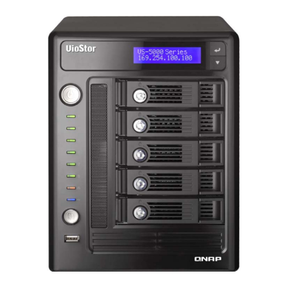
Page 9: Hardware Illustration
Hardware Illustration 1. One touch copy button 2. USB 2.0 3. LED indicators: USB, Status, HDD1, HDD2, HDD3, HDD4, HDD5, LAN 4. Power button 5. Select button 6. Enter button 7. Power connector 8. Giga LAN x 2 9. USB 2.0 x 4 10. -
Page 10: Chapter 2. Install The Viostor
Chapter 2. Install the VioStor Pre-installation Notice Before installing the VioStor, please make sure the following items are ready: Network connection devices Network cameras are configured The computer for configuring VioStor Hard disks 1 Philips screwdriver ... - Page 11 Security Settings of the Web Browser Please make sure the security level of the IE browser in Internet Options is set to Medium or lower.
-
Page 12: Install The Hardware
Before you start to use the VioStor, please install the hardware and configure the system. Install the Hardware Please follow the steps below to install the hardware: Take out the disk trays. Install a hard disk on each tray. Make sure the disk holes match the holes at the base of the disk tray and lock the disk with four screws. - Page 13 Insert the disk trays to VioStor. Push the disk trays to the end. Connect the network cable. Connect the power cord to the VioStor and plug in the power cord to the wall socket.
-
Page 14: System Configuration
System Configuration Install the Finder Execute the product CD, the following menu is shown. Click “Install Finder”. - Page 15 Follow the instructions to install the Finder. If you are using Windows XP SP2 or above, the following screen will be shown. Click “Unblock”. The Finder detects the VioStor in the network and prompts you to perform quick setup. Click “Yes” to continue. Note: If the VioStor is not found, click “Refresh”...
- Page 16 The default administrator name and password are as below: Use name: admin Password: admin Note: Please make sure all the network cameras are configured and connected to the network. The quick configuration page will be shown. Click "Continue" and follow the instructions to finish the configuration.
- Page 17 Click "Start installation" to execute the quick configuration. The quick configuration is completed and you can start to use the VioStor. Click “Start Monitoring” to view the live video from the cameras or click “Close” to return to the system administration home page.
- Page 18 The first time you connect to the server, please install the ActiveX. Follow the instructions to install the ActiveX. When the live video is displayed and the recording indicator is shown, you have successfully installed the VioStor.
-
Page 19: Chapter 3. Start To Use The Viostor
Chapter 3. Start to Use the VioStor When you have installed the VioStor and other hardware, and connected it to the network, you can use the browser in your PC to connect to the VioStor. It is recommended to use Microsoft Internet Explorer 6.0 for browsing. - Page 20 Enter the user name and password to login the VioStor. Default User name: admin Default Password: admin To view the live video, you must install the ActiveX control. Follow the instructions to install it.
-
Page 21: Monitoring Page
Monitoring Page When you have successfully logged in the VioStor, the monitoring page is shown. Select the display language. You can start to configure the system settings and use the monitoring and recording functions of the server. Server name View monitoring Adjust channel... - Page 22 grant access right to the users. Help: View the system online help. Logout: Logout the VioStor. Snapshot: Take a snapshot on the selected camera. When the picture is shown, right click the picture to save it to the computer. Manual recording: Enable or disable manual recording on the selected camera.
- Page 23 recording. The default path for storing snapshots is the “Snapshot” folder under My Documents in your computer. If the snapshot time is inconsistent with the actual time that the snapshot is taken, it is caused by the network environment but not a system error. Click the event notification icon to view the event details, enable or disable the alert sound or clear the event logs.
-
Page 24: 3.2.1 Live Video Window
3.2.1 Live Video Window If the camera is properly configured, you can see the current video from the remote network camera. If your camera supports pan and tilt functions, you can click on the video window directly to adjust the viewing angle. If the camera supports zooming, you can use a wheel mouse to adjust the zooming distance by scrolling the wheel. -
Page 25: 3.2.2 Camera Status
3.2.2 Camera Status The camera status is indicated by the icons shown below: Icon Camera Status Scheduled or continuous recording is in process This camera supports audio function This camera supports PT function Manual recording is enabled The alarm input 1 of the camera is triggered and recording is in process The alarm input 2 of the camera is triggered and recording is in process The alarm input 3 of the camera is triggered and recording is in process Motion detection recording is in process... -
Page 26: 3.2.4 Display Mode
3.2.4 Display Mode By changing the display mode, you can adjust the visual effects when viewing video of single or multiple cameras. Single channel mode Picture-in-Picture mode 4-channel mode 6-channel mode 8-channel mode 9-channel mode 10-channel mode Multi-channel mode Adjust window size Sequential mode Full screen 3.2.5 PTZ Camera Control Panel... -
Page 27: Chapter 4. Playback The Video Files
Chapter 4. Playback the Video Files To playback recording video of the VioStor is very easy to use. The VioStor provides an intuitive web interface to search and play recording files, no extra software installation is necessary. In addition, you can use network file services to access the recorded video files directly. - Page 28 Connect to Server for Playback Click "Play by Time" The following dialog will be displayed. Configure servers: Add: Add a server. Modify: Modify a server. Remove: Remove a server. Auto: Auto-search servers. Default settings: Enter the default user name and password for all newly added servers.
- Page 29 Play the Video Files 1.Click "Add files" 2.Browse and select the files to play. 3.The playlist will be shown. Click "Play" to start playing. Quad-view Playback Quad-view playback allows you to find the video more quickly. You can check the video of four different cameras or time periods simultaneously.
- Page 30 Express Quad View Playback: Divide the selected time equally into four playback views Select only one camera, and check the option "Divide the selected time period equally into all the playback windows to play". Click "OK".
- Page 31 Express Quad View Playback: Load four consecutive cameras to play Play the video files recorded by four IP cameras simultaneously.
-
Page 32: Access The Recording Data
Access the Recording Data You can access the recording data on the VioStor by the following network services: Windows Network Neighborhood (SMB/CIFS) Web File Manager (HTTP) FTP Server (FTP) Note: 1. To access the video file by these protocols, you must enter the user name and password with the administrator access right. -
Page 33: Windows Network Neighborhood (Smb/Cifs)
4.2.1 Windows Network Neighborhood (SMB/CIFS) You can access recorded files by the SMB/CIFS protocol, which is popularly used in Windows system. You can connect to the recording folder by either: On the web-based playback interface, click “SMB”. In Windows XP, run “\\VioStorIP\” from the Start menu. For example, if your VioStor ... -
Page 34: Ftp Server (Ftp)
4.2.3 FTP Server (FTP) You can access the recording data by FTP: On the web-based playback interface, click “FTP”. In Windows Internet Explorer, enter “ftp://username:password@VioStorIP/”. For example, enter “ftp://admin:admin@172.17.26.154/” if the IP address of your VioStor is 172.17.26.154. -
Page 35: Chapter 5. System Administration
Chapter 5. System Administration To login VioStor system configuration page, please login the monitoring page as an administrator and click The System Administration home page will be shown as below: If the system is not configured yet, the Quick Configuration page will be open to guide you through the setup steps first. -
Page 36: Quick Configuration
If there are questions, click on the help button on the top right hand corner. The functions of the buttons are described below: Return to monitoring page Playback recorded video View On-line help Log out Quick Configuration Please follow the instructions on the web page to configure VioStor. Note: All changes to the settings will be effective only when the last step is applied. - Page 37 Step 3. Enter the date, time, and time zone of the server. Step 4. Enter the IP address, subnet mask and default gateway of the server.
- Page 38 Step 5. Select the disk configuration to initialize the disk volume for the first time configuration. All data on the disk(s) will be deleted.
- Page 39 Step 6. Initialize IP camera setting. Select the camera model; enter the camera name and IP address of the camera, and the user name and password to login the camera. You can also enable or disable recording on each camera, test connection to the cameras and then click Save to apply the changes. Click “Search”...
- Page 40 After completing the settings, click “Start Installation” to apply the changes and initialize the system. Congratulations! The quick configuration is completed and you can start to use the VioStor. Click “Start Monitoring” to view the live video from the cameras or click “Close” to return to the system administration home page.
-
Page 41: System Settings
System Settings You can configure the basic system settings including server name, date & time, and view the system settings. 5.2.1 Server Name Enter the name of the VioStor. The server name is 14 characters long at maximum, which supports alphabets, numbers, and hyphen (-). The server does not accept names with space or names in pure number. - Page 42 Synchronize with an Internet time server automatically You can enable this option to update the date and time of the system automatically with specified NTP (Network Time Protocol) server. Enter the IP address or domain name of the NTP server, e.g. time.nist.gov, time.windows.com. Then enter the time interval for adjusting the time.
-
Page 43: View System Settings
5.2.3 View System Settings You can view the system settings, e.g. server name, on this page. -
Page 44: Network Settings
Network Settings You can configure the WAN and LAN settings, DDNS service, file service, host access control, protocol management and view the network settings in this section. 5.3.1 TCP/IP Configuration The VioStor provides two ports that you can configure failover, load balancing, or standalone functions. - Page 45 Load balancing Load balancing enables the network resources to spread between two or more network interfaces to optimize network transfer and enhance system performance. It operates on layer 3 protocol (IP, NCP IPX) only. Multicast/ broadcast and other non-routable protocols, e.g. NetBEUI, can only be transferred via the main network port.
- Page 46 Standalone The standalone option allows you to assign different IP settings for each network port. The VioStor can be accessed by different workgroups in two different subnets. However, when this function is enabled, failover does not work. You can only enable DHCP server for the primary network port (LAN 1).
- Page 47 Network Transfer Rate You can select auto-negotiation (default), 1000 Mbps, or 100 Mbps. It is recommended to use the default setting that the server will determine network speed automatically. Obtain IP address settings automatically via DHCP If your network supports DHCP, VioStor will use DHCP protocol to retrieve the IP address and related information automatically.
- Page 48 to enable the VioStor as a DHCP server and allocate dynamic IP address to DHCP clients in LAN. You can set the range of IP addresses allocated by DHCP server and the lease time. Lease time refers to time that IP address is leased to the clients by DHCP server. When the time expires, the client has to acquire an IP address again.
-
Page 49: Ddns (Dynamic Domain Name) Service
5.3.2 DDNS (Dynamic Domain Name) Service The DDNS service enables users to connect VioStor via domain name directly. There is no need to memorize the lengthy IP address of the server. To enable the DDNS service, you have to register a DDNS account from a DDNS provider. Please refer to Appendix Note: The VioStor currently supports the DDNS service provided by: DynDNS (http://www.dyndns.org/) - Page 50 remote computer cannot connect to the VioStor via WAN, you can enable this function. By enabling this function, the FTP service replies the manually specified IP address or automatically detects the external IP address so that the remote computer can connect to the VioStor successfully.
-
Page 51: Host Access Control
5.3.4 Host Access Control Specify the connections to be allowed and denied to access the VioStor. Choose one of the following options to restrict access from a network or an IP address (host) to the server: Allow all connections (Default setting) Allow connection from all hosts to the server. -
Page 52: Protocol Management
5.3.5 Protocol Management To assign a specific port for accessing the VioStor by the web browser, please enable the option “Specify HTTP port number” and enter the port number. The default setting is 80. RTP (Real-time Transfer Protocol) is a standardized packet format for delivering real-time audio and video data of network cameras over the Internet. -
Page 53: View Network Settings
5.3.6 View Network Settings You can view current network settings and status of VioStor in this section. -
Page 54: Device Configuration
Device Configuration You can configure SATA disk, RAID management tool, USB disk, and UPS settings in this section. 5.4.1 SATA Disk This page shows the model, size and current status of the disk(s) installed on the VioStor. You can format and check disks, and scan bad blocks on the disks. When the SATA disks are formatted, the VioStor will create the following default share folders: record_nvr: The folder for saving regular recording files ... - Page 55 You can create the disk volume of the following type: Single Disk Volume Each disk will be used as a standalone disk. However, if a disk is damaged, all data will be lost. RAID 1 Mirroring Disk Volume RAID 1 (mirroring disk) protects your data by automatically backing up the contents of one drive onto the second drive of a mirrored pair.
- Page 56 spare disk. RAID 5 can survive 1 disk failure and system can still operate properly. When a disk fails in RAID 5, the disk volume will be in “degraded mode”. There is no more data protection at this stage. If one more disk fails, all the data will be crashed. Therefore, you must replace a new disk immediately.
-
Page 57: Raid Management Tool
5.4.2 RAID Management Tool RAID management tool allows you to carry out capacity expansion, RAID migration, or spare drive configuration with the original drive data reserved. Expand capacity This function enables drive capacity expansion by replacing the drives in a configuration one by one. -
Page 58: Usb Disk
Add spare drive in RAID 5 Remove spare drive in RAID 5 For detailed operation, please click the “Description” button on the management interface to view the detailed operation instructions. 5.4.3 USB Disk The VioStor supports USB disks for backup storage. Connect the USB device to the USB port of the server, when the device is successfully detected, the details are shown on this page. -
Page 59: Ups
UPS Model Select the UPS model on the list. If your UPS is not available on the list, please contact the distributor or the technical support of QNAP. IP Address of UPS If you select “APC UPS with SNMP Management”, please enter the IP address of the UPS. -
Page 60: User Management
User Management The server can be accessed by multiple users. For easier management and better control of users’ access right, you have to organize users, user groups and their access right control. Note: The server supports up to 32 users (including system default users). You can create new users when necessary. -
Page 61: Create User
5.5.1 Create user User Name The user name cannot be pure number. It must not exceed 32 characters. It is case-insensitive and supports double-byte characters, such as Chinese, Japanese, and Korean except: " / \ [ ] : ; | = , + * ? < > ` ' Password The password is case-sensitive and can be 16 characters long at maximum. -
Page 62: Edit User
5.5.2 Edit User Select a user on the list and click Edit. You can change the password, assign system administration and camera access control. However, the user name cannot be changed. 5.5.3 Delete User To delete a user, select a user on the list and click “Delete”. Click “OK”... -
Page 63: Camera Settings
Camera Settings You can configure network camera, recording, schedule, alarm, and advanced settings. 5.6.1 Camera Configuration Please follow the steps below to configure the network cameras. Select a camera number. Select a camera model. Enter the camera name. Enter the IP address or domain name of the camera. Enter the user name and password to login the camera. -
Page 64: Recording Settings
5.6.2 Recording Settings Select a camera on the list and configure the recording resolution, frame rate, and quality. You can also enable manual recording. Click “Apply” to save the settings. Resolution: Select the recording resolution. Frame rate: Adjust the frame rate for recording. Note that the frame rate of the camera may be affected by the traffic of the network. -
Page 65: Schedule Settings
All the settings will not take effect until you click “Apply”. When applying changes, recording operation will stop for a while (maximum 1 minute) and then restart. 5.6.3 Schedule Settings You can select continuous recording or scheduled recording. The default setting is continuous recording. -
Page 66: Alarm Settings
5.6.4 Alarm Settings You can enable alarm recording of the cameras. The recording will be triggered by alarm input of the camera or motion detected by the camera. When you enable the option “Activate alarm recording only on selected schedule”, alarm recording will be activated only when alarm input is triggered or motion is detected within the preset schedule. -
Page 67: Advanced Settings
5.6.5 Advanced Settings You can configure advanced recording settings in this section. Maximum period for each recording file: Configure the maximum length of each recording file (maximum 15 min). When the available storage is less than…GB: Select the action to take when the ... - Page 68 Pre/Post Alarm Recordings Start recording video…second(s) before the event occurs: Enter the number of seconds to start recording before an event occurs. Stop video recording…second(s) after the event ends: Enter the number of seconds to stop recording after an event ends. The maximum number of seconds for the above settings is 300, i.e.
-
Page 69: System Tools
System Tools System Tools enable you to optimize the system maintenance and management. You can set alert notification, restart or shut down the server, configure hardware settings, system update, back up/ restore/ reset settings, set E-map and do ping test. 5.7.1 Alert Notification Enter the e-mail address of the administrator and the IP address of the SMTP server. -
Page 70: Restart/ Shut Down
5.7.2 Restart/ Shut Down Follow the steps below to restart or shut down the server. Go to “System Tools” > “Restart/ Shutdown”. Click “Restart” to reboot the server or “Shut Down” to turn off the server. -
Page 71: Hardware Settings
5.7.3 Hardware Settings You can enable or disable the hardware functions of the server. Enable configuration reset switch By enabling this option, you can press the reset button for 5 seconds to reset the administrator password and system settings to default. Note: The configuration reset switch is enabled by default. - Page 72 To use this function, please follow the steps below: Set the number of days that the latest recordings should be backed up. If 3 days are entered, the recordings of today, yesterday and the day before yesterday will be backed up. Connect a USB storage device, e.g.
-
Page 73: System Update
Failed to do so may cause the system unable to start up. Note: If the system is running properly, you do not need to update the firmware. QNAP is not responsible for any forms of data loss caused by improper or illegal system update. -
Page 74: Backup/ Restore/ Reset Settings
5.7.5 Backup/ Restore/ Reset Settings To backup all the settings, including user accounts, server name and network configuration etc., click “Backup” and select to open or save the setting file. To restore all settings, click “Browse” to select a previously saved setting file and click ... -
Page 75: Remote Replication
Remote Replication You can use the remote replication feature to copy the recording data of the local VioStor to a remote QNAP network attached storage (NAS, TS-509). The remote QNAP NAS is hereafter referred to as “the remote storage device”. - Page 76 Configure the backup data, remote backup server settings, and backup schedule of the remote storage device in sequential order. Enable remote replication (support multiple choices) In the above example, the system only copies the alarm recording data of the latest 3 days to the remote storage device.
- Page 77 Configure your remote storage server Note: It is recommended to execute the “Remote host testing” function to verify the connection to the remote storage device is successful. Configure the remote replication schedule For example, to enable the system to copy recording data automatically to remote storage device at 01:15 every Monday, please do the following: Check the box “Replication Schedule”, select “Weekly”, enter 01 Hour: 15 minute, and select “Monday”.
- Page 78 When the above options are all checked, the system executes remote replication immediately. It first judges if there are extra files on the remote location that are different from the local source. If yes, the extra files will be removed. After that, the system executes recording data backup and verifies if the free space of the internal hard disk drive is less than 4GB.
-
Page 79: Hard Disk Smart
5.7.7 Hard Disk SMART This page enables users to monitor hard drive health, temperature, and usage status by the hard disk S.M.A.R.T. mechanism. Select the hard drive and you can view the following information by clicking the corresponding buttons. Field Description Summary Displays the hard drive smart summary and the latest test result. -
Page 80: E-Map
5.7.8 E-map You can upload an E-map to VioStor to illustrate the location of the cameras. To upload an E-map, click “Browse” and select the E-map file. Then click “Upload”. You can change the caption for the E-map and click “Apply”. After uploading the E-map, click “Test”... -
Page 81: Logs & Statistics
Logs & Statistics 5.8.1 System Event Logs The server can store 10,000 recent event logs, including warning, error, and information messages. In case of system malfunction, event logs (only in English) can be retrieved to analyze system problems. Click “Save” to save the logs as csv file. Click “Delete” to clear all logs. 5.8.2 Surveillance Logs This page shows the surveillance logs such as camera connection, motion detection, and... -
Page 82: On-Line Users List
5.8.3 On-line Users List This page shows the information of the currently active users, e.g. the user name, IP address, and login time. 5.8.4 Historical Users List This page shows the information of the users who have logged in the system including the user name, IP address, login time, and the services they have accessed etc. -
Page 83: System Connection Logs
5.8.5 System Connection Logs The logs of connections to the server via samba, FTP, AFP, HTTP, HTTPS, Telnet, and SSH are recorded in this page. You can select to start or stop logging. The file transfer performance can be slightly affected by enabling the event logging. -
Page 84: Chapter 6. System Maintenance
Chapter 6. System Maintenance This section provides a general overview on system maintenance. Reset the Administrator Password and Network Settings To reset the administrator password and network settings, press the reset button of the server for five seconds. A beep sound will be heard. After resetting the system, you can login the server with the default user name and password: Default user name: admin... -
Page 85: Power Outage Or Abnormal Shutdown
Power Outage or Abnormal Shutdown In case of power outage or improper shutdown of the server, the server will resume to the state before it is shut down. If your server does not function properly after restart, please do the following: If the system configuration is lost, configure the system again. -
Page 86: Chapter 7. Troubleshooting
Chapter 7. Troubleshooting The monitoring screen did not display. Please check the following: Check if you have installed ActiveX when logging in the monitoring page. Set the security level to “Medium” or lower in Internet Options of IE browser. Make sure VioStor is turned on and the network is correctly connected. The IP address of VioStor does not conflict with other devices in the same subnet. - Page 87 I cannot login the administration page. Please check if you have the administrator authority. Only administrators are allowed to login VioStor. The live video is not clear or smooth sometimes. The image quality may be restricted and interfered by the actual network traffic. When there are multiple accesses to the camera or the VioStor server, the image quality will be reduced.
- Page 88 Check if VioStor is turned on. Check the network connection of the computer and VioStor. Refresh QNAP Finder and check the IP address of VioStor. Make sure you have turned off all firewall software on your computer. 11. The changes to the system configurations cannot take effect.
-
Page 89: Appendix A Hard Disk Recommendation List
Appendix A Hard Disk Recommendation List The following hard disk models are verified by QNAP that are compatible with VioStor. It is recommended to use the disk models listed here. Other hard disk models that are not tested by QNAP may or may not work properly with VioStor. For more updated compatible hard disk information, please visit QNAP website at http://www.qnapsecurity.com/. - Page 90 P7K500 Deskstar Hitachi HDP725032GLA360 SATA II 7200 P7K500 Deskstar Hitachi HDP725025GLA380 SATA II 7200 P7K500 Barracuda Seagate ST3750640NS SATA II 7200 Barracuda Seagate ST3500630NS SATA II 7200 Barracuda Seagate ST3400620NS SATA II 7200 Barracuda Seagate ST3320620NS SATA II 7200 Barracuda Seagate ST3250620NS SATA II...
- Page 91 Barracuda Seagate ST3250410AS SATA II 7200 7200.10 Barracuda Seagate ST3250310AS SATA II 7200 7200.10 Barracuda Seagate ST3250820AS SATA II 7200 7200.10 Barracuda Seagate ST3200820AS SATA II 7200 7200.10 Barracuda Seagate ST3160815A SATA II 7200 7200.10 Barracuda Seagate ST3160815AS SATA II 7200 7200.10 Barracuda...
- Page 92 SE16 WD Caviar WD6400AAKS SATA II 7200 SE16 WD Caviar WD5000AAKS SATA II 7200 SE16 WD Caviar WD4000AAKS SATA II 7200 SE16 WD Caviar WD3200AAKS SATA II 7200 SE16 WD Caviar WD2500AAKS SATA II 7200 SE16 SAMSUNG Samsung Spinpoint F1 SATA II 7200 1000...
-
Page 93: Appendix Bled Indication
Appendix B LED Indication The VioStor provides LED indicators for you to indicate system status and information easily. 1.Status 2.HDD1 3.HDD2 4.HDD3 5.HDD4 6.HDD5 7.LAN 8.USB Status... - Page 94 LED Display & System Status Overview Color LED Response Description A USB device is being detected by any USB port Blinking every 0.5 Removing USB device Read/ Write (only for front USB) Backup to external USB/eSATA disk is Blue in process USB device is ready (only for front panel USB) Front panel USB copy complete...
-
Page 95: Appendix C Dynamic Domain Name Registration
Appendix C Dynamic Domain Name Registration The VioStor supports DDNS service provided by DynDNS. You can go to DynDNS website http://www.dyndns.org/ to register a dynamic domain name. Configure and activate DDNS service to enable the Internet users to access your VioStor via this dynamic domain name. - Page 96 Registration Procedure Please follow the steps below to register a dynamic domain name. This guide is for reference only. If there are any changes, please refer to the instructions or documents on the web site. Open the browser and connect to http://www.dyndns.com/. Click “Create Account” to begin registration.
- Page 97 Select to accept the terms of service. Configure the mailing lists if necessary. Then click “Create Account”. When your account is successfully created, a confirmation message will be sent to your e-mail address. Please follow the instructions in the e-mail to activate your account within 48 hours.
-
Page 98: Appendix D Product Specifications
Appendix D Product Specifications Software Specification Video Display Mode 1, 4, 6, 8, 9, 10, 12,16, 20, Picture-in-Picture, Sequential mode Recording Cameras Up to 20 Number Compression Format Motion JPEG/ MPEG 4 (depends on the IP camera) Video Setting Resolution, Quality, Frame Rate E-map Upload E-map (JPEG) Recording... - Page 99 Multi-IP setting: The NVR can serve different network groups in two different subnets Utility Software QNAP Finder: Discovery and quick setup for NVR Security Operation System Linux-embedded, free from PC crash and virus attack Record of the users currently logged on and previously logged on...
- Page 100 MPEG-4 format (up to 20 channels): Dual core CPU 2.8 GHz or above For higher surveillance performance, please select more advanced PC models. Memory 1 GB or above Operation System Microsoft® Windows® XP/ Vista(32-bit) Web Browser Internet Explorer 6.0 or later Network Interface 10/100 Mbps or above View Resolution...
- Page 101 K-Lock security slot for theft prevention Reserved VGA interface for maintenance RS-232 RS-232 x1 12cm quiet cooling fan (12V DC) Certification CE, FCC, VCCI, BSMI *Designs and specifications are subject to change without notice. Please contact QNAP for updated information.
-
Page 102: Appendix E Compatible Network Camera List
Appendix E Compatible Network Camera List VioStor-P Series: All other trademarks mentioned herein are the property of their respective companies. Designs and specifications are subject to change without notice. Panasonic Panasonic BB-HCM580 Panasonic BB-HCM581 Panasonic BB-HCM527 Panasonic BB-series Panasonic BB-HCM531 Panasonic BB-HCM511 Panasonic BB-HCM515 Panasonic BB-HCM547... - Page 103 SONY SNC-Z20 SONY SNC-DM110 Arecont Vision Arecont AV 1300M Arecont AV 2100M Arecont Vision IP Cameras Arecont AV 3130/3100 Arecont AV 5100M (for VioStor-5000 series) Arecont AV 8180 (for VioStor-5000 series) Canon Canon VB-C300 Canon VB-C300 series Canon VB-C300B Canon VB-C50iR...
- Page 104 IQEYE 703 IQEYE 705 IQEYE 752 IQEYE 753 IQEYE 755 IQEYE 802 IQEYE 803 IQEYE 805 IQEYE 811 IQEYE 852 IQEYE 853 IQEYE 855 Mobotix Mobotix M12M-IT D43 Mobotix M12D-IT-DNight D43N43 Mobotix M12M-Web D43 Mobotix M12M-Secure D43 Mobotix M12M-Secure N43 Mobotix M12D-Secure D22D135 Mobotix M12D-Secure D43D135 Mobotix IP Cameras...
- Page 105 ACTi ACM5711 ACTi ACM1311 ACTi ACM143X ACTi ACM3211 ACTi ACM3311 ACTi ACM3001 ACTi ACM4100 ACTi ACM5001 ACTi CAM5XXX ACTi ACD2100 ACTi ACD2200 ACTi Video Server ACTi SED2140 ACTi SED2120 Toshiba Toshiba IK-WB12 Toshiba IP Cameras Toshiba IK-WB21 Note: To use SONY SNC-DM110 IP camera, please update the firmware to 2.7.0 or later versions.
- Page 106 VioStor-A Series: All other trademarks mentioned herein are the property of their respective companies. Designs and specifications are subject to change without notice. Axis Axis 206 Axis 206M Axis 207 Axis 207W Axis 207M/ 207MW Axis 209FD/ 209FD-R Axis 210 Axis 210A/ 211A Axis 211/211W Axis 211M...
- Page 107 Arecont AV 3130/3100 Arecont AV 5100M (for VioStor-5000 series) Arecont AV 8180 (for VioStor-5000 series) Canon Canon VB-C300 Canon VB-C300 series Canon VB-C300B Canon VB-C50iR Canon VB-C50i Canon VB-C50 series Canon VB-C50FSi Canon VB-C50Fi IQeye IQEYE 510 IQEYE 511 IQEYE 701...
- Page 108 Mobotix M12D-Secure N43N135 Mobotix D12D-Secure Mobotix M22M-IT Mobotix M22M-Secure Mobotix M22M-Secure-Night Mobotix M22M-Secure-CSVario SANYO SANYO VCC-P450/ VCC-P470 SANYO IP Cameras SANYO VCC-PT490/ PT500 ACTi ACTi ACM123X ACTi ACM34XX ACTi ACM4200 ACTi ACM56XX ACTi ACM7411 ACTi ACM5711 ACTi ACM1311 ACTi IP Cameras ACTi ACM143X ACTi ACM3211 ACTi ACM3311...
- Page 109 the firmware to 2.7.0 or later versions. To use the MPEG4 function of the Axis IP cameras, please update the firmware to 2.6.0 (3108) or later versions. To use Mobotix or IQeye IP cameras, please update the firmware to 2.6.0 (3108) or later versions.
- Page 110 Vivotek SD7151 Vivotek VS 3102 Vivotek Video Server Vivotek VS 3100P Vivotek VS7100 Arecont Vision Arecont AV 1300M Arecont AV 2100M Arecont Vision IP Cameras Arecont AV 3130/3100 Arecont AV 5100M (for VioStor-5000 series) Arecont AV 8180 (for VioStor-5000 series)
- Page 111 D-link D-Link DCS-2120 D-Link DCS-3220/3220(G) D-Link DCS-3420 D-link IP Cameras D-Link DCS-5220 D-Link DCS-5300/5300G D-Link DCS-6620/6620G IQeye IQEYE 510 IQEYE 511 IQEYE 701 IQEYE 702 IQEYE 703 IQEYE 705 IQEYE 752 IQEYE 753 IQeye IP Cameras IQEYE 755 IQEYE 802 IQEYE 803 IQEYE 805 IQEYE 811...
- Page 112 Mobotix M22M-Secure Mobotix M22M-Secure-Night Mobotix M22M-Secure-CSVario LevelOne LevelOne FCS-1010/ WCS-2010 LevelOne FCS-1030/ WCS-2030 LevelOne FCS-1040/ WCS-2040 LevelOne IP Cameras LevelOne FCS-1060/ WCS-2060 LevelOne FCS-1070/ WCS-2070 LevelOne FCS-3000 LevelOne FCS-3021 GANZ GANZ ZN-D2024 GANZ ZN-PT304L GANZ IP Cameras GANZ ZN-PT304WL GANZ ZN-YH305 GANZ Video Server GANZ ZV-S306 ACTi...
- Page 113 Please update the firmware to 2.7.0 or later versions. To use Mobotix or IQeye or GANZ IP cameras, please update the firmware to 2.6.0 (3108) or later versions. For the information of supported camera models, please visit QNAP Security website at http://www.qnapsecurity.com/.
-
Page 114: Appendix F Configuration Examples
Appendix F Configuration Examples Environment 1: VioStor, IP Camera, and monitoring PC are all in the same network Network Surveillance Installation for SOHO and SMB IP Address VioStor 192.168.1.1 192.168.1.100 Camera 1 192.168.1.101 Camera 2 192.168.1.102 Camera 3 192.168.1.103 In the example, just add the camera to the VioStor by entering the cameras’ IP address. - Page 115 Environment 2: The VioStor and the IP camera are installed behind the router, while the monitoring PC is located remotely IP Address Mapped port in router VioStor 192.168.1.1 8000 Camera 1 192.168.1.101 8001 Camera 2 192.168.1.102 8002 Camera 3 192.168.1.103 8003 Router public IP 219.87.144.205...
- Page 116 From Forward to 219.87.144.205:8000 192.168.1.1:80 219.87.144.205:8001 192.168.1.101:80 219.87.144.205:8002 192.168.1.102:80 219.87.144.205:8003 192.168.1.103:80 Step 2. Add camera to the VioStor by entering the IP address of the camera in the “IP Address” settings, and the public IP address of the router and the mapped ports of the camera to the “WAN IP Address”...
- Page 117 Environment 3: The VioStor and the IP camera are all located remotely IP Address VioStor 219.87.144.205 Camera 1 61.62.100.101 Camera 2 61.62.100.102 Camera 3 61.62.100.103 In this example, just add the camera to the VioStor by adding its IP address to the “IP Address”...
- Page 118 Environment 4: The VioStor and the IP camera are installed behind the router IP Address VioStor 1 192.168.1.101 VioStor 2 192.168.1.102 VioStor 3 192.168.1.103 Router public IP 219.87.145.205 In the example, to allow a PC which is located remotely to access each VioStor via FTP, you need to: Step 1.
-
Page 119: Technical Support
Technical Support QNAP provides dedicated online support and customer service via instant messenger. You can contact us by the following means: Website: http://www.qnapsecurity.com/ MSN: q.support@hotmail.com SKYPE: qnapskype...
Need help?
Do you have a question about the VioStor-5000 Series and is the answer not in the manual?
Questions and answers