QNAP VioStor User Manual
Network video recorder
Hide thumbs
Also See for VioStor:
- User manual (387 pages) ,
- User manual (235 pages) ,
- User manual (352 pages)
Table of Contents
Advertisement
Quick Links
Download this manual
See also:
User Manual
Advertisement
Table of Contents

Subscribe to Our Youtube Channel
Related Manuals for QNAP VioStor


Summary of Contents for QNAP VioStor
- Page 1 VioStor NVR Network Video Recorder User Manual (Version: 4.0.5) © 2013. QNAP Systems, Inc. All Rights Reserved.
- Page 2 This user manual (version 4.0.5) is applicable for the VioStor NVR firmware version 4.0.5 only. If the VioStor NVR is running an older firmware version, please refer to the previous versions of the user manuals.
- Page 3 Important Notice Reading instructions Please read the safety warnings and user manual carefully before using this product. Power supply This product can only be used with the power supply provided by the manufacturer. Service Please contact qualified technicians for any technical enquires. Do not repair this product by yourself to avoid any voltage danger and other risks caused by opening this product cover.
- Page 4 Regulatory Notice FCC STATEMENT This equipment has been tested and found to comply with the limits for a Class B digital This equipment has been tested and found to comply with the limits for a Class B digital This equipment has been tested and found to comply with the limits for a Class B digital device, pursuant to Part 15 of FCC Rules device, pursuant to Part 15 of FCC Rules.
-
Page 5: Table Of Contents
Table of Contents TABLE OF CONTENTS ............................. 5 SAFETY WARNING ............................9 CHAPTER 1. INTRODUCTION ......................10 ............................. 10 VERVIEW ........................11 ARDWARE LLUSTRATION 1.2.1 VS – 12164 / 12156 / 12148 / 12140U-RP Pro+ ............11 1.2.2 VS – 12164 / 12156 / 12148 / 12140U-RP Pro............12 1.2.3 VS –... - Page 6 Edit a Map Name ........................97 4.3.4 Delete a Map Set or an E-map ..................97 4.3.5 Indicate IP Cameras on an E-map ................... 98 4.3.6 Enable/Disable Event Alert ....................100 QNAP S ........103 EMOTE ONITORING FROM URVEILLANCE LIENT FOR INDOWS CHAPTER 5.
- Page 7 6.3.3 File Services ........................... 145 6.3.4 Host Access Control......................146 6.3.5 Protocol Management ......................147 6.3.6 View Network Settings ....................... 148 ........................149 EVICE ONFIGURATION 6.4.1 SATA Disk ..........................149 6.4.2 RAID Management Tool ..................... 153 6.4.3 USB Disk ..........................155 6.4.4 UPS ............................
- Page 8 CHAPTER 7. SYSTEM MAINTENANCE .................... 210 ............ 210 ESET THE DMINISTRATOR ASSWORD AND ETWORK ETTINGS ..................211 OWER UTAGE OR BNORMAL HUTDOWN (RAID C ) ............211 WAPPING RIVES ONFIGURATION CHAPTER 8. LCD PANEL ........................212 CHAPTER 9. TROUBLESHOOTING ....................218 APPENDIX A DYNAMIC DOMAIN NAME REGISTRATION ............
-
Page 9: Safety Warning
Safety Warning This product can operate normally in the temperature of 0ºC–40ºC and relative humidity of 0%–90%. Please make sure the environment is well-ventilated. The power cord and devices connected to this product must provide correct supply voltage. Do not place this product in direct sunlight or near chemicals. Make sure the temperature and humidity of the environment are in optimized level. -
Page 10: Chapter 1. Introduction
Introduction Overview The QNAP VioStor NVR (hereafter referred to as the NVR or the VioStor) is the high performance network surveillance solution for network-based monitoring of IP cameras, video recording, playback, and remote data access. Up to 128 channels from multiple QNAP NVR servers can be monitored simultaneously. -
Page 11: Hardware Illustration
Hardware Illustration 1.2.1 VS – 12164 / 12156 / 12148 / 12140U-RP Pro+ 1. Power Button 2. LED Indicators: 10 GbE, Status, LAN, eSATA 3. eSATA x 2 (Reserved) 4. Gigabit LAN x 4 5. USB 2.0 x 4 6. USB 3.0 x 2 7. -
Page 12: Vs - 12164 / 12156 / 12148 / 12140U-Rp Pro
1.2.2 VS – 12164 / 12156 / 12148 / 12140U-RP Pro 1. Power button 2. LED indicators: 10 GbE, Status, LAN, eSATA Select button 3. VGA 4. Expansion slot x 1 (reserved) 5. Gigabit LAN x 4 6. USB 3.0 x 2 7. -
Page 13: Vs - 8148 / 8140 / 8132 / 8124U-Rp Pro
1.2.3 VS – 8148 / 8140 / 8132 / 8124U-RP Pro+ 1. Enter Button 2. Power Button 3. Select Button 4 . LED Indicators: 10 GbE, Status, LAN, eSATA 5. eSATA x 2 (Reserved) 6. USB 2.0 x 4 7. Gigabit LAN x 4 8. -
Page 14: Vs - 8148 / 8140 / 8132 / 8124U-Rp Pro
1.2.4 VS – 8148 / 8140 / 8132 / 8124U-RP Pro Enter button Power button Select button LED indicators: 10 GbE, Status, LAN, eSATA Expansion slot x 2 (reserved) Gigabit LAN x 2 USB 3.0 x 2 USB 2.0 x 4 10. -
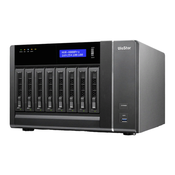
Page 15: Vs - 8148 / 8140 / 8132 / 8124 Pro
1.2.5 VS – 8148 / 8140 / 8132 / 8124 Pro+ USB 3.0 One-touch-auto-video-backup button Power button Hard drive LEDs Select button Enter button LED indicators: Status, LAN, USB, eSATA, 10 GbE Tray lock Release button Power connector Expansion slot Kensington security slot HDMI eSATA x 2 (reserved) -
Page 16: Vs - 6120 / 6116 / 6112 Pro
1.2.6 VS – 6120 / 6116 / 6112 Pro+ One-touch-auto-video-backup button USB 2.0 LED indicators: Status, LAN, USB, Power, HDD1-6 Power button Select button Enter button Power connector K-Lock Security Slot Gigabit LAN x 2 Audio In/Out (Reserved) Password & Network Settings Reset Button USB 3.0 x 2 USB 2.0 x 4... -
Page 17: Vs - 6020 / 6016 / 6012 Pro
1.2.7 VS – 6020 / 6016 / 6012 Pro One-touch-auto-video-backup button USB 2.0 LED indicators: Status, LAN, USB, eSATA, HDD1–6 Power button Select button Enter button Power connector Gigabit LAN x 2 USB 2.0 x 4 eSATA x 2 (reserved) Password &... -
Page 18: Vs - 4016 / 4012 / 4008U-Rp Pro
1.2.8 VS – 4016 / 4012 / 4008U-RP Pro One-touch-auto-video-backup button USB 2.0 LED indicators: Status, LAN, USB, eSATA, HDD1–4 Power button Power connector Gigabit LAN x 2 USB 2.0 x 4 eSATA x 2 (reserved) Password & network settings reset button... -
Page 19: Vs - 4116 / 4112 / 4108 Pro
1.2.9 VS – 4116 / 4112 / 4108 Pro+ One-touch-auto-video-backup button USB 2.0 LED indicators: Status, LAN, USB, HDD1–4 Power button Select button Enter button Power connector K-Lock Security Slot Gigabit LAN x 2 Audio In/Out (Reserved) Password & network settings reset button USB 3.0 x 2 USB 2.0 x 4... -
Page 20: 1.2.10 Vs - 4016 / 4012 / 4008 Pro
1.2.10 VS – 4016 / 4012 / 4008 Pro One-touch-auto-video-backup button USB 2.0 LED indicators: Status, LAN, USB, eSATA, HDD1–4 Power button Select button Enter button Power connector Gigabit LAN x 2 USB 2.0 x 4 eSATA x 2 (reserved) Password &... -
Page 21: 1.2.11 Vs - 2112 / 2108 / 2104 Pro
1.2.11 VS – 2112 / 2108 / 2104 Pro+ 1. One-touch-auto-video-backup button 2. USB 3.0 3. LED Indicators: LAN, HDD1, HDD2 4. Power Button 5. Power Connector 6. Gigabit LAN x 2 7. USB 2.0 x 4 8. Password & Network Settings Reset Button 9. -
Page 22: 1.2.12 Vs - 2012 / 2008 / 2004 Pro
1.2.12 VS – 2012 / 2008 / 2004 Pro One-touch-auto-video-backup button USB 2.0 LED indicators: HDD1, HDD2, LAN, eSATA Power button Power connector Gigabit LAN x 2 USB 2.0 x 2 eSATA x 2 (reserved) Password & network settings reset button Kensington security slot... -
Page 23: 1.2.13 Vs - 2008 / 2004 L
1.2.13 VS – 2008 / 2004 L One-touch-auto-video-backup button USB 2.0 LED Indicators: USB, status, HDD1, HDD2, LAN, power Power button Power connector Gigabit LAN USB 2.0 x 2 Password & network settings reset button K-Lock security slot Power cord hook... -
Page 24: 1.2.14 Vs - 1004 L
1.2.14 VS – 1004 L One-touch-auto-video-backup button USB 2.0 LED Indicators: USB, status, HDD, eSATA, LAN, power Power button Power connector Gigabit LAN USB 2.0 x 2 Password & network settings reset button K-Lock security slot eSATA Power cord hook Note: This model is designed for some projects only. -
Page 25: Chapter 2. Install The Nvr
Chapter 2. Install the NVR For the information of hardware installation, see the ‘Quick Installation Guide’ (QIG) in the product package. The QIG can also be found in the product CD-ROM or QNAP website (http://www.qnapsecurity.com). -
Page 26: Personal Computer Requirements
Personal Computer Requirements For better system performance, the computer should at least fulfill the following requirements: No. of Format Others Channels M-JPEG Intel Pentium 4 CPU, Operation system: 2.4GHz or above Microsoft Windows 8, 7, Vista MPEG-4/MxPEG/H.264 Dual core CPU, 2.0GHz Memory: 2GB or or above above... - Page 27 Security Settings of the Web Browser Please make sure the security level of the IE browser in Internet Options is set to Medium or lower.
-
Page 28: Browse Cd-Rom
Browse CD-ROM Run the product CD-ROM on a Windows PC to access the Quick Start Guide and user manual, and install codec and software utilities Finder and VioStor Player. - Page 29 VioStorPlayer: The setup program of VioStor Player, a tool to play the videos recorded by the NVR. If you failed to install VioStor Player when connecting to the playback page of the NVR by an IE browser, install the plugin from the CD-ROM.
-
Page 30: Hard Disk Drives Compatibility List
This product works with 2.5-inch and 3.5-inch SATA hard disk drives from popular hard disk brands. For the hard disk compatibility list, please visit http://www.qnapsecurity.com/pro_compatibility.asp QNAP disclaims any responsibility for product damage/malfunction or data loss/recovery due to misuse or improper installation of hard disks in any occasions for any reasons. -
Page 31: Check System Status
Check System Status LED Display & System Status Overview Color LED Status Description 1) A hard drive on the NVR is being formatted 2) The NVR is being initialized Flashes green 3) The system firmware is being updated and red 4) RAID rebuilding is in process alternately 5) Online RAID Capacity Expansion is in... - Page 32 Flashes green The hard drive data is being accessed Green The hard drive can be accessed 1) A USB device is detected 2) A USB device is being removed from the Flashes blue 3) The USB device connected to the front every 0.5 sec USB port of the NVR is being accessed 4) The NVR data is being copied to the...
- Page 33 Beep Alarm (beep alarm can be disabled in ‘System Tools’ > ‘Hardware Settings’) Beep sound No. of Times Description Short beep (0.5 sec) 1) The NVR is starting up 2) The NVR is being shut down (software shutdown) 3) The reset button is pressed 4) The system firmware has been updated Short beep (0.5 sec) The NVR data cannot be copied to the external...
-
Page 34: System Configuration
System Configuration Install Finder Run the product CD, the following menu is shown. Click ‘Install Finder’. Follow the instructions to install the Finder. Upon successful installation, run the Finder. If the Finder is blocked by the firewall, unblock it. The Finder detects the NVR servers on the local network. If the server has not been initialized, you will be prompted to perform quick setup. - Page 35 Enter the administrator name and password to perform quick setup. The default administrator name and password are as below: Use name: admin Password: admin Note: Make sure all the IP cameras are configured and connected to the network. The quick configuration page will be shown. Click ‘Continue’ and follow the instructions to finish the configuration.
- Page 36 Click ‘Start installation’ to execute the quick configuration. After the quick configuration, the NVR is ready for use. Click ‘Start Monitoring’ to view the live video from the IP cameras or click ‘Close’ to return to the home page of the system administration.
- Page 37 The first time to connect to the monitoring page of the NVR, install the ActiveX add-on. The live video from the IP cameras configured on the NVR and the recording status of each channel are shown.
-
Page 38: Chapter 3. Use The Nvr By Local Display
Chapter 3. Use the NVR by Local Display Note: This feature is supported by the VioStor Pro Series NVR only. The models include VS-12164U-RP Pro, VS-12156U-RP Pro, VS-12148U-RP Pro, VS-12140U-RP Pro, VS-8148U-RP Pro, VS-8140U-RP Pro, VS-8132U-RP Pro, VS-8124U-RP Pro, VS-8148 Pro+,... - Page 40 When the NVR is turned on, the login screen will be shown. Select the language. Enter the administrator name and password. If the NVR has not been configured, skip the login page and enter Quick Configuration (refer to Chapter 3.1). Default user name: admin Password: admin Click...
-
Page 41: Quick Configuration
Quick Configuration If the NVR has not been configured, Quick Configuration Wizard will be shown. Follow the instructions of the wizard to complete the system setup. Note: All the changes will be effective only after applying the settings in the last step. 1. - Page 42 2. Change the admin password or use the default password (admin). 3. Select to obtain the network settings automatically or enter the network settings.
- Page 43 4. Enter the date and time settings. Select to synchronize the server time with an Internet time server. To enter a domain name for the NTP server, make sure the DNS server has been correctly set up. 5. Select the disk configuration. Click ‘Disk Information’ to view the hard disk drive details.
- Page 44 6. Configure the IP camera settings. If no IP cameras have been set, try to search for the cameras on the local network. a. The cameras found will be shown. Select the IP cameras and click ‘Add’ to add the channels.
- Page 45 b. To manually add an IP camera or edit the camera settings, click c. Enter the camera settings. Click ‘Test’ to test the connection. Click ‘Remove’ to delete the camera.
- Page 46 d. To edit the recording settings, click next to ‘Recording Settings’. Define the recording settings and click ‘OK’. Digital Watermarking: Enable this option to add digital watermarks to the video files recorded to the NVR. Use the Watermark Proof utility to verify if the video files were maliciously modified.
- Page 47 7. Verify the settings and click ‘Next’ to initialize the server. 8. After the system has been initialized, the NVR is ready for use. Click ‘Start Monitoring’ to enter the monitoring screen.
-
Page 48: System Configuration
System Configuration Configuration To manage the system settings settings such as administrator password, network network and time settings, click on the monitoring screen on the monitoring screen. Note that this button (option) will be shown will be shown for administrator access only. Select the language and click the icons to configure the settings. - Page 49 Icon Description Perform quick configuration of the system. Change the administrator password to login local display. Change the network settings. Change the date and time settings. Configure the disk volume and initialize the hard disks. Configure the IP camera settings.
-
Page 50: Monitoring
Monitoring Upon successful login, the monitoring the monitoring screen will be shown. Monitor the IP cameras, onitor the IP cameras, change the display mode, enable or disable change the display mode, enable or disable manual recording, control the the PTZ cameras, and so on. - Page 51 Icon Description Monitor: Enter the monitoring page. Playback: Enter the playback page. Configuration: Enter the system configuration page; allows admin access only. Hide left panel: Hide the panel on the left of the monitoring page. Show left panel: Show the panel on the left of the monitoring page. Options: Configure the event notification settings, video window display settings, screen resolution, etc.
- Page 52 Event notification: When the alarm recording is enabled and an event is detected, this icon will be shown. Click this icon to view the alert details. The alert sound can be turned on or off. To clear all the logs, click ‘Clear All’.
- Page 53 PTZ Control Panel The term ‘PTZ’ stands for ‘Pan/Tilt/Zoom’. If the IP camera supports PTZ, use the control panel on the NVR to adjust the viewing angel of the IP camera. These functions are available depending on the camera models. Please consult the camera's documentation for details.
- Page 54 Display Mode The NVR supports various display modes for monitoring. Click the correct icon to switch the display mode. Icon Description Full screen Single-channel mode 4-channel mode 6-channel mode 8-channel mode 9-channel mode 10-channel mode 12-channel mode 16-channel mode Select the display page number Sequential mode.
- Page 55 Live View Screen Upon successful configuration of the IP cameras, enter the monitoring screen to view the live video from the cameras. If the camera supports pan and tilt functions, click the channel on the screen and adjust the viewing angle with a mouse. If zooming is supported, scroll the mouse wheel to zoom in or zoom out the video.
- Page 56 Camera Status The camera status is indicated by the icons shown below: Icon Camera Status Scheduled or continuous recording is in process This IP camera supports audio function This IP camera supports PTZ function Manual recording is enabled The recording triggered by advanced event management (‘Camera Settings’ > ‘Alarm Settings’...
- Page 57 Connection Message When the NVR fails to display the video of an IP camera, a message will be shown in the channel window to indicate the status. Message Description Connecting If the IP camera is located on remote network or the Internet, it may take some time to establish the connection to the camera.
- Page 58 Dewarp panomorph images: for the specific camera models with panomorph lens Before using this feature, you need to select the ‘Enable panomorph support’ option in the recording settings page. Right click the channel and enable the function. After that, you can select Mount type, including wall, ceiling, and floor and then select Dewarping mode, including Perimeter mode, Quad mode, and PTZ mode.
- Page 59 Options To configure advanced monitor settings, click The following options are provided under the ‘General’ tab. Event Notification: When ‘Enable alert for all surveillance events’ option is enabled and a surveillance event is triggered, the alert icon will be shown on the monitoring page instantly.
- Page 60 The following options are provided under the ‘Video’ tab. Highlight the video window when an event is triggered: The video window will flash if an event is triggered. Display unauthorized channels: Select this option to show the channels that the user does not have access right to monitor.
- Page 61 The NVR detects the resolution settings supported by the connected monitor and selects the most appropriate setting automatically. To change the screen resolution, click ‘Settings’ under the ‘Screen’ tab. After configuring the resolution settings, the monitoring screen will be shown. If the monitor model cannot be detected, the NVR will provide the options 1920*1080, 1400*1050, 1280*1024, 1024*768.
-
Page 62: Video Playback
Video Playback The videos on the NVR can be played can be played by the local display. To use this feature, To use this feature, click on the monitoring screen. Most of the icons on the playback screen are the same as those Most of the icons on the playback screen are the same as those Most of the icons on the playback screen are the same as those on the monitoring screen. - Page 63 Playback Settings: Play, pause, stop, reverse play a video file, or select to play the previous or next file. When playing a video, use the scroll bar to adjust the playback speed or click the digital zoom icon to zoom in or zoom out the video. Right click the IP camera channel and select the following options: a.
- Page 64 Dewarp panomorph images: for the specific camera models with panomorph lens Before using this feature, you need to select the ‘Enable panomorph support’ option in the recording settings page. Right click channel and enable the function. After that, you can select Mount type, including wall, ceiling, and floor and then select Dewarping mode, including Perimeter mode, Quad mode, and PTZ mode.
-
Page 65: Video Conversion & Export
Video Conversion Video Conversion & Export The NVR supports converting the video files to AVI format and saving the files to an supports converting the video files to AVI format and saving the files to an supports converting the video files to AVI format and saving the files to an external USB storage device. - Page 66 2. Select the IP camera and the recording type. 3. Specify the start and end time of the video files. 4. Enter the file name of the video file. 5. Click ‘OK’ to convert the video files to an AVI file and save them to the external USB storage device.
-
Page 67: Chapter 4. Remote Monitoring
Note: QNAP Surveillance Client is a client application developed by QNAP Systems, inc., used to locally or remotely access QNAP NVR servers for performing video monitoring and playback functions. Users can find and download this application under the ‘Utility’ section of the QNAP Security website at http://www.qnapsecurity.com/download.asp... -
Page 68: Connect To The Nvr
To view the live video by Internet Explorer, please add the NVR IP address to the list of trusted sites. While accessing NVR via IE, it will be prompted to install the ActiveX add-on. To view the live video by Google Chrome, Mozilla Firefox or QNAP Surveillance Client on Windows PC, please visit http://www.qnapsecurity.com/download.asp to download and install QNAP Surveillance Client for Windows first. - Page 69 To view the live video on Mac, please visit http://www.qnapsecurity.com/download.asp to download and install QNAP Surveillance Client for Mac.
-
Page 70: Monitoring Page
Monitoring Page Upon successful login, the monitoring page will be shown. Select the display language. Start to configure the system settings and use the monitoring and recording functions of the server. Adjust display mode Server/ camera tree You can also drag the control panel to the position you like. - Page 71 The NVR supports multi-display mode. (This function can only be used when the computer or the host is connected to multiple monitors.) Multi-server monitoring: Up to 128 channels from multiple QNAP NVR servers can be monitored. E-map: Upload E-map(s) and indicate the locations of the IP cameras.
- Page 72 Turn on/off the audio support for the monitoring page. For more information about the compatibility of this feature, please visit http://www.qnap.com/NVR/CompatibilityX01.html. Two-way audio (optional): Turn on/off the two-way audio support for the monitoring page. For more information about the compatibility of this feature, please visit http://www.qnap.com/NVR/CompatibilityX01.html.
- Page 73 Note: Enabling or disabling the manual recording feature will not affect the scheduled or alarm recording. By default, the snapshots are saved in ‘My Documents’ or ‘Documents’> ‘Snapshots’ on Windows. If the snapshot time is inconsistent with the actual time that the snapshot is taken, it is caused by the network environment but not a system error.
- Page 74 k. Dewarp panomorph images: for the specific camera models with panomorph lens Before using this feature, you need to select the ‘Enable panomorph support’ option in the recording settings page. Right click the channel and enable the function. After that, you can select Mount type, including wall, ceiling, and floor and then select Dewarping mode, including Perimeter mode, Quad mode, and PTZ mode.
- Page 75 To configure other monitoring options, right click a channel and select ‘Properties’. Streaming: Always stream from the server: Select this option to stream the audio and video data from the NVR. If the computer cannot connect to the IP cameras, select this option to allow the NVR to stream the data;...
- Page 76 Display Mode: Fit image to window: Select this option to fit an image to the browser window. Specify to keep the aspect ratio or not when resizing an image. Display image in original size: Select this option to display an image in its original size if it is smaller than the browser window.
- Page 77 Video Resolution: Specify to adjust the resolution automatically or use a fixed resolution. To adjust the resolution automatically, the NVR will select the resolution setting* which best fits the size of the IE browser window. Note that ‘Stream from network camera’ will not be available if the IP camera does not support streaming from camera or video resolution configuration.
-
Page 79: Live Video Window
4.2.1 Live Video Window The live videos of the IP cameras configured on the NVR are shown on the monitoring page. Click the channel window to use the features supported by the IP camera, e.g. digital zoom or pan/tilt/zoom. Camera Status The camera status is indicated by the icons shown below: Icon Camera Status... - Page 80 Connection Message When the NVR fails to display the video of an IP camera, a message will be shown in the channel window to indicate the status. Message Description Connecting If the IP camera is located on a remote network or the Internet, it may take some time to establish the connection to the camera.
-
Page 81: Display Mode
4.2.2 Display Mode The NVR supports different display modes for viewing the monitoring channels. Single 9-channel 12-channel 6-channel Page Sequential channel mode mode mode number mode settings* 4-channel 8-channel 10-channel Multi-channel Sequential mode mode mode mode mode *You can configure the sequential interval in the sequential mode settings. 4.2.3 PTZ Camera Control Panel The term ‘PTZ’... - Page 82 Digital zoom: Select a channel and click this button to enable the digital zoom function. This function can also be enabled by right clicking the display window of the PTZ camera. Press button to zoom in or button to zoom out. You can also use the mouse wheel to operate the digital zoom function.
-
Page 83: Multi-Server Monitoring
4.2.4 Multi-server Monitoring Follow the steps below to use the multi-server monitoring feature of the NVR. Click ‘Server List’ on the monitoring page. a. Click ‘Auto Detect’ to search for the NVR on the LAN and add the server to the server list. -
Page 84: Monitor Settings
4.2.5 Monitor Settings To configure advanced monitor settings, click The following options are provided under the ‘General’ tab. Event Notification: When ‘Enable alert for all surveillance events’ option is enabled and a surveillance event is triggered, the alert icon will be shown on the monitoring page instantly. - Page 85 The following options are provided under the ‘Video’ tab. Video Streaming Stream from the server: If the IP camera cannot be connected from the computer, select this option and the video will be streamed from the NVR. This option does not require extra port mapping configuration;...
- Page 86 The following options are provided under the ‘Snapshot’ tab. Snapshot: Specify the location where the snapshots are saved and the image format (JPEG or BMP). Show timestamp and camera name: Show the timestamp and the camera name on the snapshot. Save the snapshot as it is displayed: Select this option to save the snapshot as it is displayed on the window.
-
Page 87: Auto Cruising
4.2.6 Auto Cruising The auto cruising feature of the NVR is used to configure the PTZ cameras to cruise according to the preset positions and the staying time set for each preset position. To use the auto cruising feature, follow the steps below. 1. - Page 88 4. Click the number buttons to view the preset positions of the PTZ camera. When this button is clicked, the name of the corresponding preset position is shown on the ‘Preset Name’ drop-down menu.
- Page 89 5. Add: To add a setting for auto cruising, select the ‘Preset Name’ from the drop-down menu and enter the staying time (interval, in seconds). Click ‘Add’. 6. Update: To change a setting on the list, highlight the selection. Select another preset position from the drop-down menu and/or change the staying time (interval).
- Page 90 8. After configuring the auto cruising settings, select the option ‘Enable auto cruising’ and click ‘OK’. The NVR will start auto cruising according to the settings. Note: The default staying time (interval) of the preset position is 5 seconds. Enter 5–999 seconds for this setting.
-
Page 91: E-Map
E-map The E-map feature of the NVR is provided to for users to upload electronic maps to the system to indicate the locations of the IP cameras. Users can drag and drop the camera icons* to the E-map and enable event alert to receive instant notification when an event occurs to the IP camera. - Page 92 An E-map example is shown below. The NVR provides a default E-map. Add or remove the E-maps whenever necessary. Note: Login as an administrator to edit and view the E-map. Enable/Disable Enable/Disable event E-map E-map edit mode alert on E-map Tree menu of E-maps and IP cameras...
-
Page 93: Icons And Description
4.3.1 Icons and Description Icon Description Enable E-map edit mode. E-map edit mode in use. Click this icon to disable the edit mode. Add a map. Edit the name of a map. Remove a map or a camera icon. Event alert not in use. Click this icon to enable event alert on the E-map. -
Page 94: Add A Map Set Or An E-Map
4.3.2 Add a Map Set or an E-map To add a map set or an E-map to indicate the locations of the IP cameras, click enable Edit mode. A list of IP cameras configured on the NVR will be shown on the left. Click ‘Default’ and then to add an E-map. - Page 95 Enter the map name and select the file. The E-map must be in JPEG format. Click ‘OK’. The E-map will be shown.
- Page 96 To add one or multiple E-maps, e.g. office1 and office2, under an E-map, e.g. floor1, click the E-map icon of floor1 and then click to add the E-maps one by one. The icon of floor1 will be changed to when more than one E-map is added. To add another E-map of the same level of floor1, select ‘Default’...
-
Page 97: Edit A Map Name
4.3.3 Edit a Map Name To edit the name of an E-map, select the E-map and click . Enter the new name and click ‘OK’. To change the picture of the E-map, delete the E-map and add the new file. 4.3.4 Delete a Map Set or an E-map To delete an E-map, select the map... -
Page 98: Indicate Ip Cameras On An E-Map
4.3.5 Indicate IP Cameras on an E-map After uploading the E-maps, drag and drop the IP camera icons to the E-map(s) to indicate the camera location. The camera name will appear under the E-map on the top left column. When an icon of a fixed body or fixed dome IP camera is dropped to the E-map, right click the camera icon and adjust the icon direction. - Page 99 To save the changes made to the E-maps, click to exit the Edit mode. When clicking an E-map or an IP camera on the left, the E-map or the E-map with the camera icon will be shown on the right immediately. The selected camera icon will be highlighted with a blue bracket When double clicking a camera icon on an E-map, whether or not Edit mode is enabled, the IP camera will be shown in single-channel mode on the monitoring screen.
-
Page 100: Enable/Disable Event Alert
4.3.6 Enable/Disable Event Alert To enable event alert on an E-map, click... - Page 101 When an event occurs to an IP camera on the E-map, the camera icon will flash and indicate the event type. The E-map with the IP camera on which an event is triggered will be shown immediately*. Double click the camera/alert icon and the monitor screen will switch to display the alert camera channel in single-channel view on the monitor screen automatically.
- Page 102 The event type occurred to an IP camera he event type occurred to an IP camera can be identified by the camera icon by the camera icon on an E-map. Icon Description Description A moving object has been detected A moving object has been detected The alarm input 1 of the IP camera has been triggered The alarm input 1 of the IP camera has been triggered The alarm input 1 of the IP camera has been triggered...
-
Page 103: Remote Monitoring From Qnap Surveillance Client For Windows
Remote Monitoring from QNAP Surveillance Client for Windows 1. After installing QNAP Surveillance Client for Windows, click Start → All Programs → QNAP → Surveillance → Surveillance Client to open QNAP Surveillance Client for Windows. 2. The following window will be shown. -
Page 104: Chapter 5. Play Video Files
To play the recording files by Internet Explorer, please add the NVR IP address to the list of trusted sites. While accessing NVR via IE, it will be prompted to install the ActiveX add-on. To play the recording files by Google Chrome, Mozilla Firefox or QNAP Surveillance Client on Windows PC, please visit http://www.qnapsecurity.com/download.asp download and install QNAP Surveillance Client for Windows. -
Page 105: Playback Page
Playback Page Click the playback button on the monitoring page or the system administration page. The playback page will be shown. You can search and play the video files on the NVR servers. To return to the monitoring page, click . - Page 106 The following table consists of the icons and their descriptions in the playback page. Icons Description Configure the options such as playing mode, snapshot settings, and digital watermark Multi-view mode (up to 16-view mode) Convert the video files on the NVR to AVI files Audio (optional): Turn on/off the audio support Take a snapshot of the video Search recording files by IVA...
- Page 107 Next time interval Digital zoom: Enable/Disable digital zoom. When digital zoom is enabled ( ), you can click to use digital zoom function. Stop Play/pause a video file Last frame Next frame Reverse play Play the video at 1/16x, 1/8x, 1/4x, 1/2x, 1x, 2x, 4x, 8x, 16x speed Control all views: Control the playback settings of all the playback windows...
-
Page 108: Play Video Files From Nvr
5.1.1 Play Video Files from NVR Follow the steps below to play the video files on the remote NVR servers. 1. Drag and drop camera(s) from the server/camera tree to the respective playback window(s) to select the channel(s) for playback. 2. - Page 109 Right click the channel on the playback page. The following functions are available depending on the IP camera model. Dewarp fisheye images: for Vivotek FE8171V/ FE8172 Right click the channel and enable the function. After that, you can select Mount type, including wall, ceiling, and floor and then select Dewarping mode, including Panorama (Full View), Panorama (Dual View), and Rectangle.
-
Page 111: Intelligent Video Analytics (Iva)
5.1.2 Intelligent Video Analytics (IVA) The NVR supports intelligent video analytics for video data search. The following features are supported: Motion detection: Detects the movements of the objects in the video. Foreign object: Detects new objects in the video. Missing object: Detects missing objects in the video. Out of focus: Detects if the camera is out of focus. - Page 112 3. Configure the IVA settings for video search. Select the detection mode: Motion detection, Foreign object, Missing object, Out of focus, or Camera occlusion. Multiple options can be selected. Adjust the sensitivity for object detection. Adjust the time interval for detecting the foreign objects and missing objects. If a foreign object appears or a missing object disappears for a period of time which is longer than the time interval, the NVR will record the event.
- Page 113 Define the detection zone. Mouse over the edge of the red zone and use the mouse to define the detection zone. Click ‘Select all’ to highlight the entire area. Define the object size for detection. Use the mouse to drag the yellow zone to define the minimum object size for detection.
- Page 114 • Ignore objects with width or height less than this setting: Enable this option to ignore all the objects smaller than the yellow zone. Enable/Disable other options for video search. • Pause when found: Enable this option and the video search will stop when a video file matching the search criteria is found.
- Page 116 Other options: • Double click an entry on the search result dialog to play the video. The player will play the video starting from 15 seconds before the event to 15 seconds after the event. • Right click an entry on the search result dialog to export the video (AVI format) and save it to the computer.
-
Page 117: Convert Nvr Videos To An Avi File
5.1.3 Convert NVR Videos to an AVI File To convert the video files on the NVR to an AVI file and export the file to the local PC in the playback page, please follow the steps below. Note: The playback access rights of the IP cameras are required to use this feature. 1. - Page 118 4. All the video files that met the search criteria will be converted to an AVI file.
-
Page 119: Export Video Files With Digital Watermark
Digital watermarks can be added to the exported videos and snapshots in the playback page. The watermark cannot be removed and can only be verified by the QNAP Watermark Proof software. To use digital watermarking in the playback page, follow the steps below. -
Page 120: Play Video Files In Qnap Surveillance Client For Windows
Play Video Files in QNAP Surveillance Client for Windows 1. Click Start → All Programs → QNAP → Surveillance → Surveillance Client to open QNAP Surveillance Client for Windows. 2. The following window will be shown. 3. Enter IP address/port, user name and password to log into the NVR. -
Page 121: Watermark Proof
Watermark Proof The Watermark Proof utility is installed automatically along with the QNAP Surveillance Client for Windows. From the Windows Start menu, select ‘All Programs’ > ‘QNAP’ > ‘Surveillance’ to locate ‘Watermark Proof’. Run Watermark Proof. The following window will be shown. - Page 122 Click to check the files and view the proof result. When ‘Stop when watermark error is detected’ is selected, the checking process will stop if a failed file is detected. Otherwise the program will check all the files selected. If a video file has been modified, or is not exported with digital watermark, or not an NVR video file, the proof result will be shown as ‘Failed’.
-
Page 123: Access The Recording Data
Access the Recording Data The recording data on the NVR can be accessed by the following services: Microsoft Networking (SMB/CIFS) Web File Manager (HTTP) FTP Server (FTP) Note: To access the video files by these protocols, enter the user name and password with the administrator access right. -
Page 124: Microsoft Networking (Smb/Cifs)
5.4.1 Microsoft Networking (SMB/CIFS) Access the video files by the SMB/CIFS protocol on Windows OS. Run \\NVR_IP from the Windows Start menu. For example, if the NVR IP is 10.11.19.27, enter \\10.11.19.27. 5.4.2 Web File Manager (HTTP) To access the recording data in the NVR by a web browser, go to http://NVR IP Address/cgi-bin/filemanager/filemanager.cgi?folder=/home/httpd/cgi-bin/filemanager/sh are&ComboBox=ON&lang=eng and login as an administrator. -
Page 125: Ftp Server (Ftp)
5.4.3 FTP Server (FTP) Access the recording data by FTP: In Windows Internet Explorer, enter ftp://username:password@NVRIP. For example, enter ftp://admin:admin@172.17.26.154 if the NVR IP is 172.17.26.154. -
Page 126: Chapter 6. System Administration
Chapter 6. System Administration To enter the system configuration page of the NVR, login the monitoring page as an administrator and click Upon successful login, the monitoring channels, connection and recording status, and the network bandwidth of the NVR will be shown on the ‘Advanced Mode’ page. View the settings by ‘Traditional Mode’. - Page 127 If the NVR is has not been configured yet, the Quick Configuration page will be shown. Follow the instructions to finish the setup. The functions of the buttons on the configuration page are described below: Return to the monitoring page Playback the videos View the on-line help Logout the NVR...
-
Page 128: Quick Configuration
Quick Configuration Follow the instructions to configure the NVR. Note: All the changes will be effective only after clicking ‘Start installation’ in the last step. - Page 129 Enter the server name. The server name supports up to 14 characters which may include alphabets (A–Z and a–z), numbers (0–9), and dash (-). Space and period (.) are not allowed. Change the administrator password or select to use the default password (admin).
- Page 130 Enter the date, time, and time zone of the server. Enter the IP address, subnet mask, and default gateway of the server.
- Page 131 Select the disk configuration. All the disk data will be cleared unless ‘Do not to set the disk configuration’ is selected.
- Page 132 Initialize the IP camera settings. Select the camera brand and model. Enter the name and IP address of the camera, and the user name and password. Enable or disable the recording function on each channel, test the connection to the IP cameras and then click ‘Save’ to apply the changes. Click ‘Search’...
- Page 133 Click ‘Start Installation’ to apply the changes and initialize the system.
- Page 134 Click ‘Start Monitoring’ to view the live video from the IP cameras or click ‘Close’ to return to the system administration home page.
-
Page 135: System Settings
System Settings Configure the basic system settings including the server name, the date & time, and view the system settings. 6.2.1 Server Name Enter the name of the NVR. The server name supports up to 14 characters which can only contain alphabets (A–Z and a–z), numbers (0–9), and dash (-). -
Page 136: Date & Time
6.2.2 Date & Time Set the date, time, and time zone. If the settings are incorrect, the following problems may occur: Incorrect time display on the video files. Incorrect time display on the event logs. Synchronize with an Internet time server automatically Enable this option to update the date and time of the NVR automatically with an NTP (Network Time Protocol) server. -
Page 137: View System Settings
6.2.3 View System Settings View the system settings such as the server name on this page. -
Page 138: Network Settings
Network Settings Configure the WAN and LAN settings, DDNS service, file service, host access control, protocol management and view the network settings in this section. 6.3.1 TCP/IP Configuration If the NVR supports a single LAN port, select one of the following options to configure the TCP/IP settings of the NVR. - Page 139 If the NVR supports two LAN ports, select to use failover, load balancing, or standalone settings. To use these features, make sure both LAN ports are connected to the network.
- Page 140 Configuration of Network Interfaces Failover (Default settings for dual LAN NVR models) Failover refers to the capability of switching over the network transfer port to the redundant port automatically when the primary one fails due to hardware or connection error to avoid network disconnection. When the primary network port resumes the connection, the network transfer will be switched over to that port automatically.
- Page 141 Load balancing Load balancing enables the network resources to spread between two or more network interfaces to optimize the network transfer and enhance the system performance. It operates on layer 3 protocol (IP, NCP IPX) only. Multicast/broadcast and other non-routable protocols such as NetBEUI can only be transferred via the main network port.
- Page 142 Standalone Assign different IP settings for each network port. The NVR can be accessed by different workgroups on two different subnets. When load balancing is enabled, failover does not work. The DHCP server can only be enabled for the primary network port (LAN 1).
- Page 143 Network Transfer Rate Select auto-negotiation (default), 1000 Mbps, or 100 Mbps. It is recommended to use the default setting that the server will determine the network speed automatically. Obtain IP address settings automatically via DHCP If the network supports DHCP, select this option to allow the NVR to retrieve an IP address and the related information automatically.
-
Page 144: Ddns (Dynamic Domain Name) Service
6.3.2 DDNS (Dynamic Domain Name) Service The DDNS service enables the users to connect to the NVR by the domain name directly. There is no need to memorize the lengthy IP address of the server. To enable the DDNS service, register a DDNS account from a DDNS provider. Please refer to Appendix A details. -
Page 145: File Services
6.3.3 File Services Enable the SMB/CIFS file service, Web File Manager, and FTP service to access the video files. These settings are enabled by default. If the NVR is installed behind the router, enable FTP port mapping to allow the users from the external network to connect to the NVR via FTP (please refer to Appendix Passive FTP Port Range... -
Page 146: Host Access Control
6.3.4 Host Access Control Specify the connections to be allowed or denied to connect to the NVR. Choose one of the following options to restrict the access from a network or an IP address (host) to the server: Allow all connections (Default setting) Allow the connection from all the hosts to the server. -
Page 147: Protocol Management
6.3.5 Protocol Management To connect to the NVR by a specific HTTP port number, enable the option ‘Specify HTTP port number’ and enter the port number. The default setting is 80. RTP (Real-time Transfer Protocol) is a standardized packet format for delivering real-time audio and video data of the IP cameras on the Internet. -
Page 148: View Network Settings
6.3.6 View Network Settings View the current network settings and the status of the NVR in this section. -
Page 149: Device Configuration
Device Configuration Configure the SATA disk, RAID management tool, USB disk, and the UPS settings in this section. 6.4.1 SATA Disk This page shows the model, size and current status of the hard disk drive(s) installed on the NVR. Other options include formatting the hard disks and viewing the status, and scanning the hard drive bad blocks. - Page 150 Click the icons on the ‘SATA Disk’ page to format the hard disk drive(s). Disk Configuration Applied NVR Models Single disk volume All models RAID 1, JBOD (just a bunch of disks) 2-bay models or above RAID 5, RAID 6, RAID 5+hot spare 4-bay models or above RAID 6+hot spare 5-bay models or above...
- Page 151 Single Disk Volume Each hard disk drive is used as a standalone disk. If a disk is damaged, all the data will be lost. JBOD (Just a bunch of disks) JBOD is a collection of hard disk drives that does not offer any RAID protection. The data are written to the physical disks sequentially.
- Page 152 RAID 5 Disk Volume The data are striped across all the drives in a RAID 5 array. The parity information is distributed and stored across each drive. If a member drive fails, the array enters degraded mode. After installing a new drive to replace the failed one, the data can be rebuilt from other member drives that contain the parity information.
-
Page 153: Raid Management Tool
6.4.2 RAID Management Tool *This function is not supported by the VS-1004L. The RAID management tool supports capacity expansion, RAID migration, or spare drive configuration with the original drive data reserved. Expand capacity This function enables capacity expansion of a RAID configuration by replacing the member drives one by one. - Page 154 Configure spare drive This function enables adding or removing a spare drive from a RAID 5 configuration. The options available are: Add a spare drive to a RAID 5 configuration Remove a spare drive from a RAID 5 configuration For detailed operation instructions, click ‘Comment’ on the management interface.
-
Page 155: Usb Disk
6.4.3 USB Disk The NVR supports data backup to the external USB storage devices. Connect the USB storage device to the USB port of the NVR, when the device is successfully detected, the details will be shown. -
Page 156: Ups
UPS Model Select the UPS model on the list. If the UPS is not available on the list, please contact the distributor or QNAP technical support. IP Address of UPS If ‘APC UPS with SNMP Management’ is selected, enter the IP address of the UPS. -
Page 157: User Management
User Management The NVR supports secure user access right management. A user can be defined as an administrator, a system manager, or a general user and given different rights of monitoring, playback, and system administration. Note: The NVR supports up to 32 users (including the system default users). The NVR supports 3 types of users: 1. - Page 158 3. user The general users have only the rights of monitoring and video playback. They have no administration authority. Please refer to Chapter 6.5.4 for more details.
-
Page 159: Create User
6.5.1 Create user User Name The user name must be 1 to 32 characters in length. It supports alphabets (A-Z), numbers (0-9), and underscores (_). It is case-insensitive and supports double-byte characters, such as Chinese, Japanese, and Korean but cannot be a pure number or contain the following characters: “... -
Page 160: Edit User
6.5.2 Edit User Select a user on the list and click ‘Edit’. Change the password; assign the rights of system administration and camera access to the user. However, the user name cannot be changed. 6.5.3 Delete User To delete a user, select the user on the list and click ‘Delete’. Click ‘OK’ to confirm. Note: The system administrator (admin, supervisor, sysmgr) cannot be deleted. -
Page 161: User Access Rights Comparison
6.5.4 User Access Rights Comparison The NVR supports three types of users including system administrator, system manager, and general user. The default system administrators are ‘admin’ and ‘supervisor’ who cannot change one another’s password, user type, and access rights to the IP cameras. Note 1: The user can delete his/her account Note 2: The user can change his/her password administrator... - Page 162 administrator system manager user Other Other Rights admin supervisor sysmgr system User administrators managers Change the camera access control of supervisor Change the camera access control of other administrators Create sysmgr Default Create other system manager accounts Delete sysmgr Delete other system No (Note 1) manager accounts Change the password of...
- Page 163 administrator system manager user Other Other Rights admin supervisor sysmgr system User administrators managers Change the user type of normal users Change the camera access control of normal users System administration Yes Monitoring Default Playback Default Open data encryption password...
-
Page 164: Camera Settings
Camera Settings Configure the IP camera, recording, schedule, alarm, and advanced settings. 6.6.1 Camera Configuration Please follow the steps below to configure the IP cameras. Select a camera number. Select the camera brand. Select the camera model. Enter the camera name. Enter the IP address or domain name of the camera. - Page 165 Note: All the settings will not take effect until ‘Apply’ is clicked. When applying the changes, the recording operation will stop for a while (maximum 1 minute) and then restart. Click ‘Search’ to search for the IP cameras on the local network. Select a channel for the IP camera and click ‘Add’...
- Page 166 Note: The NVR only supports JPEG CGI command interface, but does not guarantee the compatibility with all the IP camera brands.
-
Page 167: Recording Settings
6.6.2 Recording Settings Select a camera on the list and configure the recording resolution, frame rate, and quality. Enable audio recording, manual recording, recording data retention, real-time digital watermarking, and auto snapshot settings. Click ‘Apply’ to save the settings. Video compression: Choose a video compression format for the recording. Resolution: Select the recording resolution. - Page 168 visit http://www.immervision.com/en/security/security_partners/security_partners_2.ph Manual recording: To allow manual activation and deactivation of manual recording function on the monitoring page, enable this option. Real-time digital watermarking: Enable this option to add digital watermarks to the video files as soon as they are recorded to the NVR. Use the Watermark Proof utility to verify if the video files were maliciously modified.
- Page 169 Note: Starting and stopping manual recording will not affect scheduled or alarm recording tasks. They are independent processes. All the settings will not take effect until ‘Apply’ is clicked. When applying the changes, recording will stop for a while (maximum 1 minute) and then restart. The settings of the snapshot folder are global settings which will be applied to all the channels.
-
Page 170: Schedule Settings
6.6.3 Schedule Settings Select continuous recording or scheduled recording. The default setting is continuous recording. To set up a recording schedule, select a camera number on the list. Then select the date and time and click ‘Add’. Click ‘Apply’ to save the settings for the particular IP camera or click ‘Apply to all cameras’... -
Page 171: Alarm Settings
6.6.4 Alarm Settings The NVR provides ‘Traditional Mode’ and ‘Advanced Mode’ for alarm settings. Select ‘Traditional Mode’ to use the standard alarm settings in response to the alarm events. To use advanced event management, select ‘Advanced Mode’. Traditional Mode Select a channel (IP camera/video server) on the list and configure the alarm settings. The video recording will be activated when the alarm input of the selected channel is triggered or a moving object is detected. - Page 172 Note: All the settings will be effective after clicking ‘Apply’. When applying the changes, the current recording process will stop for a while (maximum 1 minute) and then restart. To avoid blocking by the firewall, the IP cameras or the video servers configured for alarm recording must be located on the same subnet as the NVR.
- Page 173 Advanced Mode: The advanced mode consists of the event and action sections. Define the action to take for each event triggered on the IP cameras or the video servers connected to the NVR. To configure the advanced event management by the ‘Advanced Mode’, select an event type on the left channel list and configure the actions to take on the right.
- Page 174 Events: The events supported by the NVR are classified as camera events (motion detection, alarm input, camera disconnection), NVR events (recording failure), and external events (user-defined events). Note: The camera events available depend on the features supported by the IP cameras or video servers.
- Page 175 The NVR supports the following event types. Before specifying the action settings, select the events to manage and configure the settings. (1) Alarm input This option allows the NVR to trigger an action when the alarm input of the IP camera or the video server is triggered.
- Page 176 (2) Motion detection This option allows the NVR to trigger an action when a moving object is detected by the IP camera or the video server. Select ‘Camera event’ from the ‘Event List’. Locate the channel and click ‘Motion Detection’. Next, click the edit button ( enable this option, configure the settings, and click ‘Apply’.
- Page 177 (4) Connection failure This option allows the NVR to trigger an action when the IP camera or the video server is disconnected. Select ‘Camera Event’ from the ‘Event List’. Locate the channel and click ‘Connection Failure’. After that, define the action on the right (discussed in the later sections).
- Page 178 (6) External event (user-defined events) To create a self-defined event on the NVR, select ‘User-defined Event’ under ‘External event’ on the ‘Event List’. Then click the + button. Enter the event name, for example, ‘door’. After creating an event, click the event name and define the action on the right (discussed in the later sections).
- Page 179 Event schedule settings: When editing an event (not including camera disconnection, NVR events, and external events), click ‘Set Schedule’ to define when the alarm settings will be active. To create a new schedule, select ‘New’ and enter the schedule name. The schedule supports maximum 25 characters (double-byte characters, spaces, and symbols are allowed).
- Page 180 Actions: The NVR supports different actions which can be activated when the selected events are triggered on the IP cameras or the video servers. The actions include video recording, email alert, SMS alert, buzzer, PTZ camera control, alarm output, and logic output. Button Description Add an action:...
- Page 182 (1) Recording Select the channels (IP cameras or video servers) which will start recording when an event occurs. The following options are also available: (i) Enter the time (in seconds) the recording should be executed after the event is triggered. (ii) Start recording when the event starts and stop recording when the event ends.
- Page 183 (2) Camera control Configure the PTZ camera to adjust to the preset position for monitoring or act according to the HTTP URL entered when an event is triggered. Select a preset position from the drop-down menu or enter the HTTP URL. Click ‘Select from the list’...
- Page 184 (3) Alarm output Select to activate the alarm device connected to the IP camera when an event is triggered. The following options are available: Enter the number of second(s) the alarm device will be active when the event is triggered. (ii) Activate the alarm device when the event starts and stop the alarm device when the event ends.
- Page 185 (4) Email To receive an instant email alert when an event is triggered, enter the SMTP settings. Multiple email addresses can be entered as the recipients. Snapshots of multiple channels (IP cameras/video servers) can be attached to the alert emails. Click ‘Select from the list’...
- Page 186 (5) SMS To allow the system administrator to receive an instant SMS alert when an event is triggered, enter the SMS server settings. The default SMS service provider is Clickatell. To add other SMS service providers, click ‘Add’ and enter the provider's name and the URL template text.
- Page 187 (6) Buzzer Enable the buzzer when an event is triggered. The following options are also available: Enter the time (in seconds) the buzzer will sound when the event is triggered. (ii) Execute the buzzer when the event starts and stop the buzzer when the event ends.
- Page 188 (7) User-defined Action Add a self-defined action when an event is triggered. Enter the login account and password, IP address, port, and the HTTP URL of other surveillance devices to manage the devices such as fire protection devices, power controller, and air conditioning control.
-
Page 189: Advanced Settings
6.6.5 Advanced Settings Configure the advanced recording settings in this section. Maximum period for each recording file: Specify the maximum length of each recording file (maximum 15 min). When the available storage is less than…%: Specify if the NVR should overwrite the oldest recordings or stop recording when the available storage capacity is less than the specified percentage of the total storage capacity. - Page 190 Pre-/Post-alarm Recordings Start recording video…second(s) before the event occurs: Enter the number of seconds to start the recording before an event occurs. Stop video recording…second(s) after the event ends: Enter the number of seconds to stop the recording after an event ends. The maximum number of seconds for the above settings is 300, i.e.
-
Page 191: System Tools
System Tools The System Tools help optimize the system maintenance and management. Set the alert notification, restart or shut down the server, configure the hardware settings, update the system firmware, back up/restore/reset the system settings, set the E-map, and run the ping test. -
Page 192: Smsc Settings
6.7.2 SMSC Settings Configure the SMSC (Short message service centre) settings to send the SMS text messages to the particular mobile phone numbers when an event takes place on the NVR. The default SMS service provider is Clickatell. Add an SMS service provider by selecting ‘Add SMS Provider’... -
Page 194: Restart/Shut Down
6.7.3 Restart/Shut Down Follow the steps below to restart or shut down the server. Go to ‘System Tools’ > ‘Restart/Shutdown’. Click ‘Restart’ to reboot the server or ‘Shut Down’ to turn off the NVR. -
Page 195: Hardware Settings
6.7.4 Hardware Settings Enable or disable the hardware functions of the NVR. Enable the configuration reset switch By enabling this option, press the reset button for 5 seconds to reset the administrator password and system settings to default. Note: The configuration reset switch is enabled by default. When this option is disabled, keep the password safely. - Page 196 Enable front video backup button The NVR supports direct copy of the recording data on the NVR to the connected USB device via the USB port. Set the number of days that the videos are recorded to copy to the device.
-
Page 197: System Update
Before doing so, make sure the product model and the firmware version are correct. Note: If the NVR is running properly, it may not be necessary to update the firmware. QNAP is not responsible for any forms of data loss caused by improper or illegal system update. -
Page 198: Back Up/Restore/Reset Settings
6.7.6 Back up/Restore/Reset Settings To back up all the settings, including the user accounts, the server name and the network configuration, click ‘Back up’ and select to open or save the setting file. To restore all the settings, click ‘Browse’ to select a previously saved setting file and click ‘Restore’. To reset all the settings to default, click ‘Reset’. -
Page 199: Remote Replication
Remote Replication Use the remote replication feature to copy the recording data of the local NVR to a remote QNAP network attached storage (NAS). The remote QNAP NAS is hereafter referred to as ‘the remote storage device’. Note: Before using this function, make sure the Microsoft networking service of the remote storage device is enabled, and the corresponding path and user access right have been correctly configured. - Page 200 2. Enable remote replication (support multiple choices) In the above example, the NVR only copies the alarm recording data of the latest 3 days to the remote storage device. Select ‘Enable remote replication’ to activate this feature. The NVR executes automatic backup of the recording data to the remote storage device according to the settings.
- Page 201 4. Configure the remote replication schedule For example, to enable the NVR to copy the recording data automatically to the remote storage device at 01:15 every Monday, please do the following: Select ‘Replication Schedule’, select ‘Weekly’, enter 01 Hour: 15 minute, and select ‘Monday’.
- Page 202 6. The NVR displays the latest 10 remote replication records. In the above example: When the status is shown as ‘Failed (Remote access error)’: Check if the remote storage device is running or the network settings are correct. When the status is shown as ‘Failed (An internal error occurred)’: View the hard drive status of the NVR or view the Event Logs.
-
Page 203: Hard Disk Smart
6.7.8 Hard Disk SMART Monitor the health, temperature, and status of the hard disk drives by the S.M.A.R.T. (Self-Monitoring, Analysis, and Reporting Technology). Enable ‘Issue notification when the disk reaches maximum operation time set below’. When the operation time of each installed hard drive exceeds the value, the system will record the event to the log. -
Page 204: Ping Test
6.7.9 Ping Test To test the connection to an IP address, enter the IP address and click ‘Test’. -
Page 205: Advanced System Settings
6.7.10 Advanced System Settings Set the timeout period to log off the users from the configuration page of the NVR when the idling time has reached. To allow guest access to the monitoring screen of the NVR by local display, select ‘Enable anonymous access’. -
Page 206: Logs & Statistics
Logs & Statistics 6.8.1 System Event Logs The NVR can save maximum 10,000 recent event logs, including warning, error, and information messages. In case of system malfunction, the event logs (only in English) can be retrieved to analyze the system problems. Click ‘Save’... -
Page 207: Surveillance Logs
6.8.2 Surveillance Logs This page shows the surveillance logs such as camera connection, motion detection, and camera authentication failure. Note: The logs are only available in English. -
Page 208: On-Line Users List
6.8.3 On-line Users List This page shows the information of the currently active users, e.g. the user name, IP address, and login time. Note: The logs are only available in English. 6.8.4 Historical Users List This page shows the information of the users who have logged in the system including the user name, IP address, login time, and the services they have accessed etc. -
Page 209: System Connection Logs
6.8.5 System Connection Logs The connection logs to the NVR by Samba, FTP, AFP, HTTP, HTTPS, Telnet, and SSH are recorded on this page. Select to start or stop the logging. The file transfer performance may be slightly affected by enabling the event logging. Note: The logs are only available in English. -
Page 210: Chapter 7. System Maintenance
Chapter 7. System Maintenance This section provides a general overview of the system maintenance. Reset the Administrator Password and Network Settings To reset the administrator password and the network settings, press the reset button of the server for five seconds. A beep sound will be heard. After resetting the system, login the server with the default user name and password: Default user name: admin Password: admin... -
Page 211: Power Outage Or Abnormal Shutdown
Power Outage or Abnormal Shutdown In case of power outage or improper shutdown of the server, the server will resume to the state before it is shut down. If the server does not function properly after the restart, please do the following: If the system configuration were lost, configure the system again. -
Page 212: Chapter 8. Lcd Panel
Chapter 8. LCD Panel * This section is applicable to the NVR models with an LCD panel only. The NVR provides a handy LCD panel for users to perform the disk configuration and view the system information. When the NVR has started up, the server name and the IP address will be shown: N V R 5 F 4 D E 3 1 6 9 . - Page 213 For example, when five hard drives have been installed, the LCD panel shows: C o n f i g . D i s k s ? R A I D 5 → Press the ‘Select’ button to browse more options, e.g. RAID 6. Press the ‘Enter’...
- Page 214 View the system information by the LCD panel When the LCD panel shows the server name and the IP address, press the ‘Enter’ button to enter the Main Menu. The Main Menu consists of the following items: 1. TCP/IP 2. Physical disk 3.
- Page 215 Physical disk In Physical disk, the following options are available: Disk Info Back to Main Menu The disk info shows the temperature and the capacity of the hard disk drive. D i s k : 1 T e m p : 5 0 °...
- Page 216 System This section shows the system temperature and the rotation speed of the system fan. C P U T e m p : ° S y s T e m p : ° S y s F a n : 8 6 5 R P M Shut down Use this option to turn off the NVR.
- Page 217 System Messages When the NVR encounters system error, an error message will be shown on the LCD panel. Press the ‘Enter’ button to view the message. Press the ‘Enter’ button again to view the next message. S y s t e m E r r o r ! P l s .
-
Page 218: Chapter 9. Troubleshooting
Chapter 9. Troubleshooting The monitoring screen did not display. Please check the following: a. Check if the ActiveX add-on has been installed when logging in the monitoring page of the NVR. Set the security level to ‘Medium’ or lower in Internet Options of the IE browser. - Page 219 The E-map cannot be displayed correctly. Please check the file format. The NVR supports E-map in JPEG only. I cannot find the NVR by the QNAP Finder. a. Check if the NVR has been turned on. b. Connect the local PC and the NVR to the same subnet.
- Page 220 e. If the NVR is not found, click ‘Refresh’ on the Finder to try again. If the problem persists, contact the technical support. 10. The changes to the system configuration did not take effect. After changing the settings on the administration page, click ‘Apply’ to apply the changes.
-
Page 221: Appendix Adynamic Domain Name Registration
Appendix A Dynamic Domain Name Registration The NVR supports the DDNS service provided by DynDNS. Configure and activate the DDNS service to enable the Internet users to connect to the NVR by this dynamic domain name. When the ISP assigns a new WAN IP address, the NVR will update the new address to the DynDNS server automatically. - Page 222 Registration Procedure Follow the steps below to register a dynamic domain name. This guide is for reference only. If there are any changes, please refer to the instructions or the documents on the web site. Visit http://www.dyndns.org. Click ‘Sign In’ and ‘Create an Account’ to register a DynDNS account.
- Page 223 A confirmation email will be sent to the registered email address. Click the link in the email to confirm the registration.
- Page 224 Click ‘Confirm Account’ and login DynDNS. Register a host name for the NVR. A host name is a unique name that identifies the server. Then click ‘Add’.
- Page 225 Activate the host name. The DDNS host name is ready for use. You can now login the NVR and set up the DDNS service.
-
Page 226: Appendix Bconfiguration Examples
Appendix B Configuration Examples Environment 1: The NVR, the IP camera, and the monitoring PC are all on the same network IP address 192.168.1.1 192.168.1.100 Camera 1 192.168.1.101 Camera 2 192.168.1.102 Camera 3 192.168.1.103 In the example, add the IP cameras to the NVR by entering the IP addresses of the IP cameras. - Page 227 Environment 2: The NVR and the IP camera are installed behind the router, while the monitoring PC is located remotely IP address Mapped port on the router 192.168.1.1 8000 Camera 1 192.168.1.101 8001 Camera 2 192.168.1.102 8002 Camera 3 192.168.1.103 8003 Router public IP 219.87.144.205...
- Page 228 To allow a remote PC to connect to the NVR and the IP cameras, do the following: Step 1. Set up the port mapping (virtual server) on the router. From Forward to 219.87.144.205:8000 192.168.1.1:80 219.87.144.205:8001 192.168.1.101:80 219.87.144.205:8002 192.168.1.102:80 219.87.144.205:8003 192.168.1.103:80 Step 2.
- Page 229 Environment 3: The NVR and the IP camera are all located remotely IP address 219.87.144.205 Camera 1 61.62.100.101 Camera 2 61.62.100.102 Camera 3 61.62.100.103 In this example, add the IP camera to the NVR by adding its IP address to the ‘IP Address’ settings.
- Page 230 Environment 4: The NVR and the IP camera are installed behind the router IP address NVR 1 192.168.1.101 NVR 2 192.168.1.102 NVR 3 192.168.1.103 Router public IP 219.87.145.205 In the example, to allow a remote PC to connect to each NVR by FTP, do the following: Step 1.
-
Page 231: Technical Support
Technical Support QNAP provides dedicated online support and customer service via instant messenger. Online Support: http://www.qnapsecurity.com/onlinesupport.asp MSN: q.support@hotmail.com Skype: qnapskype Facebook: http://www.facebook.com/pages/QNAP-Security/195448000471677 Forum: http://forum.qnapsecurity.com Technical Support in the USA and Canada: Email: q_supportus@qnap.com TEL: +1-909-595-2782 Address: 168 University Parkway, Pomona CA 91768... -
Page 232: Gnu General Public License
GNU GENERAL PUBLIC LICENSE Version 3, 29 June 2007 Copyright © 2007 Free Software Foundation, Inc. <http://fsf.org/> Everyone is permitted to copy and distribute verbatim copies of this license document, but changing it is not allowed. Preamble The GNU General Public License is a free, copyleft license for software and other kinds of works. - Page 233 For the developers' and authors' protection, the GPL clearly explains that there is no warranty for this free software. For both users' and authors' sake, the GPL requires that modified versions be marked as changed, so that their problems will not be attributed erroneously to authors of previous versions.
- Page 234 To ‘propagate’ a work means to do anything with it that, without permission, would make you directly or secondarily liable for infringement under applicable copyright law, except executing it on a computer or modifying a private copy. Propagation includes copying, distribution (with or without modification), making available to the public, and in some countries other activities as well.
- Page 235 work's System Libraries, or general-purpose tools or generally available free programs which are used unmodified in performing those activities but which are not part of the work. For example, Corresponding Source includes interface definition files associated with source files for the work, and the source code for shared libraries and dynamically linked subprograms that the work is specifically designed to require, such as by intimate data communication or control flow between those subprograms and other parts of the work.
- Page 236 When you convey a covered work, you waive any legal power to forbid circumvention of technological measures to the extent such circumvention is effected by exercising rights under this License with respect to the covered work, and you disclaim any intention to limit operation or modification of the work as a means of enforcing, against the work's users, your or third parties' legal rights to forbid circumvention of technological measures.
- Page 237 an ‘aggregate’ if the compilation and its resulting copyright are not used to limit the access or legal rights of the compilation's users beyond what the individual works permit. Inclusion of a covered work in an aggregate does not cause this License to apply to the other parts of the aggregate.
- Page 238 code work. A ‘User Product’ is either (1) a ‘consumer product’, which means any tangible personal property which is normally used for personal, family, or household purposes, or (2) anything designed or sold for incorporation into a dwelling. In determining whether a product is a consumer product, doubtful cases shall be resolved in favor of coverage.
- Page 239 for unpacking, reading or copying. 7. Additional Terms. ‘Additional permissions’ are terms that supplement the terms of this License by making exceptions from one or more of its conditions. Additional permissions that are applicable to the entire Program shall be treated as though they were included in this License, to the extent that they are valid under applicable law.
- Page 240 notice stating that it is governed by this License along with a term that is a further restriction, you may remove that term. If a license document contains a further restriction but permits relicensing or conveying under this License, you may add to a covered work material governed by the terms of that license document, provided that the further restriction does not survive such relicensing or conveying.
- Page 241 peer-to-peer transmission to receive a copy likewise does not require acceptance. However, nothing other than this License grants you permission to propagate or modify any covered work. These actions infringe copyright if you do not accept this License. Therefore, by modifying or propagating a covered work, you indicate your acceptance of this License to do so.
- Page 242 Each contributor grants you a non-exclusive, worldwide, royalty-free patent license under the contributor's essential patent claims, to make, use, sell, offer for sale, import and otherwise run, modify and propagate the contents of its contributor version. In the following three paragraphs, a ‘patent license’ is any express agreement or commitment, however denominated, not to enforce a patent (such as an express permission to practice a patent or covenant not to sue for patent infringement).
- Page 243 was granted, prior to 28 March 2007. Nothing in this License shall be construed as excluding or limiting any implied license or other defenses to infringement that may otherwise be available to you under applicable patent law. 12. No Surrender of Others' Freedom. If conditions are imposed on you (whether by court order, agreement or otherwise) that contradict the conditions of this License, they do not excuse you from the conditions of this License.
- Page 244 permanently authorizes you to choose that version for the Program. Later license versions may give you additional or different permissions. However, no additional obligations are imposed on any author or copyright holder as a result of your choosing to follow a later version. 15.
Need help?
Do you have a question about the VioStor and is the answer not in the manual?
Questions and answers