Atlas Copco Power Focus 4000 User Manual
Power focus series
Hide thumbs
Also See for Power Focus 4000:
- Quick manual (43 pages) ,
- Quick manual (92 pages) ,
- Product instructions (124 pages)
Table of Contents
Advertisement
Quick Links
Download this manual
See also:
Quick Manual
Advertisement
Table of Contents

Related Manuals for Atlas Copco Power Focus 4000


Summary of Contents for Atlas Copco Power Focus 4000
- Page 1 User guide Power Focus Atlas Copco Industrial Technique AB 9836 3123 01 Software release W10.9 SR3 Edition 18.2 2013-03...
- Page 2 Copyright Atlas Copco Tools and Assembly Systems Note! This manual can be altered without further notice. For further information log in to Atlas Copco www.atlascopco.com...
-
Page 3: Table Of Contents
Contents Contents Contents ......................... 3 General safety instructions ................11 Work area ......................11 Electrical safety ...................... 11 Personal safety ...................... 12 Service ........................13 Introduction ......................15 Revision history ...................... 15 Abbreviations ......................15 Introduction to Power Focus ................17 PF 4000 ......................... - Page 4 Contents Digital inputs ......................36 Digital outputs (relays) .................... 37 24 VDC output ......................38 4.10 I/O Bus ........................38 4.11 Remote start connector ..................39 4.12 Main power connector .................... 40 PF user interface ....................41 PF Graph ........................ 41 5.1.1 Front panel ......................
- Page 5 Contents Quick programming ....................78 Programming help ....................79 Programming ......................80 Control strategies ....................84 7.6.1 Tq con ........................84 7.6.2 Tq con/ang mon ....................... 85 7.6.3 Ang con/tq mon ....................... 85 7.6.4 Tq con/ang con (AND) / (OR) .................. 86 7.6.5 Reverse ang ......................
- Page 6 Contents 9.2.2 Creating a new Job ....................120 9.2.3 Select Job ......................122 Functions in the Job monitor ................. 124 Unlock the tool ...................... 125 Controller ......................126 10.1 Information ......................126 10.2 Configuration ......................128 10.3 Network ........................ 130 10.3.1 Cell and Net configuration ..................
- Page 7 Contents 12.4 Printer ........................178 Sync ........................181 13.1 Sync prerequisites and limitations ................ 182 13.2 Hardware configuration ..................183 13.3 Sync configuration ....................184 13.3.1 Sync members configuration ................. 184 13.3.2 Sync reference configuration ................. 185 13.4 Troubleshooting ....................187 Identifier ......................
- Page 8 Contents 16.2 Logic operators and function blocks ..............247 16.2.1 Logic gates......................247 16.2.2 Function blocks ..................... 248 16.3 Logic Configurator setup ..................251 16.3.1 Simulation ......................256 Monitors ......................259 17.1 Result Monitor ...................... 260 17.2 Job Monitor ......................262 17.3 Operator Monitor ....................
- Page 9 Contents 20.5 Reverse ang ......................298 20.6 Rotate spindle forward and Rotate spindle reverse ..........299 20.7 Home position forward and reverse ..............300 20.8 DS con ......................... 301 20.8.1 One stage ......................301 20.8.2 Two stage ......................301 20.8.3 Quick step ......................
- Page 10 Contents 22.6.1 Digital I/O ......................375 22.6.2 I/O bus ........................376 22.6.3 Tool bus ........................ 377 22.6.4 Printer ........................377 22.7 Sync ........................377 22.7.1 Programming ......................377 22.8 Identifier ........................ 378 22.8.1 Identifier setup ...................... 378 22.9 Fieldbus ........................ 379 Event codes .......................
-
Page 11: General Safety Instructions
General safety instructions General safety instructions Ensure that you read and understand all instructions. Failure to follow all the instructions listed below may result in electric shock, fire and/or serious personal injury. All locally legislated safety regulations with regard to installation, operation and maintenance must be adhered to at all times. Refer installation and servicing to qualified personnel only. -
Page 12: Personal Safety
Do not force the tool. Use the correct Atlas Copco Tensor tool for your application. The correct tool will do the Job better and more safely in a manner for which it was designed. -
Page 13: Service
Product Information for PF4000 (9836 3113 00) Product Information for PF3000 (9836 2156 for spare parts and instructions, and Atlas Copco spare part list for the tool used. There is a risk of explosion if batteries are incorrectly replaced. Replace only with the same or equivalent type recommended by the equipment manufacturer. -
Page 15: Introduction
The last part of the user guide lists the parameters and event codes used in PF. Revision history Apart from editorial updates, this manual has been revised as follows. Updates to reflect functional changes: Contact Atlas Copco for a release description for the current release. Abbreviations... - Page 16 Introduction Abbreviation Description Abbreviation Description Hertz (unit of frequency) R chart Range chart Input/Output Random Access Memory Identification Remote Access Server in.lb Inch-pound Rapid Backup Memory Infra-Red Revolutions per minute Industrial Radio Communication RS232 Serial communication link Kilo pound meter S4/S7/S9 Motor sizes in Tensor S tools Liquid Crystal Display...
-
Page 17: Introduction To Power Focus
This section includes an overview of the system, and a brief description of the options and accessories. For more information about the available system parts and their functionality, contact your Atlas Copco representative and consult the relevant user guide or catalog. - Page 18 PF 3100, PF 4000 is available in one model with two versions (Compact and Graph) that can handle all torque levels. Advanced control functions built into Power Focus 4000 prevent the operator from deviating from the required process. When it receives assembly information, the programmed Job function automatically selects the correct tightening sequence and parameters.
-
Page 19: Pf 3000/3100/3102
Introduction to Power Focus PF 3000/3100/3102 is a control system for Atlas Copco Tensor S and DS tools. is a control system for PF 3000 PF 3100 Atlas Copco Tensor ST tools (including functionality for S and DS tools). is the control system PF 3102 for Atlas Copco Tensor SL tools. -
Page 20: Rbu
RBU giving the required functionality with the chosen hardware. For a list of the current RBU functionality, contact your Atlas Copco representative. When an RBU is plugged in to an empty PF, the RBU configuration is transferred to the controller. This allows the quick installation and replacement of controllers on the assembly line. - Page 21 Introduction to Power Focus Communicate with one PF at a time via the serial connection or with a complete network of PF units via the built-in TCP/IP connection. Power Focus communicates with a range of accessories via the internal I/O bus. PF units and accessories can be combined according to the customer’s requirements.
-
Page 22: Tensor Tools
Introduction to Power Focus Tensor tools This is a brief overview of Atlas Copco Tensor tools and tool accessories. See tool specific information for a complete list of tools and options for each tool. communicates with the tightening controller systems through wireless digital communication, Tensor STB built on IRC (Industrial Radio Communication) technique. -
Page 23: Tool Accessories
Power Focus. The STwrench communicates with the tightening controller systems through wireless digital communication, built on IRC (Industrial Radio Communication) technique. 3.6.1 Tool accessories See Atlas Copco tool specific information for a list of options for each tool. 9836 3123 01 23 (428) - Page 24 Introduction to Power Focus is placed on the tool and works as a barcode reader. For more information ST scanner about the function of identifiers, see section Identifier. (General purpose I/O) is a digital input and output connector. The four buttons GPIO combined with four LED’s can each be configured as a digital input and/or digital output.
-
Page 25: Hardware Accessories
Introduction to Power Focus Hardware accessories The Power Focus concept features a number of accessories that simplify the guidance and follow-up of performed tightenings. The accessory functions can be set up using ToolsTalk PF or a PF Graph unit. The benefit of using serial bus-based accessories ( ) is that they can be connected in series, from I/O bus accessory to accessory rather than hard wiring each accessory to the Power Focus. - Page 26 Introduction to Power Focus is a socket tray with LED’s that can be used to guide the user Socket Selector through, for example, a Job sequence. When using more than one Pset it is very convenient to use a selector. When a socket is lifted, the corresponding Pset will be selected.
-
Page 27: Software Accessories
Introduction to Power Focus Software accessories 3.8.1 The ATS (Assembly Tools Software) works together with PF to complete the tightening process. The following software products are part of ATS. ToolsNet ToolsNet works together with the controllers and the selected database, MS SQL Server or Oracle to collect, store and visualize all historic tightening-related data. -
Page 28: Acta 4000
Introduction to Power Focus 3.8.2 ACTA 4000 performs a full range of functions, from simple torque checks ACTA 4000 to advanced graphic tightening analysis. It comes in different models and it is easy to upgrade. ACTA 4000 measures torque, angle, and pulses and facilitates the conduction of statistical analyses of the tightening process. -
Page 29: Connecting Devices
Connecting devices Connecting devices This section describes the connections on PF backplane. It also describes the start-up process for PF and for the tools. PF connections Backplane connections Digital input + internal 24 V DC Relays Ground Fault Interrupter (GFI) Serial #1 (RS 232) to MC-card I/O Bus #1 I/O Bus #2... -
Page 30: Rbu
Make sure that the power is switched off when connecting and disconnecting the RBU. The RBU unlocks the software and works as a backup memory for the Power Focus setup data. The pin configuration is propriety information for Atlas Copco. This connector cannot be used for other purposes. -
Page 31: Tool Connection And Start-Up
Connecting devices Message at start-up Action No message The memory areas of PF and the RBU are identical, and the checksums are correct. Clear / RBU / PF The memory areas of PF and the RBU show correct checksums, but they are different. -
Page 32: Tensor Stb
Connecting devices 4.3.2 Tensor STB For connection of the wireless Tensor STB, ensure the correct tool connection is configured before starting the pairing procedure. See PF parameters under Tool > Configuration > Connection and Tool > . For instructions on the pairing procedure, see Tensor STB documentation. Configuration >... -
Page 33: Wireless Tools
Connecting devices To do a start-up configuration, follow these steps: 1. Reboot PF (or make a tool hot swap). 2. Press the tool trigger on the open-end tool once. The tool head rotates slowly in order to find a reference position. The tool should now alternate between tightening and positioning when pressing the tool trigger. -
Page 34: St-Selector Connection
Connecting devices 4.3.6 ST-selector connection Function Keep the left button on the selector pressed when powering up (this is done by (input) hot swapping the tool or powering up PF). The selector will now enter the Pset Select bit 3 configuration mode. -
Page 35: Printer
Connecting devices Printer Function Pin Function Function : 25-pin D-sub female Connector Strobe Acknowledge Ground : Parallel printer Function Data bit 0 Busy Ground Data bit 1 Paper end (out of paper) Ground : Normal TTL levels Electrical data Data bit 2 Select Ground High level signal... -
Page 36: Serial Rs232 #2
: 9-pin D-sub female Connector Not used : RS232 serial connection. Use Function RD, Receive data Atlas Copco serial cable to connect to a TD, transmit data +5V max 200 mA This port is used for Connections: communication with high load, such as Not used ToolsTalk PF or Open Protocol. -
Page 37: Digital Outputs (Relays)
Connecting devices Function Digital input 1 + Digital input 1 - Digital input 2 + Digital input 2 - Digital input 3 + Digital input 3 - Digital input 4 + Digital input 4 - + 24 VDC isolated GND (+24VDC isolated) Digital outputs (relays) : 12-pin detachable screw terminal. -
Page 38: Vdc Output
24 VDC output Isolated 24 VDC output. (19 V - 30 V), 1 A maximum load. This output can be used to feed external equipment such as stack lights and buzzers. Atlas Copco I/O bus accessories are also powered from this output. -
Page 39: Remote Start Connector
Connecting devices There is a range of Power Focus accessories that connect over the proprietary Power Focus I/O bus, for example Socket selector or I/O Expander. To have a well functioning I/O bus, always use bus connectors. All accessories and PF units are equipped with two parallel connectors. -
Page 40: Main Power Connector
Connecting devices Function Tool built-in start switch Common Remote reverse Remote start Remote start is not available for Tensor STB tools. Make sure that the power is switched off when changing the remote start connector. 4.12 Main power connector : IEC320 Connector : Input voltage (90 - 120) VAC, (200 - 240) VAC, (50 - 60) Hz. -
Page 41: Pf User Interface
PF user interface PF user interface This section describes the PF user interface. Except for differences in the user interface, PF Graph and PF Compact have the same functionality and capacity. For a description of connections, see section , or documents Connecting devices Product Information for PF3000 (9836 2156 01),... - Page 42 PF user interface Indicators Indicator Description The OK light indicates when the result of the tightening is within the specified limits. The indicator remains active until the next cycle starts. OK flash light indicates that it is safe to disconnect the tool. The LED goes off when the tool is disconnected.
-
Page 43: Display
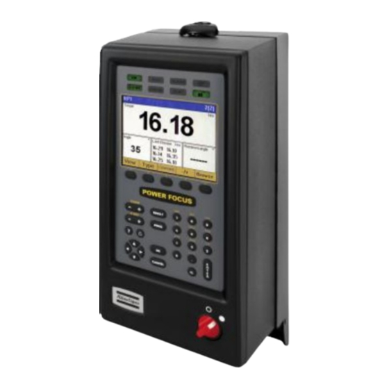
PF user interface 5.1.2 Display PF 4000 Graph features a large back-lit 72 x 96 mm color display with a dialog box-like interface to allow accurate measurement readings and simple programming. r with three fields: channel number and Heade current Pset or Job, Pset name, and number of tightenings (in batch). -
Page 44: Programming Pf Graph
PF user interface Data input To access the data input boxes, do one of the following: Highlight it and then press ENTER Press the digit on the numeric keypad that corresponds to the option. To enter data, do the following: ... - Page 45 PF user interface If another person or program has programming control, a message is displayed. When a change has been made, is shown in a lighter color. Press the soft key below to confirm Store Store changes. Press to return to the result view. RESULT Programming another PF To program another PF through PF Graph, both channels have to be members of the same cell.
- Page 46 PF user interface Press and then to open the result PROG 4,5,1 view. Press to select one or two channels. The programming mode for the result view is displayed. Press the number in the area to edit, then press to open the selection list for the result Enter view area.
- Page 47 PF user interface Print reports The print key opens the print menu. If print is selected from, for example the controller menu, the controller report is pre-selected. Trace One or multiple traces can be shown in the PF Graph display. To show traces select in the Trace...
- Page 48 PF user interface trace mode it is Torque over time possible to plot several traces in the same chart. This is done by accessing the Select menu block and activating Multiple Traces The last ten traces are displayed in the chart.
-
Page 49: Pf Compact
PF user interface PF Compact can be programmed in ToolsTalk PF, through a pre-programmed RBU, or programmed using PF Compact the cell function on a PF Graph. A Pset can also be programmed directly via the unit’s Auto set function. Except for differences in the user interface, PF Compact has the same functionality and capacity as the Graph model. -
Page 50: Display
PF user interface 5.2.2 Display After a tightening, result is presented on the display in configured presentation unit. If the presentation value is bigger than 9999, display shows ‘EEEE’. Engineering unit Convert factor Nm to Ozfin 141.6 Nm to Lbfin 8.851 Nm to Lbfft 0.737562... -
Page 51: Indicator Lights
PF user interface 5.2.3 Indicator lights Indicator Description The OK light indicates when the result of the tightening is within the specified limits. The indicator remains active until the next cycle starts. OK flash light indicates that it is safe to disconnect the tool. The LED goes off when the tool is disconnected. -
Page 52: Keypad
PF user interface 5.2.4 Keypad Description Plus [+] Navigates through menus on the display and increases numbers. Minus [-] Navigates through menus on the display and decreases numbers. Autoset Press the Autoset key to enter Autoset programming mode. (arrow target) Aset/Ft alternates in the display and the Autoset LED comes on. - Page 53 PF user interface Function Description Key [F] Press the key three times. F3/tool alternates in the display if a tool is connected. Otherwise F3/---- is displayed. Motor tuning Press Enter to activate the motor tuning process. The display shows the process status during progress, (1 to 7). Press the to start motor tuning.
-
Page 55: Getting Started With Toolstalk Pf
It is possible to select installation of multiple instances of ToolsTalk PF. This means it is possible to open several ToolsTalk PF instances at the same time in your desktop. Open ToolsTalk by selecting Start > Program > Atlas Copco Tools AB > ToolsTalk Power Focus 9836 3123 01 55 (428) -
Page 56: Toolstalk Overview
Getting started with ToolsTalk PF ToolsTalk overview Almost every function in ToolsTalk PF has its own window. The figure below shows the ToolsTalk PF interface with menu list, selection panel, toolbar and PF Map. There are several ways to start a function in ToolsTalk PF. With almost all functions, it is possible to use a menu item in the menu list. - Page 57 Getting started with ToolsTalk PF Illustration Name Description File Read and store files, print and exit ToolsTalk PF from the File menu. If, for example, the Pset window is active, options for reading and storing Pset appear in the File menu. Edit Create a new Pset, Multistage, Job, Sound and Logic Configurator from the Edit menu.
- Page 58 Getting started with ToolsTalk PF Illustration Name Description Options The Options menu includes: ToolsTalk interface settings: View Toolbar, Settings, Change language and Change Manual. See section Configuring ToolsTalk for more information. Get Event Log: Retrieves the event log from the connected PF Forced release progcontrol terminates the connection to the current PF and enables another user to take programming control over...
-
Page 59: Selection Panel
Getting started with ToolsTalk PF Illustration Name Description Activate The Activate menu contains a list of all available functions (Pset, Job, Multistage, etc.). Help The Help menu allows access to the Power Focus help file. Pressing F1 on the keyboard gives access to the help file from any window. -
Page 60: Toolbar
Getting started with ToolsTalk PF Running If parameter C200 Pset is set to Ethernet/Serial, it is Pset/Multistage possible to select a Pset or Multistage to run. PF List To simplify the Ethernet connection to a Power Focus, use the PF List. Select an item and ToolsTalk PF connects to the corresponding Power Focus. - Page 61 Getting started with ToolsTalk PF Icon Icon name Description Tool This icon opens the first part in the Tool programming section. The Tool branch includes information, configuration, diagnostic and maintenance for the Tensor tool connected to PF. Use the arrow to the right to select between the sub-menus. Accessories This icon opens the first part in the Accessories programming section.
-
Page 62: Pf Map
Getting started with ToolsTalk PF Icon Icon name Description Connect The Connect icon changes appearance depending on the connection status. When the PC is not in contact with the Power Focus, this icon is visible. Clicking on it establishes a connection between the PC and PF. -
Page 63: Configuring Toolstalk Settings
Getting started with ToolsTalk PF Configuring ToolsTalk settings This section describes some of the available ToolsTalk settings. The following settings are located in the dialog box. The settings are configurable off-line. Settings Setup for communication with PF Setup for viewing information inside the ToolsTalk PF application ... - Page 64 Getting started with ToolsTalk PF In the area, select which Com port to use on the PC, normally Com1 or Com2, for Serial setup communication with PF. The Baud rate can be set to 2400, 4800, 9600, 19200, 38400, 57600 or 155200. The TTPF baud rate must match the baud rate set in PF.
-
Page 65: Application
Getting started with ToolsTalk PF 6.3.2 Application tab has three areas; , and Application Presentation, Automatic functionality Default directory The first area concerns the ToolsTalk PF presentation. If the checkbox is selected, then the limits for each parameter are displayed in the status bar Show hints when the cursor is placed over a parameter box. -
Page 66: Printout
Getting started with ToolsTalk PF area activates/deactivates the following functions: Automatic functionality Auto collapse tree views Type of connection at startup: If Serial auto connection on startup Ethernet auto connection on is checked, ToolsTalk PF connects to Power Focus immediately on start-up. startup ... -
Page 67: Pf List
Getting started with ToolsTalk PF 6.3.4 PF List tab contains the box. Add, modify and remove items from here. PF List PF available list PF Ethernet defines PF in the net, seen from ToolsTalk. Note that the configuration of PF in the net is made from type PF Map>Controller>Network 9836 3123 01... -
Page 68: Connecting A Pf
Getting started with ToolsTalk PF Connecting a PF There are different types of connection possibilities; Ethernet TCP/IP, Serial RS232 and USB. USB connection is only available for PF 4000. 6.4.1 Ethernet connection To make an Ethernet connection between PF and Tools Talk, PF must be configured with a unique IP address. -
Page 69: Usb Connection
If using a different OS then above or to get the latest version of drivers, this driver can be download from: http://www.ftdichip.com/Drivers/VCP.htm Also a detailed installation guides are available from: http://www.ftdichip.com/Documents/InstallGuides.htm Contact Atlas Copco representative to obtain more information about available drivers. 9836 3123 01 69 (428) -
Page 70: To Connect
Getting started with ToolsTalk PF 6.4.4 To connect There are several ways to connect a Power Focus from ToolsTalk PF: Select in the Menu list and then choose between Focus Serial connection Ethernet connection In the drop-down list for controller in Selection panel, click on either Selected Serial PF... -
Page 71: Store Pf To File
Getting started with ToolsTalk PF See table below for option descriptions. Option Description Store PF to File Programmed settings in the Power Focus are stored to a file when connected to a Power Focus. Read PF from File Power Focus updates with programmed settings stored on file when connected to a Power Focus and performing Read PF from file. -
Page 72: Read Pf From File
Getting started with ToolsTalk PF 6.5.2 Read PF from file Command “Read PF from file” overwrites current programming and configuration in connected PF. It is necessary to perform “Read PF from file” TWO times and reboot PF one extra time for changes to take effect. -
Page 73: Offline
Getting started with ToolsTalk PF Offline mode gives the user the opportunity to conduct programming and configuration, without a PF Offline connection. All programming is stored to or read from a file. It is possible to copy this file to one or more PF units. -
Page 74: Configuring A Tool Offline
Getting started with ToolsTalk PF 6.6.1 Configuring a tool offline In offline mode, open in the Tool>Information PF Map Click . The window appears. Set tool Set tool Select a tool or configure a new tool via the Create tool key 74 (428) 9836 3123 01... -
Page 75: Pset
This section includes screenshots from ToolsTalk PF. The screenshots show examples of parameter settings and are NOT intended to be generally applicable. Check with your local Atlas Copco representative how to set up your specific system environment. See parameter list section Pset for a description of all available Pset options. -
Page 76: Create New Pset/Open Pset
Pset All Pset changes are reflected in ToolsNet. Create new Pset/Open Pset In the right-click and select PF Map, Create New Pset Alternatively, or right click double-click on an existing Pset, to open the Pset configuration window. As default there is one Pset existing in ToolsTalk PF. -
Page 77: Autoset
Pset Autoset An easy way to program a Pset is to use the function. Power Autoset Focus adapts the programming to the specific joint characteristics and sets all the parameters automatically. Autoset does not change any parameters outside the used Pset. Autoset uses DS con for DS tools and P100 Control strategy... -
Page 78: Quick Programming
Pset Perform a number of tightenings with the tool. The first two tightenings are completed at very low speed. Normally, three to ten tightenings are required in order for the Power Focus to calculate and set the required parameters for the specific joint characteristics. -
Page 79: Programming Help
Pset Open an existing Pset or create a new one. Click in the Pset Quick programming window. Select and enter P100 Control strategy the joint angle and P113 Final target Click to finish. Programming help Via the function ToolsTalk PF can illustrate an Programming help example of the selected control and tightening strategy. -
Page 80: Programming
Pset Programming In the Pset setup window, expand the branch. Programming Select Control Choose the desired P100 Control strategy P101 Tightening strategy settings for the other parameters. For more information, see sections Control strategies, Tightening strategies and Additional control options. 80 (428) 9836 3123 01... - Page 81 Pset In the Pset branch, Programming select Torque Angle Make suitable parameter settings. 9836 3123 01 81 (428)
- Page 82 Pset In the Pset branch, Programming select Speed and ramp Time Make suitable parameter settings. 82 (428) 9836 3123 01...
- Page 83 Pset In the Pset branch, Programming select Batch count, High speed rundown, Positioning Snug gradient Make suitable parameter settings. Click to save the settings. Store 9836 3123 01 83 (428)
-
Page 84: Control Strategies
Pset Control strategies For all tightenings the process starts when the torque reaches . When the Tq con DS con P110 Cycle start torque reaches target and then falls below the process ends. When the torque drops P115 Cycle complete below without having reached target before, a timer is started. -
Page 85: Tq Con/Ang Mon
Pset 7.6.2 Tq con/ang mon Torque strategy Tq con/ang mon controls the torque and monitors the angle. This strategy is selectable for both one and two stage tightenings. The tool stops when the torque reaches the P113 value. Final target If the tool for some reason should exceed P114 Final tq max... -
Page 86: Tq Con/Ang Con (And) / (Or)
Pset 7.6.4 Tq con/ang con (AND) / (OR) Torque Tq con/ang con (AND)/ (OR) strategy controls both torque and angle. This strategy is selectable for both one and two stage tightenings. , Power Tq con/ang con (AND) Focus controls the P113 Final target value and the P123 Target angle... -
Page 87: Reverse Ang
Pset 7.6.5 Reverse ang strategy reverses Reverse ang Torque the spindle a specified number of degrees in the opposite tool tightening direction. This is useful when, for example, the bolt needs to be loosened before the final tightening. Create a Multistage to combine and perform several Psets as one. -
Page 88: Rotate Spindle Forward/Reverse
Pset 7.6.6 Rotate spindle forward/reverse Torque rotate spindle forward/reverse functions rotate the spindle a specified number of degrees, either forward or reverse, independently of torque. The only torque values monitored are P114 Final tq max P112 Final tq min is defined as the P123 Target angle number of degrees between start of tightening and the peak angle. -
Page 89: Home Position Forward And Reverse
Pset Resulting torque is the final target set by the Pset. 7.6.8 Home position forward and reverse Torque function, home position suitable for fixtured tools, makes it possible to mark a socket position using the Set home digital input. When position triggered, the socket rotates (CW or CCW... -
Page 90: Yield Control (Yield)
Pset 7.6.9 Yield control (Yield) Yield control is activated by selecting the . The can be P100 Control strategy Yield P101 Tightening strategy set to . Yield control interacts in the second stage of the tightening. One stage Two stage Quickstep P105 strategy ending is eliminated when yield control is selected. -
Page 91: Ds Con
Pset 7.6.11 DS con Torque function controls the DS con torque based on the current measurement and monitors the angle. This function is selectable for two stage tightenings only. The tool stops when the torque reaches the value. P113 Final target If the tool for some reason should exceed , the... -
Page 92: Ds Con/Tq Mon
Pset Calculate the mean value from the tightenings Final Target Torque Tuning Factor Torque Tuning Factor Measured Mean Enter and store the new DS torque tuning factor Perform another set of tightenings to control the torque ... -
Page 93: Snug Gradient
Pset 7.6.13 Snug gradient strategy runs Snug gradient the specified P123 Target angle from the observed Snug point. controls the angle Snug gradient and monitors the torque. This strategy is selectable for both one and two stage tightening. The Snug gradient is the slope Snug point calculated by P180 Delta angle... -
Page 94: Pvt Comp With Snug
Pset 7.6.14 PVT comp with snug This tightening strategy is a development of the existing strategy described in PVT comp 7.8.4. This strategy is useful when the PVT Snug point comp torque level is higher than P113 Final P185 compensate value Peak target Average... -
Page 95: Tightening Strategies
Pset Tightening strategies The Power Focus supports a number of different in order to achieve the best quality, tightening strategies speed and ergonomic behavior. Both standard and proprietary patented strategies are supported. This section provides a generic description of the tightening strategies available. 9836 3123 01 95 (428) -
Page 96: One Stage
Pset 7.7.1 One stage Tightening is performed in Torque until the stage P113 Final target torque has been reached. Time 1. P110 Cycle start 2. P113 Final target 3. P130 Soft start speed 4. P135 Step 1 ramp 5. P131 Step 1 speed Tool 6. -
Page 97: Quick Step
Pset 7.7.3 Quick step is a type of two stages Quick step Torque tightening with high tool speed during the first stage and a lower tool speed during the second stage. The speed changes from first to second stage speed without pausing in between. -
Page 98: Ergo Ramp
Pset 7.7.4 Ergo ramp is a two stage Ergo ramp Torque tightening with a constant increase of torque during the second stage. It is set automatically using the programmed value P137 Ergo ramp and the hardness of the joint. Time This strategy has the ergonomic advantage of giving the user the same reaction torque in the second... -
Page 99: Rehit Detection
Pset 7.7.6 Rehit detection The rehit functionality is designed to detect re-tightenings of an already tightened joint, thereby avoiding batch counting errors etc. Two parameters have been found to be good indicators of a so-called rehit, tool speed and tightening angle. If, for two stage torque control tightenings, the tool does not get up to speed before the first target occurs and the angle of the second stage is not great enough the rehit alarm is activated. -
Page 100: Current Monitoring
Pset , for monitoring joint hardness. Gradient monitoring , available for PF 4000, for individual joint control at the Yield control second stage of the tightening. function makes it possible to monitor torque Post view torque values during two specified angular intervals. 7.8.1 Current monitoring Select... -
Page 101: Pvt Selftap
Pset The spindle torque is Torque proportional to the motor current. By measuring motor current, a method of measurement that is independent of the torque transducer is achieved. The torque forming current is expressed as a percentage of the nominal current at T102 Tool max torque With... -
Page 102: Pvt Monitoring
Pset impact on the calculated mean value and vice versa. A high number of windows make the monitoring more sensitive; a low number filters more noise. Torque 1. P211 Selftap interval 2. P110 Cycle start 3. P213 Selftap min 4. P214 Selftap max 5. - Page 103 Pset With selected, an acceptance window for the torque before P220 PVT monitoring P116 Rundown complete set. The is monitored in real time during the . The tool stops P225 PVT max limit P222 PVT monitor interval immediately if this limit is exceeded. The is evaluated against the monitor interval P224 PVT min limit average value at the end of the interval.
-
Page 104: Pvt Compensate
Pset 7.8.4 PVT compensate In the Pset branch, Programming + select PVT compensate Via the function, PF allows the PVT compensate P111 First target, P113 Final target P114 Final tq max be compensated for the prevailing torque during the rundown phase. The PVT compensation value is calculated at as an average torque from an P116 Rundown complete... -
Page 105: Options
Pset 7.8.5 Options In the Pset Programming + branch, select Options Make suitable parameter settings. See parameter list section Pset for information on parameters P241-P247. P240 see below. Tool rotation direction There are different variables that control the tool rotation direction: tool direction ring, P240 Tool tightening direction P101 Tightening strategy... -
Page 106: Gradient Monitoring
Pset remote start input is used the tool trigger is disabled. If a digital input is used as start signal input, the direction ring and trigger on the tool are bypassed and the tool starts tightening in the direction programmed in the parameter P240 Tool tightening direction The fieldbus tool start input works in the same way as the tool start from digital input. -
Page 107: Yield Control
Pset Torque When this function is activated, a gradient is calculated for each new torque and angle sample available. Tightening is aborted and a gradient high or low result is displayed if the gradient exceeds the limits. Angle 1. P254 Start torque 3. - Page 108 For the STwrench tool interfacing with the PF, the yield strategy is programmed in a different way. Only parameter P264 Extra angle step needs to be set together with the torque target and limits, and the angle limits. Check with your local Atlas Copco representative how to setup your specific application.
-
Page 109: Post View Torque
Pset Torque Angle 5. P264 Extra angle step 1. P260 Start Torque 6. P262 Yield slope ratio, example 100% 2. P261 Step angle 7. P262 Yield slope ratio, example 70% 3. P262 Window angle 4. Torque difference (TDIFF) 7.8.8 Post view torque In the Pset branch, Programming +... -
Page 110: Pset Setup
Pset Some joints have a torque Torque peak prior of P116 Rundown . Post view torque complete function makes it possible to monitor torque values during two specified angular intervals. The interval start is defined as angle prior to P116 Rundown . - Page 111 Pset Add a name for the Pset (optional). This section also contains options for View existing Pset Create new Pset Copy Pset Delete Pset Click Delete Pset result select the Pset result to remove from the Power Focus memory. When clicking Delete all results a confirmation window appears.
-
Page 112: Statistic Programming
Pset 7.10 Statistic programming Expand the branch. Statistic programming In this branch it is possible to define conditions to be included in the statistical calculations for the tightenings (Psets). Click to save the settings. Store 7.11 Running a Pset To run (activate) the Pset, select the Pset in the or via any configured Pset control source. -
Page 113: Multistage
This section includes screenshots from ToolsTalk PF. The screenshots show examples of parameter settings and are NOT intended to be generally applicable. Check with your local Atlas Copco representative how to set up your specific system environment. See parameter list section Multistage for a description of all available Multistage options. -
Page 114: Create New Multistage/Open Multistage
Multistage Create new Multistage/Open Multistage In the PF Map, mark Multistage and select right-click Create New . Alternatively, Multistage double- on an existing Multistage to click open the configuration window. Select , enter New Multistage ID New Multistage name (optional) and click to open the Multistage window. - Page 115 Multistage The Multistage strategy is not supported by Power Focus with wireless tools. 9836 3123 01 115 (428)
-
Page 117: Job
This section includes screenshots from ToolsTalk PF. The screenshots show examples of parameter settings and are NOT intended to be generally applicable. Check with your local Atlas Copco representative how to set up your specific system environment. See parameter list section Job for a description of all available Job options. - Page 118 Controller Job example The figure to the right shows an example of an object with bolts that require different torque values: Four bolts that require a torque of: 39 Nm Three bolts that require a torque of: 70 Nm One bolt that requires a torque of: 88 Nm For this example three different Psets have to be created: ...
-
Page 119: Job Configuration
Controller Job configuration 9.2.1 Creating a Job group The PF units in a Job group must be working in the same Cell. Therefore, before creating Job groups a Cell has to be configured (see section Controller for more information). After cell configuration, the next step is to create a Job group including Job reference and Job client. In the , select PF Map... -
Page 120: Creating A New Job
Controller 9.2.2 Creating a new Job With the configuration setup it is possible to store up to 400 Jobs (see section Memory for more information). When creating a Cell Job the programming has to be done in the Job reference controller. Right-click in the PF Map and select... - Page 121 Controller Auto select is not allowed for free order Jobs, with two or more Psets/Multistages selected from the same Power Focus. The batch size defined in Job overrides the batch size defined for a specific Pset/Multistage (see parameters . It is not recommended to use the P150 Batch count M202 Batch count batch count function in Job and Pset/Multistage settings simultaneously.
-
Page 122: Select Job
Controller 9.2.3 Select Job Power Focus allows two different possibilities for Job selection; . To be C201 Job C202 Job override able to select a Job at least one of the two parameters has to be set. The parameters are set from . - Page 123 Controller Two cases when the Job reference loses the communication with a Job client during a running Job: If the disconnected Job client has tightenings left to perform, the Job reference will abort the running Job immediately. If the disconnected Job client did not have any tightenings left to perform, or had no part in the running Job, the Job continues.
-
Page 124: Functions In The Job Monitor
Controller In ToolsTalk PF, click on the arrow to the right of the Monitor icon select Job Monitor Job monitor displays the selected Job and provides a management function. For description of Job off Restart Job Decrement Increment Bypass , see section Functions in the Job monitor. Abort Job Functions in the Job monitor Function... -
Page 125: Unlock The Tool
Controller Function Description Bypass Bypass skips a specific Pset/Multistage in a running Job, independently of batch size. The batch counter will be set equal to the batch size value and the Pset will be considered as completed when a Pset/Multistage is bypassed. The Job status will be OK/NOK depending on the parameter J311 Batch status at Increment/bypass In a Job with free order, only the Job client with the active Pset/Multistage is able to use the bypass function. -
Page 126: Controller
This section includes screenshots from ToolsTalk PF. The screenshots show examples of parameter settings and are NOT intended to be generally applicable. Check with your local Atlas Copco representative how to set up your specific system environment. See parameter list section Controller for a description of all available Controller options. - Page 127 Controller This window contains information about the ToolsTalk PF Software the Power Focus Hardware 9836 3123 01 127 (428)
-
Page 128: Configuration
Controller 10.2 Configuration In the PF Map branch, double-click on Controller Configuration Make settings for Select source Selector: A selector configured on the I/O bus. Digin: A digital input can be a device on the I/O bus, an internal digital input, an ST GPIO device or a Logic configurator. - Page 129 Controller Make settings for Tightening Loosening Positioning The parameter C230 OE positioning type defines how the open-end position is reached. In all C230 strategies the tools rotates slowly the first 30° to detect that the tool is not in contact with the nut.
-
Page 130: Network
Controller Make settings for Batch Startup Click under Date and Time store computer and user time to Note! If using Toolsnet, Toolsnet will act as the Date and Time master synchronizing the time in the PF to the time in Toolsnet. Click to configure which Events... - Page 131 Controller In the PF Map branch, double-click on Controller Network Make settings for Ethernet Cell 9836 3123 01 131 (428)
-
Page 132: Cell And Net Configuration
Controller If used, activate and setup Multicast Make settings for Open Protocol, Tools and the port. Talk Acta If used, activate and setup ToolsNet Click to save settings. Store 10.3.1 Cell and Net configuration The Power Focus software offers extended networking possibilities. The concepts are part Cell of the RBU Gold and RBU Silver types. - Page 133 Controller A cell consists of one a maximum of 19 thus a total of 20 PF units. Cells Cell reference, Cell members, can then be grouped into ; the maximum number of cells in a net is 1000. Each net has a Nets .
- Page 134 NOT intended to be generally applicable. Check with your local Atlas Copco representative how to set up your specific system environment. To set up a network, PF must have an IP-address. See section Connecting a PF.
- Page 135 Controller Open PF Map>Controller>Network Set the C300 IP address C301 Subnet mask C302 Default router Set the to the IP address of the C312 Cell reference IP Cell reference. Set the to the IP address of the C315 Net reference IP Net reference.
-
Page 136: Com Ports
Controller If the C315 Net reference IP address has not been entered in a PF when adding it to the network, the added PF will be shown as a controller in the PF Map list of the Netmaster anyhow. 10.4 COM ports In the PF Map branch, double-click on... -
Page 137: Display
Controller 10.5 Display In the PF Map branch, double-click on Controller Display to make settings for the controller display. 9836 3123 01 137 (428) -
Page 138: Memory
Controller Make settings for Presentation Result view Keyboard Power save Note that there are more selections available on the controller display. See parameter list section Display. Click to save settings. Store Make settings for screen colors: Color theme Background color for result color for OK result Foreground (text) - Page 139 Controller Besides the 'default configuration' and 'totally configurable' (which gives the possibility to manually configure the Power Focus memory freely), Power Focus provides seven more configurable memory options; More Psets, More Jobs, More Results, More Events, More Identifiers, QDAS, Pset comments. Selection Psets Jobs...
- Page 140 Controller In the , select PF Map Controller>Memory Make a selection for . To manually configure the C600 Type memory, select Totally configurable Click to continue. Select number of Psets, Jobs, Results, Identifier result parts, Events, Statistical events and Traces. Indicator estimated memory usage is automatically updated in percent (a maximum of 100...
-
Page 141: Accessibility
Controller Memory reset Store important data, see Store PF to file, including Psets, Multistages, and Jobs before resetting the memory. The data can later be retrieved, see Read PF from file. In the , select PF Map Controller>Memory To reset the memory or parts thereof, click the corresponding button. - Page 142 Controller Make settings for Password Passwords should have between 1 and 8 characters (letters or numbers) and are case sensitive. There are separate passwords for communication and setup parameters. An identical password can be set for both. In this case only one password will be prompted in TTPF, but still both in PF graph.
-
Page 143: Tool
NOT intended to be generally applicable. Check with your local Atlas Copco representative how to set up your specific system environment. See parameter list section Tool for a description of all available Tool options. See tool specific information for more information about the options for each tool. - Page 144 Tool sections contain Model Motor information about the Tensor tool connected to PF. section contains information Software about the application- and boot-code version for the tool. 144 (428) 9836 3123 01...
-
Page 145: Tool Configuration
Tool 11.2 Tool configuration In the PF Map branch, double-click on Tool Configuration The following submenus are available: 11.2.1 Tool start and Accessory bus Make settings for Tool start Accessory The main purpose of T200 Tool start select option “Safety source trigger”... - Page 146 Tool while the tool is running, the tool stops immediately. Once the tool has been started, the safety trigger function requires both buttons to be released before the tool can be started again. A safety trigger button is mounted on the ST tool and connected to GPIO 4. The parameter is only accessible when GPIO 4 is set to “Off”.
-
Page 147: Sound And Buzzer
Tool 11.2.2 Sound and buzzer In the window, the settings include the type of sound and the event that should trigger the sound. Sound Make settings for Sound Enable/disable sound and adjust the volume. Two types of sound files can be stored in the Power Focus memory, buzzer and sound (stream) waves. A is a frequency-based sound generated by the tool. - Page 148 Tool window appears. BuzzerWave Give the Buzzer wave an E100 Name (recommended). Select E101 Frequency E102 Time On E103 Time E104 Repetition E105 Volume The volume is a relative (in percent) of parameter , which could be set to high, medium T221 Volume or low.
-
Page 149: Tool Function Buttons
Tool To connect a configured buzzer or sound to an event, click in the Sound window. Select a digital output (relay) in the Event list. Select a sound or buzzer wave (created earlier) in the list to connect to the event. Sound Type Select a priority from the list connected to the specific sound event. - Page 150 Tool Single push Timeout Button pressed Button released Time Push detection interval Next push interval - the button is pressed down and released before the expires. The Single push T236 Push detection interval expires before the button is pressed again. T237 Next push interval Double push Button pressed...
-
Page 151: Blue Led
Tool From the digital input functions point of view, single push and double push user interaction types do generate pulses. This means that they do not have duration where input to the digital input function remains high. user interaction types are therefore not suitable for digital Single push Double push input functions that are intended to “follow”... -
Page 152: Tool Illuminator And Lights
Tool 11.2.5 Tool illuminator and lights Make settings for Illuminator Lights The illuminator, which is a group of LEDs in the front of SL and ST pistol tools, provides light for the operator during tool operations. The parameter can be set to: T250 Illuminator mode ... -
Page 153: Radio And Connection
Tool 11.2.6 Radio and Connection Make settings for Radio Connection. Some of the settings are explained in detail below. All of the tool configuration parameters are listed in tool parameter section Configuration. The radio section is accessible when Primary tool is other than Cable. IRC turns off after this time, if tool is inactive. -
Page 154: Tool Diagnostic
Tool 11.3 Tool diagnostic In the PF Map branch, double-click on Tool Diagnostic Click to introduce torque Sensor tracking and angle readings in real time. Click to diagnose tool LED's Peripherals and buttons. Temperature parameters are for information only. Click under Active response time Radio... -
Page 155: Sensor Tracking
Tool 11.3.1 Sensor tracking To monitor Torque/Angle readings from the tool press . To set reference point for Angle Start value during monitoring press Reset For S, DS tools it is even possible to read value of the transducer offset shown in percentage of the nominal torque range. - Page 156 Tool * There are different definitions of gain (shunt calibration) parameter for each tool depending on HW/SW solution implemented. STB uses no shunt calibration. 156 (428) 9836 3123 01...
-
Page 157: Tool Maintenance
Tool 11.4 Tool maintenance In the PF Map branch, double-click on Tool Maintenance The following submenus are available: 9836 3123 01 157 (428) -
Page 158: Calibration And Service
Tool 11.4.1 Calibration and Service Make settings for Calibrations Service Click to save the Store settings. 11.4.2 Open-end tuning Before using an open-end tool, make sure that the tool head and tool body have been assembled and configured correctly. If not, the tool can run in the wrong direction and the mechanical stop in the open- end head may be damaged. - Page 159 Tool For S, ST and DS tools, use parameter T420 Use open end activate the open-end functionality. For SL and STB tools it is not possible to change the open-end parameters in Tools Talk or Graph. Use Tools Talk Service to modify open-end settings.
-
Page 160: Wear Indicator
Tool 11.4.3 Wear indicator Wear indicator provides a mechanism to inform tool users with an event code when it is time for tool service. It is also possible to configure a controller to lock the tool with parameter T416 Lock tool on alarm The amount of wear before an alarm is issued is set in T433 Alarm factor... -
Page 161: Motor Tuning
Tool Click to create the Psets and Create QRTT Multistages needed. The target torque and angle is then set by the ACTA 4000 before the start of each calibration. The tool calibration is started by a command from the ACTA 4000 or by pressing the tool trigger depending on if the tool is configured for remote start or not. -
Page 162: Disconnect Tool
Tool Standalone motor tuning Click Perform motor tuning Press and keep it pushed Tool trigger during the motor tuning process (the status is displayed). Release or click Tool trigger Abort cancel. When finished the result of the motor tuning is displayed. Sync motor tuning Click Sync motor tuning... - Page 163 Tool Do not disconnect a tool during tightening, loosening, positioning, motor tuning, open-end tuning or tracking. Logical disconnection is not necessary for ST and SL tools (this tool types allows hot swap functionality). If the operation succeeded, the green OK LED flashes continuously (on the Power Focus) and the message “Command accepted”...
-
Page 164: Hot Swap
Tool 11.4.7 Hot swap It is possible to replace an individual tool with another tool, just by disconnecting the tool from the tool cable and attach the new tool. Hot swap is only available for S and ST type tools. When hot swapping a tool, the new tool must be of the same type to ensure that all parameter settings in the Power Focus will be interpreted correctly. -
Page 165: Intentional Locking Of Tools
Tool For enabling the tool, use the external source for selecting the Pset in Power Focus when the conditions for “start tightening” are fulfilled For disabling the tool, use functions , which are internal P152 Lock at batch ok J302 Lock at Job done tool locking sources within Power Focus 11.5.2... -
Page 167: Accessories
This section includes screenshots from ToolsTalk PF. The screenshots show examples of parameter settings and are NOT intended to be generally applicable. Check with your local Atlas Copco representative how to set up your specific system environment. See parameter list section Accessories for a description of all available Accessories options. - Page 168 Accessories dialog box appears. I/O set Select Device type Select (with relay timer). For more information, see section Digital I/O and Digital inputs Relays fieldbus items. Note that must be set to Yes before the digital inputs and relay settings for line J330 Use line control control can be activated.
- Page 169 Accessories In the , open and double-click PF Map Accessories>Digital I/O or right-click and select Diagnostic, Diagnostic Open I/O Diagnostic window appears. I/O Diagnostic Here the status of all internal and external I/O devices can be viewed. It is possible to set the status of relays. All configured I/O devices appear on the list of available devices. This function enables testing of the interaction between PF and different external devices.
-
Page 170: I/O Bus
Accessories 12.2 I/O bus Power Focus has extensive I/O capabilities. Apart from the internal I/O ports it is also possible to connect up to 15 external I/O devices to the Power Focus I/O bus. In the PF Map, open and double-click Accessories>I/O bus Information 170 (428) - Page 171 Accessories Information for each device on the I/O bus is displayed. Click to configure the selected device. Config Click to diagnose the selected device. Diagnostic In the PF Map, open Right- Accessories>I/O bus. click and select Configuration Create new I/O Device Alternatively, on an existing I/O double-click...
- Page 172 Accessories Select New I/O Device ID Device type Click to open the configuration window. Make settings for the device by clicking on the positions (the example below shows an Operator panel). See the user guides for each accessory device for more information. Click when finished with configuration.
- Page 173 Accessories 9836 3123 01 173 (428)
- Page 174 Accessories In the , open and double- PF Map Accessories>I/O bus click Options Make settings for Options Click window when finished. Store Close 174 (428) 9836 3123 01...
-
Page 175: Tool Bus
Accessories 12.3 Tool bus In the , open and double-click PF Map Accessories>Tool bus Information Select Device type and click Device information The Device information window appears with information about the connected device. 9836 3123 01 175 (428) - Page 176 Accessories In the , open and double-click PF Map Accessories>Tool bus Configuration In the Tool bus Configuration window, click General purpose I/O Make settings for the digital inputs and outputs (see section Digital I/O and fieldbus items for descriptions of available selections).
- Page 177 Click Set Scan Engine Default to delete all custom scan Values engine settings and revert back to the Atlas Copco production defaults. Click Set Highest Security Level to set the scan engine Linear code type security setting to its highest level (4) and turn the Bidirectional redundancy on.
-
Page 178: Printer
Accessories In the Tool bus Configuration window, click TLS ST Tag Make settings for the ST Tag. 12.4 Printer In the , open > PF Map Accessories Printer 178 (428) 9836 3123 01... - Page 179 Accessories The connected A400 Brand A401 are setup here. If Paper size A402 is activated, then it is Continuous print possible to also select A404 New page at Job done Push the Print button on the Power Focus Graph front panel to view a list of available reports to print.
-
Page 181: Sync
This section includes screenshots from ToolsTalk PF. The screenshots show examples of parameter settings and are NOT intended to be generally applicable. Check with your local Atlas Copco representative how to set up your specific system environment. See parameter list section Sync for a description of all available Sync options. -
Page 182: Sync Prerequisites And Limitations
Sync Synchronization during the final tightening. 13.1 Sync prerequisites and limitations A Sync group consists of two to ten PF units. The SynchroTork option is limited to six tools. All Sync members must be part of the same cell, but a cell can consist of more than one Sync group. The cell reference does not have to be a member of the Sync group. -
Page 183: Hardware Configuration
Sync 13.2 Hardware configuration Connect all PF units in the Sync group via the I/O-bus on the back panel. Set the 4-pin remote start connector to remote start on each of the Sync members, and to the selected start source on the Sync reference. If applicable, connect external I/O devices (for example alarms or start source) to the Sync reference, but never to the Sync members. -
Page 184: Sync Configuration
Sync 13.3 Sync configuration To set up a Sync group, configurations are made in Network windows. Tool Sync 13.3.1 Sync members configuration Connect the Sync reference. In the PF Map, open > Controller Network 184 (428) 9836 3123 01... -
Page 185: Sync Reference Configuration
Sync Ensure that all PF units in the Synchronized group are part of the same Cell. Parameter C312 must be the same. Cell reference IP In this example, PF is a Sync member, and the Sync reference is the same as the cell reference. Click to save settings. - Page 186 Sync 186 (428) 9836 3123 01...
-
Page 187: Troubleshooting
Sync 13.4 Troubleshooting Follow the procedure in this section. For more information, see section Event codes. Symptom Reason/Action Tools in a Sync group do not Programming errors: start or do not tighten Check that all Psets are configured from the Sync reference. correctly Check that all Sync members have set to Sync start. -
Page 189: Identifier
This section includes screenshots from ToolsTalk PF. The screenshots show examples of parameter settings and are NOT intended to be generally applicable. Check with your local Atlas Copco representative how to set up your specific system environment. See parameter list section Identifier for a description of all available Identifier options. -
Page 190: Identifier Prerequisites And Details
Identifier is additional information stored together with each tightening result in the Power Focus Result part database. This information can come from one or more of the defined identifier types independently. Multiple identifiers provide storage of up to four result parts (RBU-dependent) after memory reconfiguration. - Page 191 Identifier The number of characters in the significant string (for example 10) must be the same as the number of significant positions The length can be max 100 characters Standard alphanumeric characters are accepted. Apostrophe (’) and colon (:) are not accepted ...
-
Page 192: Configuration Of Identifier Functions
Identifier The parameters J342 Reset all identifier at Job done I183 Reset all identifiers at Pset batch done activated After a reset, the following occur: All identifiers are reset Work order is (cleared) aborted Tool is unlocked if is activated I181 Tool locked during work order 14.3... -
Page 193: Configuring Identifiers
Identifier 14.3.1 Configuring identifiers The procedure to set identifiers differs between identifier types 1 and types 2-4. Always start with Type 1. To set up identifiers, do the following: In the PF Map, double-click to open the window. The figure below shows a Identifier Type setup completely configured identifier setup. - Page 194 Identifier Note: To define the significant string for identifier Type 2-4, click the box and type the string directly. Write string name in field and click Add identifier string Wildcards can be used in Type 1 strings if the significant positions are different and outside the length of some Type 1 strings.
-
Page 195: Configuring A Work Order
Identifier 14.3.2 Configuring a work order To configure a work order, do the following: Open PF Map > Identifier > Options Add identifier types to the work order, and arrange the correct order using the arrow buttons. Note: Identifier Type 1 must always be included in the work order. If applicable, select Tool locked during work order I183 Reset all identifiers at Pset batch done... -
Page 196: Configuring Result Parts
Identifier 14.3.3 Configuring result parts To configure more than one result part, the parameter must be set to the C604 No of Identifier result parts correct number of result parts. If a memory reconfiguration is made, the PF data must be stored to file and PF rebooted. -
Page 197: Additional Identifier Functions
Identifier 14.3.4 Additional identifier functions The following functions are available in the window: Identifier Monitor Function Description Bypass identifier Skips a specified identifier type in a work order. It is not possible to bypass the first type in the work order if it simultaneously exist types outside the work order. -
Page 199: Fieldbus
NOT intended to be generally applicable. Check with your local Atlas Copco representative how to set up your specific system environment. See section Digital I/O and fieldbus items for a description of all available fieldbus options. -
Page 200: General Setup
Fieldbus 15.1 General setup In the , double-click PF Map Fieldbus Select F100 Fieldbus type from the drop down menu. All fieldbus parameters are reset to default and data items cleared. Confirm by clicking 200 (428) 9836 3123 01... -
Page 201: Parameters In General Setup
Fieldbus The screenshot below displays available parameters for fieldbus type . Click Store to save the DeviceNet settings. 15.1.1 Parameters in General setup The table below shows parameters available for all fieldbus types. For an explanation of the parameters, see parameter list section Fieldbus. Parameter F100 Fieldbus type F102 From PF data length... - Page 202 Fieldbus Parameter F113 Connection mode F120 Set node address from F121 FB address from F130 PCP length F131 Process data length F140 Set source address from F141 Source address F150 IP address F151 Subnet Mask F152 Gateway F155 Device Name F157 Assembly instance F160 Virtual fieldbus F161 Virtual from PF data length...
-
Page 203: View Fieldbus Information
Fieldbus 15.1.2 View fieldbus information Select General setup Click to display fieldbus Get fieldbus info module type, module software version, module serial number and status of the LED’s. Select General setup Click to display fieldbus Get fieldbus info module type, module software version, module serial number and status of the LED’s. -
Page 204: From Pf Setup And To Pf Setup
Fieldbus 15.2 From PF setup and to PF setup Select From PF setup To PF setup the bitmap (defined in ) sent out from the Power Focus can From PF Setup F102 From PF Data Length be configured. the bitmap (defined in ) sent in to the Power Focus can be To PF setup F103 To PF Data Length... -
Page 205: Fieldbus Modes
Fieldbus In the list, the start word, start byte, start bit, and length for the selected item are visible. It is easy to change the position in the bitmap by changing the start position in the item list and pressing on the Enter keyboard after each line is changed. -
Page 206: Storing Fieldbus Configuration
Fieldbus 15.3 Storing fieldbus configuration To store or read fieldbus data, first activate the fieldbus window. On the , use command Menu bar . The fieldbus file extension is “*.pff”. , or File>Read Fieldbus File>Save Fieldbus 15.4 Disable fieldbus carried signals It is possible to run PLC-selected Jobs over the fieldbus in automatic mode (i.e. -
Page 207: Fieldbus Data Format
Fieldbus 15.5 Fieldbus data format This section describes the different data types that are used in the fieldbus configuration. 15.5.1 Bitmap select (Endian mode) Big endian (Motorola mode) is default setting for ProfiBus-DP, Profinet IO, InterBus, Interbus 2Mb, CC- link, ModBusPlus and ModBus TCP. Little endian (Intel mode) is default setting for DeviceNet, ControlNet, Ethernet/IP and FL-net. - Page 208 Fieldbus Data type Description One bit. Normally used for discrete I/O-data. BitField (BF) Length is 1-16 bits. All bits must be in the same byte. The left bit is the most significant bit and the right bit is the least significant bit, i.e. 0001=1, 1000= 8. Character (Char) One byte ASCII code.
- Page 209 Fieldbus Big endian (Motorola mode) Convert to PF Convert to FB Data type Word Byte 0 Byte 1 data (hex) data (hex) CharStringChange PSET2(00) PSET2(00) CharStringInput 1 (counter) (01)PSET2 (01)PSET2 Little endian (Intel mode) Convert to PF Convert to FB Data type Word Byte 1...
- Page 210 Fieldbus (01)PSET2 P(01)ES2T CharStringChangeIntelF PSET2(00) PSET2(00) CharStringInputIntelF 1 (counter) (01)PSET2 (01)PSET2 Fixed point number Fixed point number integer part is in low number word, and decimal part is in high number word. The table below shows the conditions valid for the integer and decimal parts (i.e. if integer part is 1 digit or 2 digits, decimal part is 2 digits): Integer part Decimal part...
- Page 211 Fieldbus Integer Unsigned16 is a 16-bit integer and unsigned32 is a 32-bit integer. U32_HMW is a special case of unsigned32, which is used in Intel Endian. Big endian (Motorola mode) Data type Word Byte 0 Byte 1 Convert to PF Convert to FB data data (hex)
-
Page 212: Fieldbus Selector Configuration
Fieldbus 15.6 Fieldbus selector configuration function makes it possible for an external source (PLC) to control the selection of Fieldbus selector Psets on selectors via fieldbus. The intended type of working stations where the proposed software is to be installed are rework stations and similar, without fixed workflows. -
Page 213: Select Pset From Fieldbus And Set Batch Size
Fieldbus all ones – more then one socket lifted) LED 4 LED 3 LED 2 LED 1 LED 8 LED 7 LED 6 LED 5 Little endian (Intel mode) Byte 1 Byte 0 Bit 0-7 Socket 1-8 information Device ID (1-lifted, 0- not or not configured, FF- all ones –... -
Page 214: Fieldbus Information
Fieldbus Select Pset and set batch size No Pset selected 0 < Pset ID < max number of Pset Function (C200 Pset is set to Fieldbus selector) 0 < Batch size < 99 Batch size = 0, Batch size > 99 Selector socket No Pset selected No Pset selected... - Page 215 Fieldbus Physical interface Interface Description Fieldbus type PROFIBUS DP EN 50 170 (DIN 19245) Protocol version 1.10 Protocol stack supplier SIEMENS Auto baud rate detection (supported baud rate range) 9.6 kbit - 12Mbit Transmission media ProfiBus bus line, type A or B specified in EN50170 Topology Server-Client communication Fieldbus connectors...
- Page 216 Fieldbus Hardware Fieldbus connectors The ProfiBus-DP standard EN 50170 (DIN 19245) recommends the use of a 9 pin female D-sub connector. Depending on the protection class and type of application, other connector designs are also allowed. Connector 9-pin female D-sub Name Function Housing...
- Page 217 Fieldbus Left switch is set to 5 and right switch is set to 2. This gives a node address of 52. If enable node address configuration from ToolsTalk PF the switches must be set to 00. Node address cannot be changed when the power is switched on. Baud rate The ProfiBus DP network baud rate is set during configuration of the master and only one baud rate is possible in a ProfiBus DP installation.
-
Page 218: Devicenet
Icon file Contact the local Atlas Copco service representative to get a copy of the icon file for Power Focus. This file can be used to have a Power Focus Icon in PLC configuration SW. The file is a bitmap. - Page 219 Fieldbus Variable Limits Information 0 – 200 bytes Data from PF length Must be the same in Power Focus and The data string is in PF limited to 200 bytes. DeviceNet standard allows 255 bytes. Configuration In a DeviceNet network, each node has a Mac ID (the address in the network). The Mac ID is a number between 0 and 63.
- Page 220 Fieldbus Function Dip switch Baud rate (bit/sec) Dip 1 - 2 125k 250k 500k Reserve (SW-setting) Dip 3 – 8 Address 000 000 000 001 000 010 000 011 … … 111 110 111 111 Mac ID (node address) To set the Mac ID from ToolsTalk PF all DIP switches must be set to “On” (11 111 111). The Mac ID cannot be changed when the power is switched on.
- Page 221 Fieldbus Fieldbus connector Connector 5-pin 5.08mm detachable screw terminal. Color Description code Black Blue CAN-L Bare Shield White CAN-H V- and V+ must come from a fully isolated power supply. That means that the voltage cannot have any reference to ground. This is to prevent the bus from interference caused by ground loop problems.
- Page 222 File name: pf3devn.eds Icon file Contact the local Atlas Copco service representative to get a copy of the icon file for Power Focus. This file can be used to have a Power Focus Icon in PLC configuration SW. File name: pf3devn.ico...
-
Page 223: Interbus/Interbus2Mb
Fieldbus 15.8.3 InterBus/InterBus2MB is normally used for industrial automation applications, such as valve, sensor and I/O unit control. InterBus InterBus is used in many different types of industry, including: automobile industry, food industry, building automation, plant construction, paper converting, wood processing and process engineering. InterBus has a user organization called the InterBus Club. - Page 224 Fieldbus InterBus module Variable Limits Node Address Auto select Number of nodes in an InterBus network Baud rate 500 Kbit/sec, 2Mbit/sec Process string length <= 20 bytes 200 byte – Process string length Parameter string length (send with PCP) The string length in the Power Focus is limited to 200 bytes. InterBus standard allows 512 bytes.
- Page 225 Fieldbus The following figure shows typical Data Map To/From PF for Interbus protocol. Due to Interbus standard specification it is necessary to cycle power on PF to validate changes in Fieldbus configuration. Hardware LED 1 = RBDA (Remote Bus Disable) LED 2 = TR (Transmit/Receive) LED 3 = CC (Cable Check) LED 4 = BA (Bus Active)
- Page 226 Fieldbus BUS-IN (9-pin D-sub male) Name Housing Not used Not used /DO1 /DI1 Not used Not used BUS-OUT (9-pin D-sub female) Name Housing Not used /DO2 /DI2 Not used RBST Always connect RBST to GND if it is not the last module on the bus. If the RBST is not connected to GND on the output connector, the Power Focus InterBus module will terminate the outgoing bus.
-
Page 227: Modbusplus
Fieldbus Icon file Contact the local Atlas Copco service representative to get a copy of the Icon file for Power Focus. This file can be used to have a Power Focus Icon in the PLC configuration SW. File name: pf3intb.ico 15.8.4... - Page 228 Fieldbus maximum global data is 32 words on the bus. The point-to-point data transfer is handled by using one of the following ModBus functions read holding registers, preset single register and preset multiple registers all 40000 registers. ModBusPlus module information Variable Limits Information...
- Page 229 Fieldbus Hardware LED 1: Not used LED 2: Error LED 3: MBP Active LED 4: MBP Init Functionality of the indication LED’s The module is equipped with four colored LED’s used for debugging purposes (LED 1 not used). The function of the LED’s is described in the table and figure below. Name Color Function...
- Page 230 Fieldbus Node address Node address is set with the first DIP switch on the fieldbus module, allowing address settings from 1-64 in binary format. If the set node address is from SW1, ModBusPlus takes SW node address regardless of hardware switch position. 1 (MSB) 6 (LSB) Function...
-
Page 231: Ethernet/Ip
Fieldbus 15.8.5 Ethernet/IP Ethernet is one of the most popular network technologies in use today. The major reasons for the popularity are a suitable mix of speed, cost and ease of installation. The technology benefits, the market acceptance, and the possibility to support, more or less, any non-real-time critical protocol, makes the Ethernet an ideal networking technology for most systems. - Page 232 Fieldbus Ethernet/IP module Variable Limits Information IP address Do not configure the module to use any of them Devices on an Ethernet network are not allowed to be configured to the IP 0.x.x.x addresses listed in left column 127.x.x.x x.x.x.0 x.x.x.255 000h + I (I = 0, 1, …) From PF* ModBus/TCP data address...
-
Page 233: Modbus/Tcp
Fieldbus Status indicators The module has four status LED’s. State Summary Description LED 1 - Link Steady Off Not connected Module is not connected to Ethernet Steady Green Connected Module is connected to Ethernet LED 2 - Module Status Steady Off No power No power applied to the module Steady Green... -
Page 234: Controlnet
Fieldbus State Summary Description LED 3 - Network Status Flashing green Number of The number of flashes on this LED indicates the connections number of established Modbus/TCP connections to the module. LED 4 - Activity Flashing green Package received Each time a packet is received or transmitted. 15.8.7 ControlNet is based on the Control and Information Protocol (CIP), which is also the application layer for... - Page 235 Fieldbus Network Access Port (NAP) The NAP (Network Access Port) provides temporary access to the ControlNet network for diagnostic and configuration. (RJ45) ControlNet channels A & B The module is equipped with two BNC contacts for connection to ControlNet. If redundant operation is desired both connectors are used, otherwise connector A or B is used.
-
Page 236: Profinet
Fieldbus 15.8.8 Profinet The embedded Profinet interface is a complete Profinet solution for a Profinet IO device. All analogue and digital components that are needed for a complete Profinet IO interface with soft-real time (RT) are mounted on the module. The module is based on the Siemens Profinet I/O software technology. The Profinet module works as an I/O-Device on the Profinet network. - Page 237 Fieldbus Indicators Indication State Description Link/Activity Green Link established Green flashing Receiving/Transmitting data No link or power off Communication Status Green Online, Run Connection with IO Controller established IO Controller is in Run state Green, 1 flash Online, Stop Connection with IO Controller established IO Controller in Stop state Offline - No connection with IO Controller...
-
Page 238: Fl-Net
Fieldbus 15.8.9 FL-Net FL-Net is a control network, primarily used for interconnection of devices like PLCs, Robot controllers, and Numerical Control Devices. FL-NET has both cyclic data and message data. There is no master on a FL-Net network; a token communication method is used for data transmission. The FL-Net network is based on IP/UDP broadcast messages. -
Page 239: 15.8.10 Cc-Link
Fieldbus Connector Connector RJ45 standard Ethernet connector is used. Address dipswitch A dipswitch with 8 positions is used to configure the low byte of the IP address. IP configuration The IP configuration can be set with DIP switch or mailbox message. Subnet mask is always 255.255.255.0, gateway is not used. - Page 240 Fieldbus LED # 1. Run 2. Error 3. Receive Data 4. Send Data Connectors The PF standard connector is a 5 pin pluggable screw connector (same as for DeviceNet). Color Code Signal Blue Communication line A White Communication line B Yellow Digital GND Shield...
- Page 241 Fieldbus Functionality of the indication LED’s The module is equipped with four bicolour LED’s used for debugging purposes. The function of the LED’s is described in the table and figure below. Indication State Description Network non-participating or time out status Green Normal operation Error...
- Page 242 Fieldbus Example: Address = (Left Switch Setting x 10) + (Right Switch Setting x 1) Left switch is set to 5 and right switch is set to 2. This gives a node address of 52. If you want to set the node address from TT the switches must be set to 99. The node address can not be changed when the power is switched on.
- Page 243 Fieldbus Station Number Station Number can be set from 1 to 64. CC-Link Version In CC-Link data is transferred via virtual memory on the network. Each device has deterministic area in this memory. The minimum area is the 1 station area. One device occupy up to 4 station memory area for own slave communication.
- Page 244 Fieldbus 12 < length ≤ 24 length - 8 Word data range 5-16 bytes 24 < length ≤ 36 length - 12 Word data range 13-24 bytes 36 < length ≤ 48 length - 16 Word data range 21-32 bytes 48 <...
-
Page 245: Logic Configurator
Logic Configurator screw tightening process or from an external device. It is available in the Power Focus 4000 hardware only and is programmed over the ToolsTalk PF interface. The Logic Configurator consists of up to 8 different so called “Configurator sheets”, each denoted with a number (1 to 8, automatically chosen) and a name (25 positions, editable). -
Page 246: Process Description (An Example)
Logic Configurator 16.1 Process description (an example) When a work piece is positioned, a proximity switch in the fixture detects its presence. The work piece is held in position by an air cylinder. The position is detected by a work piece fixtured second proximity switch. -
Page 247: Logic Operators And Function Blocks
Logic Configurator 16.2 Logic operators and function blocks 16.2.1 Logic gates Symbol Description Input Output The output signal is HIGH only if both inputs to the gate are HIGH. A AND B If neither or only one of the inputs is HIGH, the output is LOW. The output signal is HIGH if one or both inputs to the gate are HIGH. -
Page 248: Function Blocks
Logic Configurator 16.2.2 Function blocks Symbol Name Description Flip Flop Reset The Flip Flop gate is also called latch or bi-stable relay Dominant and acts like a memory. R and S stand for Reset (Flip Flop RS) The stored bit is present on the output marked Q1. If S receives a positive flank (transition low to high) while R1 is low, then the Q1 output goes high, and stays high when S returns low. - Page 249 Logic Configurator Symbol Name Description Timer ON (TON) The output Q is triggered only if the input IN is held high during at least Present Time (PT). The output Q goes low when the input IN goes low. Timer OFF (TOF) Q is triggered every time the input IN receives a positive flank The output is high during Present Time (PT) after the input IN has gone low.
- Page 250 Logic Configurator Symbol Name Description Timer Pulse Reset (TPR) Q is triggered for Present Time (PT) after a positive flank. Note that if a new positive flank is received while Q is high, the “on” timer will be reset and the output will be held high for a new PT time.
-
Page 251: Logic Configurator Setup
Logic Configurator 16.3 Logic Configurator setup The first step to program the Logic Configurator is to open a Configurator sheet. Right-click Logic in the PF Map Configurator and select Create new Logic Configurator ToolsTalk proposes an ID no. for the new Configurator sheet, but this can also be chosen by the user. - Page 252 Logic Configurator A new window appears where the next step is to define the number of inputs for the Configurator sheet. Click the key. Set number of inputs 252 (428) 9836 3123 01...
- Page 253 Logic Configurator Move the slide bar (or type in the number directly) to set an input count. Click . A new window appears that shows the layout of the Configurator sheet with the selected number of inputs. Click again to reach the setup window. Now it is time to configure the inputs, outputs and logical gates.
- Page 254 Logic Configurator Next, let’s define what the output signal of the Configurator sheet should be used for. If the output signal should be used as input to another Configurator sheet, or be put out directly on a physical Relay, no action is required in this window. The output signal from the Configurator sheet is automatically labeled “Logic Relay #”, where “#”...
- Page 255 Logic Configurator Now the logical grid remains to be set up. By clicking on the keys in the gate symbol, a drop-down menu showing the logic functions appear. See table in section Logic gates for a description of the available gates (AND, OR, XOR, NAND, NOR, XNOR).
-
Page 256: Simulation
Logic Configurator 16.3.1 Simulation The Logic Configurator features an off-line simulator that helps verifying the logical grid. The line at the lower part of the window is blue and low as long as the input settings and logic gates result in a LOW output signal. - Page 257 Logic Configurator 9836 3123 01 257 (428)
-
Page 259: Monitors
Monitors Monitors ToolsTalk PF offers various monitors to present real-time information about the processes that Power Focus is involved in (see the table below). Function Description Result monitor Result monitor displays tightening results and statistics. Job monitor Job monitor displays Jobs and provides functionality for managing Jobs. Operator monitor Operator monitor displays tightening result information, also containing graphic representation such as charts and status indicators. -
Page 260: Result Monitor
Monitors 17.1 Result Monitor In the PF Map branch, double-click on Monitor Result Monitor presents the latest tightening results from the Power Focus and the used Pset. Result Monitor The tightening result includes the Final torque, Final angle, Overall status, Torque chart and Angle chart. Select between Torque Chart, Angle Chart or Torque/Angle Plot to display results for a unique Pset. - Page 261 Monitors 9836 3123 01 261 (428)
-
Page 262: Job Monitor
Monitors 17.2 Job Monitor In the PF Map branch, double-click on Monitor Job Monitor displays Jobs and provides functionality for managing Job Monitor Jobs. For a function description (Restart Job, Decrement, Increment, Bypass, Abort Job and Job off) see section Job. 262 (428) 9836 3123 01... -
Page 263: Operator Monitor
Monitors 17.3 Operator Monitor In the PF Map branch, double-click on Monitor Operator Monitor Select Operator Monitor Click and the monitor appears (see figure and table below). 9836 3123 01 263 (428) - Page 264 Monitors Part Description PF name Name of PF Pset Pset used to perform the tightening Vehicle Identification Number Overall status Indicator for the overall status of the tightening Final torque Final torque of the tightening Final torque status Status-indicator for final torque. (yellow-low/ green-OK/red-high) Final angle The final angle of the tightening...
- Page 265 Monitors Right-click anywhere in the window to open the Options menu Option Description Activate presentation User preferences for the content of the operator monitor Set background Color The option to set the background color of the operator monitor Toggle window Maximize or minimize the window Toggle mouse cursor The mouse is visible or invisible...
-
Page 266: Picture Monitor
Monitors 17.3.1 Picture Monitor is a feature that gives the user visual guidance throughout the Job sequence. The next Picture Monitor tightening (Pset) in a running Job can be presented graphically with an image, e.g., a picture of the area where a bolt is placed. -
Page 267: Identifier Monitor
Monitors 17.4 Identifier Monitor In the PF Map branch, double-click on Monitor Identifier Monitor Identifier monitor displays the status (accepted/not accepted) of the identifier included in the identifier Work order Optional (not included in work order). For more information, see section Identifier. -
Page 268: Get All Results
Monitors Function Description Bypass identifier Skips a specified identifier type in a work order. If a type is not included in the work order, bypassing the first type in the work order is not possible. Reset latest identifier The latest accepted identifier string is cleared with the command (or digital input) Reset latest identifier It is not possible to perform Reset latest identifier... - Page 269 Monitors Choose a specific Pset or Multistage and click The tightening results from that Pset/Multistage appear. Picking up data takes some time depending on the type of connection and the number of results. By choosing the results are saved into a text file. Save to file The user can also choose to open and view the results in Microsoft Excel by selecting Open in Excel...
- Page 270 Monitors 270 (428) 9836 3123 01...
-
Page 271: Trace
Trace Trace ToolsTalk PF provides a Trace function designed to present extensive information about the tightenings. There are three different ways to open the Trace monitor: In the , and double-click PF Map Trace In the main Menu list, select Window >... - Page 272 Trace With selected, the charts are automatically updated as new tightening data arrives. If Auto update deselected, the user can choose which trace to view. function allows the user to customize the limits in the chart. Limits settings make it possible to view previous OK/ NOK traces. To view set the History History...
- Page 273 Trace 9836 3123 01 273 (428)
-
Page 275: Statistics
Statistic Statistics Power Focus has extensive statistics functionality. The values are updated after each tightening, and can be shown on the display in real time, or sent to a PC. It is also possible to send statistical reports to a printer. -
Page 276: Statistic Alarm
Statistic Sub-group Description results Mean value for the latest completed subgroup σ Sigma for the latest completed subgroup Other definitions Description Mean of subgroup range (number of subgroups) Mean of subgroup mean (number of subgroups) In order to rapidly detect changes in the process, Power Focus is equipped with a number of statistical alarm limits based on the and R calculations for torque and angle. -
Page 277: Trend Deviation Alarm
Statistic 19.2 Trend deviation alarm Trend deviation check and alarm are measured and compared against X-bar and the range for the currently used Pset. 7 points consecutively increasing 7 points consecutively decreasing 7 points consecutively above average ( and / or 7 points consecutively below average ( and / or ... -
Page 278: Calculation Formulas
Statistic 19.5 Calculation formulas When a stat display is requested, the whole memory is calculated. This is also done when shifting Pset. Power Focus controls the lowest and highest values. If some of these drop out from memory once it is full (first in –... - Page 279 Statistic i i i i i i i i i i i i i i i A subgroup is a group of tightenings. Subgroup size is freely programmable and in the example above it is set to 5, which means that all values in the same group range from i to i+4.
-
Page 280: Constants For Calculation Of Spc Variables
Statistic are tabular constants and depend on the subgroup size. 19.6 Constants for calculation of SPC variables Sub group Divisors for Factors for control limits size estimation of standard div. 1.13 0.798 1.88 3.27 2.66 3.27 1.69 0.886 1.02 2.57 1.95 2.57 2.06... -
Page 281: Quick Reference Guide
Quick reference guide Quick reference guide Use this appendix in conjunction with as a reference guide when programming the Power Focus. A more general description of the tightening and control strategies available can be found in the previous chapters. A joint is regarded as hard if α (clamping angle) is small, and soft if α is large. -
Page 282: Tq Con
Quick reference guide 20.1 Tq con 20.1.1 One stage 282 (428) 9836 3123 01... -
Page 283: Two Stage
Quick reference guide 20.1.2 Two stage 9836 3123 01 283 (428) -
Page 284: Quick Step
Quick reference guide 20.1.3 Quick step 284 (428) 9836 3123 01... -
Page 285: Ergo Ramp
Quick reference guide 20.1.4 Ergo ramp 9836 3123 01 285 (428) -
Page 286: Tq Con/Ang Mon
Quick reference guide 20.2 Tq con/ang mon 20.2.1 One stage 286 (428) 9836 3123 01... -
Page 287: Two Stage
Quick reference guide 20.2.2 Two stage P120 Start final angle 9836 3123 01 287 (428) -
Page 288: Quick Step
Quick reference guide 20.2.3 Quick step P120 Start final angle 288 (428) 9836 3123 01... -
Page 289: Ergo Ramp
Quick reference guide 20.2.4 Ergo ramp P137 Ergo ramp P120 Start final angle 9836 3123 01 289 (428) -
Page 290: Tq Con/Ang Con (And) And Tq Con/Ang Con (Or)
Quick reference guide 20.3 Tq con/ang con (AND) and Tq con/ang con (OR) 20.3.1 One stage 290 (428) 9836 3123 01... -
Page 291: Two Stage
Quick reference guide 20.3.2 Two stage P120 Start final angle 9836 3123 01 291 (428) -
Page 292: Quick Step
Quick reference guide 20.3.3 Quick step P120 Start final angle 292 (428) 9836 3123 01... -
Page 293: Ergo Ramp
Quick reference guide 20.3.4 Ergo ramp P137 Ergo ramp P120 Start final angle 9836 3123 01 293 (428) -
Page 294: Ang Con/Tq Mon
Quick reference guide 20.4 Ang con/tq mon 20.4.1 One stage 294 (428) 9836 3123 01... -
Page 295: Two Stage
Quick reference guide 20.4.2 Two stage P120 Start final angle 9836 3123 01 295 (428) -
Page 296: Quick Step
Quick reference guide 20.4.3 Quick step P120 Start final angle 296 (428) 9836 3123 01... -
Page 297: Ergo Ramp
Quick reference guide 20.4.4 Ergo ramp P137 Ergo ramp P120 Start final angle 9836 3123 01 297 (428) -
Page 298: Reverse Ang
Quick reference guide 20.5 Reverse ang 298 (428) 9836 3123 01... -
Page 299: Rotate Spindle Forward And Rotate Spindle Reverse
Quick reference guide 20.6 Rotate spindle forward and Rotate spindle reverse 9836 3123 01 299 (428) -
Page 300: Home Position Forward And Reverse
Quick reference guide 20.7 Home position forward and reverse 300 (428) 9836 3123 01... -
Page 301: Ds Con
Quick reference guide 20.8 DS con 20.8.1 One stage This strategy is not available in DS control. 20.8.2 Two stage P120 Start final angle 9836 3123 01 301 (428) -
Page 302: Quick Step
Quick reference guide 20.8.3 Quick step P120 Start final angle 302 (428) 9836 3123 01... -
Page 303: Ergo Ramp
Quick reference guide 20.8.4 Ergo ramp P120 Start final angle 9836 3123 01 303 (428) -
Page 304: Snug Gradient
Quick reference guide 20.9 Snug gradient 20.9.1 One stage 304 (428) 9836 3123 01... -
Page 305: Two Stage
Quick reference guide 20.9.2 Two stage 9836 3123 01 305 (428) -
Page 306: Quick Step
Quick reference guide 20.9.3 Quick step 306 (428) 9836 3123 01... -
Page 307: Digital I/O And Fieldbus Items
Digital I/O and fieldbus items Digital I/O and fieldbus items The following sections list the digital inputs and outputs (relays) and the fieldbus items. 21.1 Digital output (relay) and fieldbus items from PF In this section follows a description of the possible items to select when data menu from the Power Focus is configured. - Page 308 Digital I/O and fieldbus items Fieldbus items Duration Tensor ST/SL Name Description String Set signal Value length / Reset signal Angle Angle result is 1 bit 0 = Not used Tightening result status OK within limits. 1 = OK / Start new tightening or new Pset selected or new Job selected...
- Page 309 Digital I/O and fieldbus items Fieldbus items Duration Tensor ST/SL Name Description String Set signal Value length / Reset signal 00….0001=CH 16 bits in one word 00….1000=CH Channel Shows C311 16-200 bits Channel name name Channel name stored in controller CSC, CSCI set / No signal 2 –...
- Page 310 Digital I/O and fieldbus items Fieldbus items Duration Tensor ST/SL Name Description String Set signal Value length / Reset signal Dir switch Indicates tool 1 bit 0 = Ring CCW Ring CW / Ring Switch is in CW 1 = Ring CW direction.
- Page 311 Digital I/O and fieldbus items Fieldbus items Duration Tensor ST/SL Name Description String Set signal Value length / Reset signal Final angle Final angle result. 2 byte Binary Tightening done / representation Start new tightening (Decimal 0-65 or new Pset 535) selected or new Job selected...
- Page 312 Digital I/O and fieldbus items Fieldbus items Duration Tensor ST/SL Name Description String Set signal Value length / Reset signal High angle Angle result is higher than max angle limit. High Current status is high. current High PVT PVT monitoring is high monitoring High PVT PVT selftap is high...
- Page 313 Digital I/O and fieldbus items Fieldbus items Duration Tensor ST/SL Name Description String Set signal Value length / Reset signal Identifier Becomes active received when an identifier is sent to the PF, regardless of the source of the identifier (RS232, field bus, keyboard etc.) Illuminator...
- Page 314 Digital I/O and fieldbus items Fieldbus items Duration Tensor ST/SL Name Description String Set signal Value length / Reset signal Lifted Indicates which 16 bits Byte 0=Device Socket lifted / socket socket is lifted. socket back to number Byte 1=lifted position socket number, if 255=more than...
- Page 315 Digital I/O and fieldbus items Fieldbus items Duration Tensor ST/SL Name Description String Set signal Value length / Reset signal Low PVT PVT monitoring is low monitoring Low PVT PVT selftap is low selftap Rundown angle is low rundown angle Low torque Torque result is lower than min torque limit.
- Page 316 Digital I/O and fieldbus items Fieldbus items Duration Tensor ST/SL Name Description String Set signal Value length / Reset signal Open Set when the Open Protocol Commands DigIn has been activated. In this protocol case all the commands that the Power Focus can receive via Open commands Protocol are disabled.
- Page 317 Digital I/O and fieldbus items Fieldbus items Duration Tensor ST/SL Name Description String Set signal Value length / Reset signal Pset Target Show Pset 2 bytes New Pset selected Angle parameter P123 or updated / No Target angle. signal. On until new Pset is selected or current Pset updated...
- Page 318 Digital I/O and fieldbus items Fieldbus items Duration Tensor ST/SL Name Description String Set signal Value length / Reset signal PVT mon Result is below min 1 bit 0 = Not used Tightening result / status limit. There are Start new 1 = Low LOW / Run three different items...
- Page 319 Digital I/O and fieldbus items Fieldbus items Duration Tensor ST/SL Name Description String Set signal Value length / Reset signal 2 – 8 bits Result type Shows what type of 1 to 13 is defined Tighten result / result is, i.e. for the different Reset result tightening result,...
- Page 320 Digital I/O and fieldbus items Fieldbus items Duration Tensor ST/SL Name Description String Set signal Value length / Reset signal Safe to 1 bit Ack for Disconnect tool disconnect disconnect tool allowed / Done tool request from fieldbus. Sent Indicates which 2 bytes Integer value Result is sent to...
- Page 321 Digital I/O and fieldbus items Fieldbus items Duration Tensor ST/SL Name Description String Set signal Value length / Reset signal Sync ch1 Indicate Sync 2 bits 00 = Not used Sync tightening status /../ channel XX result result / Start new 01 = Sync Sync ch10 status.
- Page 322 Digital I/O and fieldbus items Fieldbus items Duration Tensor ST/SL Name Description String Set signal Value length / Reset signal Sync total Indicates Sync total 1 bit 0 = Not used Sync tightening status OK / result status OK. result / Start new 1 = Sync Total Sync OK tightening or new...
- Page 323 Digital I/O and fieldbus items Fieldbus items Duration Tensor ST/SL Name Description String Set signal Value length / Reset signal Tightening The tightening time 64 bit (8 I.e. 08:15:08 Tightening result / time taken from the most characters) (8 ASCII Start new recent result.
- Page 324 Digital I/O and fieldbus items Fieldbus items Duration Tensor ST/SL Name Description String Set signal Value length / Reset signal Tool green This item follows 1 bit 0 = Not used Tightening result light the tool green light. or flash green light 1 = Green / Start new tightening or...
- Page 325 Digital I/O and fieldbus items Fieldbus items Duration Tensor ST/SL Name Description String Set signal Value length / Reset signal Tool This item follows 1 bit 0 = Not used Tightening result yellow the tool yellow or fatal error / Start 1 = Yellow light light.
- Page 326 Digital I/O and fieldbus items Fieldbus items Duration Tensor ST/SL Name Description String Set signal Value length / Reset signal VIN input Shows the VIN 24-208 bit One ASCII sign Identifier selected number input from (3-26 for each /No signal fieldbus, serial or bytes) character.
- Page 327 Digital I/O and fieldbus items Fieldbus items Duration Tensor ST/SL Name Description String Set signal Value length / Reset signal U32_HN Convert barcode to U32_HNW number. Corresponding to identifier U32_HNW in To PF side. Convert barcode to U16 number. Corresponding to identifier type U16 in To PF side.
-
Page 328: Digital Input And Fieldbus Items To Pf
Digital I/O and fieldbus items Fieldbus items Duration Tensor ST/SL Name Description String Set signal Value length / Reset signal 16 – 200 Max 25 char bits CSCI Wear Active until service is performed (i.e. while wear alarm is pending) indicator 21.2 Digital input and fieldbus items to PF... - Page 329 Digital I/O and fieldbus items Description Fieldbus items Digital inputs String length Set signal Name Description Data type Value /Reset signal Batch decrement Decrements the batch counter 1 bit 0 = Not used Batch decrement /no signal with one. In Job, batch 1 = Decrement decrement is only possible from the Job reference and it is not...
- Page 330 Digital I/O and fieldbus items Description Fieldbus items Digital inputs String length Set signal Name Description Data type Value /Reset signal External Used for external input, for example from a PC application. monitored 1-8 Fieldbus digin These inputs give a direct link to fieldbus. Fieldbus digital input numbers must be configured in Power Focus, I/O Expander and in fieldbus.
- Page 331 Digital I/O and fieldbus items Description Fieldbus items Digital inputs String length Set signal Name Description Data type Value /Reset signal ID-card Signal input from card reader to indicate that an ID-card is inserted in the reader. 9836 3123 01 331 (428)
- Page 332 Digital I/O and fieldbus items Description Fieldbus items Digital inputs String length Set signal Name Description Data type Value /Reset signal 24 – 208 bit Identifier Input of VIN number from the One ASCII sign New VIN input (3-26 bytes) PLC.
- Page 333 Digital I/O and fieldbus items Description Fieldbus items Digital inputs String length Set signal Name Description Data type Value /Reset signal 00….0001 = Job 16 bits in one word 00….1000 = Job Job off Gets off Job mode and unlocks 1 bit 0 = Job On Job Off...
- Page 334 Digital I/O and fieldbus items Description Fieldbus items Digital inputs String length Set signal Name Description Data type Value /Reset signal The input is not used. Pset select bit (0- Pset select input when selecting Pset from digital input. The table shows the relation between bit set and Pset ID.
- Page 335 Digital I/O and fieldbus items Description Fieldbus items Digital inputs String length Set signal Name Description Data type Value /Reset signal Relay pos# # = 1-4 Controls a relay from fieldbus. 1 bit 0 = Relay OFF Set fieldbus In I/O setup the selected relay relay x /Reset 1 = Relay ON must be programmed to fieldbus...
- Page 336 Digital I/O and fieldbus items Description Fieldbus items Digital inputs String length Set signal Name Description Data type Value /Reset signal Reset latest Resets the latest identified 1 bit 0 = Not used Reset latest Identifier identifier. identifier 1 = Reset latest /no signal Reset NOK Unlocks (if locked) and resets...
- Page 337 Digital I/O and fieldbus items Description Fieldbus items Digital inputs String length Set signal Name Description Data type Value /Reset signal Set CCW Sets direction according to 1 bit 0 = set CW Set CCW input level. Low level 1 = set CCW /Set CW corresponds to CW and high level corresponds to CCW.
- Page 338 Digital I/O and fieldbus items Description Fieldbus items Digital inputs String length Set signal Name Description Data type Value /Reset signal Toggle CW/CCW Toggles direction between CW 1 bit 0 = Not used Toggle and CCW. SL tool only. CW/CCW 1 = Toggle /no signal Toggle CW/CCW...
- Page 339 Digital I/O and fieldbus items Description Fieldbus items Digital inputs String length Set signal Name Description Data type Value /Reset signal Tool stop Stops the tool. 1 bit 0 = Not used Stop tool 1 = Stop tool /no signal Tool tightening The function is similar to Tool 1 bit...
-
Page 341: Parameter List
Parameter list Parameter list This section lists the Power Focus parameters. 22.1 Pset 22.1.1 Programming Parameter Parameter name Description Default number setup P100 Control strategy For a description of the options, see section Control strategies. IF DS tool: DS con Tq con Tq con/ang mon ELSE: Tq... - Page 342 Parameter list Parameter Parameter name Description Default number setup P101 Tightening strategy One stage: tightening is performed in one stage. Control is done from P110 Two stage until is reached. Cycle start P113 Final target Two stage: tightening is performed in two stages. Control is done from P110 until .
- Page 343 Parameter list Parameter Parameter name Description Default number setup P113 Final target Defines the desired final torque value when a torque (tq) P100 Control 9999 Nm is used. The tool shuts off when the final target value is reached. strategy To maintain accuracy when tightening, final target shouldn't be lower than specified minimum for the tool in use.
- Page 344 Parameter list Parameter Parameter name Description Default number setup P127 Final angle max Defines the upper limit for the tightening angle. If the angle exceeds this level 9999 deg the tightening is considered as NOK but the tightening will NOT shut off due to this.
- Page 345 Parameter list Parameter Parameter name Description Default number setup P144 Cycle abort timer If the tool does not reach its shut off point, this timer will shut it off. The 30 s timer is activated when the tool trigger is pressed. The value is adjustable between 0.1 and 60.0 seconds.
-
Page 346: Programming
Parameter list Parameter Parameter name Description Default number setup P171 Limit Maximum torque during positioning. Default value is tool dependent and Tool stored in tool memory. The max value is limited to dependent T424 Max torque positioning limit The limit must be lower than the maximum torque in reverse specified by the open end gear supplier. - Page 347 Parameter list Parameter Parameter name Description Default number setup P202 CM max Defines max limit for OK tightening. 150% P210 Selftap Activates the PVT selftap function. When the joint has a torque peak at the start of the tightening it can be recommended to use the PVT selftap monitoring option to ensure that the tightening gets the right characteristics.
- Page 348 Parameter list Parameter Parameter name Description Default number setup P224 PVT min limit This value is evaluated against the monitor interval peak value at the end of P115 Cycle the interval. If the torque value falls below this limit, an alarm is generated. complete If P109 Monitor end time from is set to Cycle start, then range is from P115...
- Page 349 Parameter list Parameter Parameter name Description Default number setup P247 Socket release Rotates the socket approximately three degrees backwards after the tightening is done. P250 Gradient monitoring Monitors the torque increase or decrease for an angle window. P251 Gradient torque min Minimum increase of the torque for the angle window. P252 Gradient torque Maximum increase of the torque for the angle window.
-
Page 350: Pset Setup
Parameter list Parameter Parameter name Description Default number setup P116 P284 Post view max Defines the high limit for the torque during the entire interval. Rundown torque complete P285 Post view max Start of max monitor interval. monitoring start P286 Post view max Length of max monitor interval. - Page 351 Parameter list Parameter Parameter name Description Default number setup P501 Max valid stat tq The result must be less than or equal to this value in order for it to be 9999 Nm limit included in the statistical calculations. P502 Subgroup size Defines the subgroup size for statistical diagrams and control limits.
- Page 352 Parameter list Parameter Parameter name Description Default number setup P525 Angle range-bar The desired value for calculated mean ranges for groups of tightenings. 0 deg P530 Rundown angle X- The lower control limit for mean value. 0 deg bar LCL Calculated automatically or entered manually.
-
Page 353: Multistage
Parameter list Parameter Parameter name Description Default number setup P552 PVT range LCL The lower control limit for range. Calculated automatically or entered 0 Nm manually. This function is only available if P220 PVT monitoring is selected. P553 PVT range UCL The upper control limit for range. -
Page 354: Multistage Programming
Parameter list 22.2.2 Multistage programming Parameter Parameter name Description Default number setup M200 Multistage name Used when a selected Multistage should be given a name (optional). M201 Stage list Stage list specifies the list of available Psets that can be linked together into a Pset 1 Multistage. - Page 355 Parameter list Parameter Parameter name Description Default number setup M220 Min valid stat tq >=Cycle start, < Max valid stat tq limit P110 Cycle limit start The result must be greater than or equal to this value to be included in the statistical calculations.
-
Page 356: Job
Parameter list Parameter Parameter name Description Default number setup M227 SPC alarm angle This parameter switches the angle SPC alarm function on or off. Not accessible when a DS strategy or reverse is selected (see P100 Control strategy M228 SPC alarm CM This parameter switches the current monitoring SPC alarm function on or off. -
Page 357: Programming
Parameter list 22.3.2 Programming Parameter Parameter name Description Default number setup J300 Job list The Job list specifies the Psets and Multistages that can be included in the Job. The total number of Psets/Multistages in one Job can not exceed 50. This parameter contains: PF channel: Power Focus channel ID that the selected Pset and Multistage belongs to. - Page 358 Parameter list Parameter Parameter name Description Default number setup J301 Job type A Job must be defined as forced order Job, free order Job or free and Forced forced order Job. Free order: offers the operator to perform Psets/Multistages in any order. The Job members work independently from each other.
- Page 359 Parameter list Parameter Parameter name Description Default number setup J312 Decrement batch at Yes/No/If last tightening OK OK loosening If YES, an OK Loosening generates a batch decrement for both OK and NOK tightening. Set to If last tightening OK to decrement only for OK tightening.
-
Page 360: Controller
Parameter list Parameter Parameter name Description Default number setup J341 Result of non- Yes/No tightenings Yes: The non-tightening events; OK loosening, batch increment or batch decrement, and not performed tightenings due to digital inputs, Bypass Pset in Job or Abort Job, generate a result that is stored in the PF database. No: No non-tightening results for Job are stored in the Power Focus database. -
Page 361: Configuration
Parameter list 22.4.2 Configuration Parameter Parameter name Description Default number setup C200 Pset Defines what device is to be used when selecting the running Pset. Available options; Off, Selector, DigIn, Ethernet/Serial, Identifier, Fieldbus, PF Keyboard, Fieldbus selector, STwrench tag and ST Selector. C201 Defines what device is to be used when selecting the running Job. -
Page 362: Network
Parameter list Parameter Parameter name Description Default number setup C244 Increase batch at OK tightening tightening OK+NOK tightening Defines if batch counter shall be increased at OK tightenings or at OK+NOK tightenings. C250 Use last Pset Yes/No Use last Pset which was selected before Power Focus reboot. C260 Time and date are set by this command. - Page 363 Parameter list Parameter Parameter name Description Default number setup C316 Job reference IP Defines the IP address to the Power Focus acting Job reference. 0.0.0.0 The Job reference monitors and collects information from the Job members included in the group. RBU dependent. This IP address must be written into each included Job member.
-
Page 364: Com Ports
Parameter list Parameter Parameter name Description Default number setup C354 Keep Pset date on Used to keep Pset time stamp when Pset data is read from file. None restore On: Pset date is kept when uploading file to controller. Off: Pset date is changed to current date when uploading file to controller. -
Page 365: Memory
Parameter list C530 Soft keys enabled Function that connects and disconnects the menu selection keys. On the PF Graph display, the five top keys will be locked. On the PF Compact the functions Autoset, plus (+) and minus (-) key will be locked. C540 Backlight auto off If selected, the lights on the PF Graph display will turn off after 30 minutes of... -
Page 366: Accessibility
Parameter list Parameter Parameter name Description Default number setup C607 No. of Traces Number of traces possible to save is set to “Totally configurable”. Always readable. Writable if C600 Type Scope: 1 to 100 C609 Estimated memory Command that informs the user about the memory allocation. usage Always readable. -
Page 367: Configuration
Parameter list Parameter Parameter name Description Default number value T101 Usage Type of tool, fixed or handheld. Fixed tools have a lower max speed, which means that this parameter has to be evaluated when calculating the speed factor. Options available. Handheld and Fixed Accessible when a tool is connected, except STB offline. - Page 368 Parameter list Parameter Parameter name Description Default value number T200 Tool start select Defines which device is allowed to start the tool. Tool trigger source When safety trigger is used, GPIO 4 function must be set to ”Off”. To start the tool, safety trigger and start trigger must be pushed simultaneously (second button must be pushed within 0.5 s from first button, order is arbitrary).
- Page 369 Parameter list Parameter Parameter name Description Default value number T224 Events The event-sound configuration. T230 CW pressed Defines the function of function button when ring is in CW position. For SL-drive:97 Available functions are described in chapter. (Toggle CW CCW) Otherwise: Off T231 CCW pressed...
- Page 370 Parameter list Parameter Parameter name Description Default value number T260 Control type Selection of tool light control sources. Defines which protocol the tool PF-controlled:1 lights should follow: Available options: PF-controlled:1, PF-controlled:2, PF-controlled:3, Light off. The table below shows the functionality of the tool LED’s for each option.
-
Page 371: Diagnostic
Parameter list Parameter Parameter name Description Default value number Ad-hoc T296 IRC-W operational Operational mode when IRC-W is used. Ad-hoc or Infrastructure mode Radio channel when IRC-W is used. Valid channels: Auto, 1-14, 36, 40, T297 IRC-W channel Auto 44, 48 22.5.3 Diagnostic The tool parameters are visible depending on which tool is connected. - Page 372 Parameter list Parameter Parameter name Description Default number value T402 Set calibration value This parameter sets the T400 Calibration value and the T401 Calibration date the tool memory, and performs a shunt calibration. The shunt calibration is useful for determining if the shunt calibration value received at a previous shunt calibration tends to drift away.
- Page 373 Parameter list Parameter Parameter name Description Default number value T430 Wear indicator Enables/disables (on/off) the wear indicator alarm function. For every tightening the wear is calculated through a formula with in- T431 Wear used parameters: torque, speed and temperature etc. As soon as a tightening or loosening is started, the wear is calculated and added to T431, which is the accumulated wear since last service.
-
Page 374: Buzzer Configuration
Parameter list 22.5.5 Buzzer configuration The tool parameters are visible depending on which tool is connected. For STB, most parameters are invisible when the tool is offline. Parameter Parameter name Description Default number value E100 Name Sound buzzer name. E101 Frequency Valid scope: 400 - 4000 Hz E102... -
Page 375: Accessories
Parameter list 22.6 Accessories 22.6.1 Digital I/O Parameter Parameter name Description number A110 Relay status Shows the usage and status of the relay devices. A111 DigIn status Shows the usage and status of the digital input devices. A112 Relay test Performs a test of the relays used. -
Page 376: I/O Bus
Parameter list 22.6.2 I/O bus Parameter Parameter name Description Default number setup A230 Selector confirm Available when A232 Selector external controlled is set to No. Options: off, on, on with acknowledge. Off: function disabled. On: when a new Pset/Multistage is selected Power Focus needs a confirmation signal from the selector. -
Page 377: Tool Bus
Parameter list 22.6.3 Tool bus Parameter Parameter name number A310 GPIO A311 ST selector A312 ST scanner A313 Internal ST selector A314 TLS ST Tool Tag 22.6.4 Printer Parameter Parameter name Description Default number setup A400 Brand With parameter printer type the printer is selected. Options are: IBM, HP and Epson. -
Page 378: Identifier
Parameter list Parameter Parameter name Description Default number value S100 Sync group list Create a Sync group list by selecting available PF units. S101 Tightening strategy Defines strategy to use for Sync tightening. State Sync Available options: Stage and SynchroTork SynchroTork allows continuous Synchronization of up to six spindles during final tightening. -
Page 379: Fieldbus
Parameter list Parameter Parameter name Description Default number value I102 Significant strings A table that matches each filtered string from VIN to a Pset or Job number. I103 Send identifier Makes it possible to send a 100 character long identifier to the Power Input menu Focus. - Page 380 Parameter list Parameter Parameter Description number name F103 To PF data length To PF data length is the total length of the data string send from the PLC to PF. The length must be the same as defined in the PLC. Because swap bytes are needed for some fieldbus types, only even numbers should be programmed (2, 4, 8, 10, etc.).
- Page 381 Parameter list Parameter Parameter Description number name F120 Set node address Some buses can use a SW-configured node address. This parameter has two selections: from Software: Makes it possible to program node address from user interface. Hardware: Node address is configured with the switches on the fieldbus card. Normally the switches on the fieldbus card must be set in a specific way to enable these parameters from ToolsTalk PF.
- Page 382 Parameter list Parameter Parameter Description number name F162 Virtual to PF data To PF Data length for the virtual member. length F163 Virtual from PF From PF data offset for the virtual member. data offset F164 Virtual to PF data To PF data offset for the virtual member.
-
Page 383: Event Codes
Event codes Event codes Event codes are displayed as popup windows to inform users of the status of Power Focus. All events are stored in the Statistics event log or the General event log, depending on the event code type. The number of events that can be stored in the log depends on memory configuration (see section M emory). - Page 384 Event codes The event codes are logged with four integer parameters shown in the column. For some event Control codes, these parameters are used to store extra information about the event. As default, all events are displayed and logged. It is possible to configure PF to show or log selected events only. Open and click the button to open the...
-
Page 385: Event Code List
Event codes The Statistic and General event log can also be cleared from the system setup branch. Open and click Controller>Memory Reset general and/or . Confirm event log Reset statistical event log the command in the pop-up window. 23.1 Event code list The event codes are listed with number, name, description and a procedure to clear the event. -
Page 386: E001-E099 Rundown Failures
Event codes See also the General safety instructions in this manual, and Product Information for the controller and the tool. The events are grouped according to the table below. Event Group Description code E001-E099 Rundown failures E100-E199 Event related errors E200-E299 User input events E300-E399... -
Page 387: E100-E199 Event Related Errors
Event codes 23.1.2 E100-E199 Event related errors Event Event name Description Procedure code E102 Rundown prohibited An attempt to make a tightening is Depending on C210 Lock on reject due to Lock on made and tightenings are disabled by configuration, either unlock the tool by Reject the parameter the direction ring or by digital input... - Page 388 Event codes Event Event name Description Procedure code Tool locked – cannot E117 Power Focus cannot communicate with Acknowledge the event. access RBU the RBU and must be rebooted to Turn off PF and check that the RBU is protect data. correctly connected.
- Page 389 Event codes Event Event name Description Procedure code E126 Multistage aborted This event indicates that the current Check the additional information to running Multistage has not been see which events occurred. performed entirely (the drive has been Follow the procedure for those events. shut off or the tool trigger was released before the end).
- Page 390 Event codes First integer Second integer Third integer Fourth integer The stage The event code Error bits part I Error bits part II when the Multistage aborted Event Event Stage n No of event that Multistage aborted Rundown angle max exceeded occurred Rehit Rundown angle min not reached...
- Page 391 Event codes Event Event name Description Procedure code E127 PVT shut off This event indicates that the drive was In the Trace monitor, check the result shut off in the selftap or prevail phase of and change the settings accordingly. the rundown, or the compensate conditions were not fulfilled.
- Page 392 Event codes Event Event name Description Procedure code E133 Tool locked by The tool is prohibited via ToolsTalk PF. Unlock the tool by Tools Talk - sending an “Enable tool” message via ToolsTalk PF protocol or Additional parameter information: - using digital input Master unlock First integer parameter: 0=locked during tool.
- Page 393 Event codes Event Event name Description Procedure code E140 Insert user ID card The tool is locked; the user must insert his Insert a valid ID card. to release tool ID card in the card reader to release the tool. Additional parameter information: First integer parameter: 0=locked during tightening, 1=locked during loosening,...
- Page 394 Event codes Event Event name Description Procedure code E149 Tool locked The function Unlock the tool by selecting forward C220 Disable loosening at disable loosening has locked the tool. on the tool, or by digital input Master at OK unlock tool. Continue tightening.
- Page 395 Event codes Event Event name Description Procedure code E156 Job members lost When running a Cell Job, this is displayed Check cables and connections to the by the Job reference when it has lost lost Job client. contact with one of the Job members. In the Controller menu of the lost Job client, open Network and check that the Job reference IP-address is correct,...
- Page 396 Event codes Event Event name Description Procedure code E166 Job aborted This event will be displayed when a For information only. running Job is aborted. Additional parameter information. First integer parameter: Digital input Ethernet/serial (PC Field bus Keyboard Reserved Reserved Manual mode (the current active job is aborted and a new job becomes active when selected from...
- Page 397 Event codes Event Event name Description Procedure code E178 Memory allocation The user is trying to allocate more Check settings for Controller > error memory than exists in the Power Focus. Memory. Decrease the number of results, Psets or Jobs until the memory usage is below 100%.
-
Page 398: E200-E299 User Input Events
Event codes 23.1.3 E200-E299 User input events Event Event name Description Procedure code E206 Pset number An attempt was made to perform a Check parameter and select C200 Pset invalid tightening with the wrong Pset number. a Pset from the correct source. Additional parameter information: First integer parameter: 0=Locked during tightening, 1=locked during loosening... - Page 399 Event codes Event Event name Description Procedure code Change the value for “Final Target” to E233 Final Target This event code is displayed when an range error attempt is made to tighten with a final a value within tool limits. target out of range (larger than tool max Store and try again.
- Page 400 Event codes Event Event name Description Procedure code E237 Strategy No valid control strategy was chosen for Change control strategy valid for used configuration the stored Pset. tool. error Additional parameter information: Check that the Pset parameters are correct and store the Pset. First parameter: Pset number Second parameter: Parameter number with an incorrect value...
-
Page 401: E300-E399 Statistical Events
Event codes Event Event name Description Procedure code E286 Reset Identifier Reset latest identifier is not possible when Use digital input Reset all identifiers. not possible a complete Work Order has been accepted. E287 All Result Parts All Result Parts can not be stored. Make sure that the Job Master and all can not be stored of the Job Members have the same... - Page 402 Event codes Event Event name Description Procedure code E340 Xucl tq The last subgroup mean torque value is larger than the The statistic events give an upper control limit. indication of irregularities in the tightening process. If needed: Check the programming. Check the tool status.
- Page 403 Event codes Event Event name Description Procedure code E353 7below r tq Trend deviation alarm, the subgroup torque range value E340 Xucl tq has been below the average range value of the average of the latest ten subgroups 7 times consecutively. E354 2sigma x tq Trend deviation alarm, the last subgroup torque average...
- Page 404 Event codes Event Event name Description Procedure code E373 7below r ang Trend deviation alarm, the subgroup angle range value E340 Xucl tq has been below the average range value of the average of the latest ten subgroups 7 times consecutively. E374 2sigma x ang Trend deviation alarm, the last subgroup angle average is...
-
Page 405: E400-E499 Communication Events
Event codes Event Event name Description Procedure code E393 7below r cm Trend deviation alarm, the subgroup CM range value has E340 Xucl tq been below the average range value of the average of the latest ten subgroups 7 times consecutively. E394 2sigma x cm Trend deviation alarm, the last subgroup CM average is... - Page 406 Event codes Event Event name Description Procedure code E433 No RBU present No RBU detected at start-up or RBU Acknowledge the event. found missing at runtime. Check that there is an RBU and that it is connected properly. E434 RBU Timeout RBU did not respond to command from Acknowledge the event.
- Page 407 Focus and RBU failed. Try update again. Reboot PF. Replace the RBU. E460 Fieldbus type Error detected in initialization of fieldbus. Contact the Atlas Copco service mailbox message representative. fault E461 Fieldbus type gen Error detected in initialization of fieldbus.
- Page 408 Event codes Event Event name Description Procedure code E467 Fieldbus Error detected in initialization of fieldbus. Contact the Atlas Copco service representative. configuration fault E468 Fieldbus The fieldbus module installed in Power Check the configured filedbus type. hardware Focus is not the same fieldbus type as...
-
Page 409: E500-E599 Hardware Events (Tools)
Event codes Event Event name Description Procedure code E481 Cell member The Cell member registration failed Acknowledge the event. registration failed because one Cell member is already In the cell member, open PF Map > registered with the same channel ID. Controller >... - Page 410 Event codes Event Event name Description Procedure code E501 Tool overheated The tool is too hot and the drive is Let the tool rest until it is cool enough disabled. to run. If the event reappears, reconsider the workstation set-up and the tightening Additional parameter information: strategy.
- Page 411 Event codes Event Event name Description Procedure code E508 Motortuning Measured values from the tool motortuning The accuracy of the tool is not warning process indicates that the tool is not influenced by this problem. However, running optimally. The tool may run if the performance of the tool is warmer than normal.
- Page 412 Event codes Event Event name Description Procedure code E518 Tool Tool normalization value out of range, Acknowledge the event. service tool. normalization Use a torque measurement equipment out of range to calculate a normalization value. Use the strategy DS-control during measurements.
- Page 413 Event codes Event Event name Description Procedure code E540 Calibration not Calibration not OK, calibration value Service the tool. OK, CalVal changed > 5% of max value since last changed > 5% of calibration. max value since last calibration E541 Transducer Cables to transducer cut off or shorted.
- Page 414 Event codes Event Event name Description Procedure code E555 Condition A condition change in the controller (Pset Re-establish connection. change not selection, Job selection, Job aborted etc.) The condition change is now reflected in tool, could not be reflected in the tool. The tool automatically transferred to the tool.
-
Page 415: E600-E699 Hardware Events
Connect an external isolated 24V power source to the 24V DC input of the devices. E619 Drive DC drive deactivated during operation. Contact the Atlas Copco service deactivated representative. E620 Tool stall Tool motor stall. Check that the tool cable and connectors are undamaged and correctly connected. -
Page 416: E700-E799 Hardware Events
Event codes Event Event name Information Procedure code battery to Atlas Copco (do not reuse it!) 23.1.8 E700-E799 Hardware events Event Event name Description Procedure code E700 PF started This event code is only visible in the event For information only. - Page 417 Event codes ACTA/QRTT calibration information When an ACTA/QRTT calibration batch is completed, event code E710 ACTA/QRTT calibration is displayed. Torque result bits show the result of the torque calibration. All bits are sent as an unsigned 16 bit integer. Angle result bits show the result of the angle calibration. All bits are sent as an unsigned 16 bit integer. First integer Second integer Third integer...
-
Page 418: E800-E899 Software Events
E822 No Job ACK Tightening initialization phase failed. Acknowledge the event. from control Hardwar e failure. Contact the Atlas Copco service representative. E823 No calibration No calibration was received from the drive Acknowledge the event. result during the tightening initialization phase Check tool cable. - Page 419 Reboot PF. take effect If the event reappears, the PF is faulty. Contact the Atlas Copco service representative. E858 IP address The IP address of this PF is already in use Acknowledge the event.
- Page 420 IRC pairing after that. If the event reappears, the PF is faulty. Contact the Atlas Copco service representative. E870 Sync member The Sync member registration failed In the sync reference, open PF Map >...
-
Page 421: 23.1.10 E900-E999 Events Mmi
Event codes 23.1.10 E900-E999 Events MMI Event Event name Description Procedure code E901 MMI Start-up Error in MMI detected. Acknowledge the event. Error Reboot PF. 9836 3123 01 421 (428) -
Page 422: Index
Index Index of controller, 127 tool parameters, 355 Configuring a tool offline, 71 Connect Abbreviations, 15 toolbar, 60 Abort Job, 123 Connecting a PF, 66 Accessibility Connecting devices, 29 controller parameters, 354 connection Accessories, 25, 165 of PF with cell or net configuration, 134 parameters, 363 Control options, 96 Acta... - Page 423 Index connecting, 36 I/O Diagnostic, 167 Ethernet connection, 66 I/O Expander, 25 Ethernet/IP, 225 Identifier, 59, 187 Event code list, 374 Identifier Monitor, 257 Event codes, 371 Identifier setup Event Log, 371 parameters, 366 Event Monitor, 27 Information external source controller parameters, 348 lock tool from, 162 tool parameters, 355...
- Page 424 Index Multistage, 111 parameters, 365 parameters, 341 Printout toolbar, 58 under Options, 64 Multistage programming ProfiBus-DP, 211 parameters, 342 Profinet, 230 Programming job parameters, 345 Pset, 78 Pset parameters, 329 Net reference, 132 Sync parameters, 365 Network Programming +, 97 controller parameters, 350 Pset parameters, 334 settings in controller, 129...
- Page 425 Index Sensor tracking, 154 Tool bus, 173 Serial connection, 35, 66 parameters, 365 Settings Tool configuration, 145 ToolsTalk settings, 61 Tool diagnostic, 154 Setup Tool information, 143 job parameters, 344 Tool lock functionality, 162 parameters, 341 Tool maintenance, 155 simulator Tool rotation direction, 103 in logic configurator, 246 Tool tightening direction, 103...
- Page 428 9836 3123 01 Software Release W10.9 SR3 Edition 18.2 2013-03 www.atlascopco.com...
Need help?
Do you have a question about the Power Focus 4000 and is the answer not in the manual?
Questions and answers
Hi. We sometimes get an E722 error code. I don't know what 'Place the direction ring correctly' means. Could you explain it in detail?
For the Atlas Copco Power Focus 4000, the E722 error code indicates the direction ring is not in a defined position. "Place the direction ring correctly" means adjusting the ring to either the left or right position, ensuring it is fully aligned so the tool can recognize the intended rotation direction.
This answer is automatically generated
Our PF #4000 model flashed a E720 & E2333 code when we tried to switch torque guns, what do these codes mean?