
Subscribe to Our Youtube Channel
Related Manuals for Wacker Neuson 1001


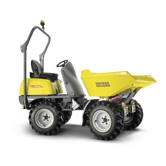
Summary of Contents for Wacker Neuson 1001
- Page 1 Operator's Manual Dumper 1001, 1501, 2001 Machine type D01-04/D01-05/D05-02 Edition Order no 1000184998 Language...
- Page 2 – without prior permission in writing from the manufacturer. No reproduction or translation of this publication, in whole or part, without the written consent of Wacker Neuson Linz GmbH. Violations of legal regulations, in particular of the copyright protection, will be subject to civil and criminal prosecution.
-
Page 3: Table Of Contents
Brief description ....................... 1-2 Regulations ......................1-2 EC declaration of conformity 1001 for all machines delivered before 29 December 2009 EC declaration of conformity 1001 for all machines delivered after 29 December 2009 EC declaration of conformity 1501 for all machines delivered before 29 December 2009... - Page 4 Special instructions for traveling on public roads ..........3-20 Checks before traveling on public roads ............3-20 Starting machine travel ..................3-20 Brake pedal (standard for 1001 + 1501, option for 2001) ........ 3-21 Parking brake ....................3-22 Hazard warning system ..................3-23 Rotating beacon (option) .................
- Page 5 Engine and hydraulics cooling system ..............5-12 Specific safety instructions ................5-12 Checking the coolant level/adding coolant ............5-13 Air filter (1001/1501: up to serial no. EA01742) ............. 5-15 Replacing the filter ................... 5-16 Air filter (1001/1501: from serial no. EA01743) ............5-17 Replacing the air filter ..................
- Page 6 Engine compartment ..................5-31 Threaded fittings and attachments ..............5-31 Pivots and hinges .................... 5-31 Engine/machine fluids and lubricants (1001 and 1501) ......... 5-32 Engine/machine fluids and lubricants (2001) ............5-34 Maintenance plan 1001 – 1501 (overview) ............5-36 Maintenance plan 2001 (overview) ................ 5-39 Lubrication plan 1001/1501H (high-tip skip) ............
- Page 7 Preliminary remark ....................7-1 Designated use ......................7-1 General ........................7-2 Danger zone ......................7-3 Stability ........................7-3 Operation ......................... 7-4 Assembly, maintenance, repair ................7-8 Towing and transporting ..................7-10 Monitoring ......................7-10 BA 1001/1501/2001 us - Edition 3.3 * Ba12001us3_3IVZ.fm...
- Page 8 Maintenance plan ..............5-36 5-39 Pivots and hinges ................. 5-31 Replacing the fuel filter ..............5-9 Servicing and maintenance at regular intervals ......5-28 Threaded fittings ................5-31 Tires ..................... 5-26 V-belt .................... 5-18 BA 1001/1501/2001 us - Edition 3.3 * * Ba12001us3_3SIX.fm...
-
Page 9: Introduction
Insist on using original spare parts when performing maintenance and repair work. This ensures operational safety and readiness of your machine, and maintains its value. Your Wacker Neuson dealer will be happy to answer any further questions regarding the machine or the Operator’s Manual. Abbreviations/symbols •... -
Page 10: Brief Description
• Persons are expected to perform work reliably. They have been appointed by the contractor for driving and servicing the earth moving machine. Get informed on and follow the legal regulations of your country. BA 1001/1501/2001 us – Edition 3.3 * * 12001b110.fm... -
Page 11: Ec Declaration Of Conformity 1001 For All Machines Delivered Before 29 December 2009
Introduction EC declaration of conformity 1001 for all machines delivered before 29 December 2009 EG-Konformitätserklärung Gemäß Maschinen-Richtlinie 98/37/EG, Anhang II A Der Unterzeichnende Wacker Neuson Linz GmbH Haidfeldstraße 37 A-4060 Leonding NEUSON bescheinigt, daß die Baumaschine, Firmenstempel 1. Art Kompakt-Dumper 2. -
Page 12: Ec Declaration Of Conformity 1001 For All Machines Delivered After 29 December 2009
Introduction EC declaration of conformity 1001 for all machines delivered after 29 December 2009 EC Declaration of Conformity According to Machine Directive 2006/42/EC, appendix II A Manufacturer Wacker Neuson Linz GmbH Haidfeldstr. 37 4060 Linz-Leonding Product Machine designation: Compact dumper... -
Page 13: Ec Declaration Of Conformity 1501 For All Machines Delivered Before 29 December 2009
Westendstraße 199 D-80686 München Fachausschuß Tiefbau Die gemeldete Stelle nach Anhang VII Landsbergerstr. 309 D - 80687 München Wurde (wird) eingeschaltet zur Freiwilligen Baumusterprüfung Baumusterprüfbescheinigungs-Nr.: 03154-E Leonding, Ort, Datum Josef Erlinger, Geschäftsführer Unterschrift BA 1001/1501/2001 us – Edition 3.3 * 12001b110.fm... -
Page 14: Ec Declaration Of Conformity 1501 For All Machines Delivered After 29 December 2009
DIN EN ISO 12100-1 and 2, DIN EN 474-1 and 6, DIN EN 14121, DIN EN 3471, DIN EN 13510, EN ISO 3744, EN ISO 3746, DIN EN ISO 3449 Leonding, Thomas Köck, Josef Erlinger, Place, date BA 1001/1501/2001 us – Edition 3.3 * * 12001b110.fm... -
Page 15: Ec Declaration Of Conformity 2001 For All Machines Delivered Before 29 December 2009
Westendstraße 199 D-80686 München Fachausschuß Tiefbau Die gemeldete Stelle nach Anhang VII Landsbergerstr. 309 D - 80687 München Wurde (wird) eingeschaltet zur Freiwilligen Baumusterprüfung Baumusterprüfbescheinigungs-Nr.: 03155-E Leonding, Ort, Datum Josef Erlinger, Geschäftsführer BA 1001/1501/2001 us – Edition 3.3 * 12001b110.fm... - Page 16 DIN EN ISO 12100-1 and 2, DIN EN 474-1 and 6, DIN EN 14121, DIN EN 3471, DIN EN 13510, EN ISO 3744, EN ISO 3746, DIN EN ISO 3449 Leonding, Thomas Köck, Josef Erlinger, Place, date BA 1001/1501/2001 us – Edition 3.3 * * 12001b110.fm...
-
Page 17: Type Labels And Component Numbers
Mass: --------------- Load: --------------- Other information – see chapter 6 Technical data (1001 – 1501) on page 6-1 Fig. 2: Type label (symbolic representation) Engine number The type label (arrow) is located on the cylinder-head cover of the engine. Example: Yanmar 46557 Fig. -
Page 18: Other Signs And Symbols
Machine runs with diesel fuel. Add diesel fuel only! Position On the fuel tank Fig. 7: Fuel tank Meaning Reservoir contains hydraulic oil Position On the hydraulic oil reservoir Fig. 8: Hydraulic oil reservoir 1-10 BA 1001/1501/2001 us – Edition 3.3 * * 12001b110.fm... - Page 19 Machine operation is only allowed if the rollbar is raised and locked, and if the seat belt is fastened. Position On the engine cover Fig. 12: Seat belt (label version 1) 1-11 BA 1001/1501/2001 us – Edition 3.3 * 12001b110.fm...
- Page 20 Fig. 15: Distance from machine Meaning Machine must be towed away only by trained personnel. Follow the instructions in the Operator’s Manual! Position On the engine cover Fig. 16: Towing 1-12 BA 1001/1501/2001 us – Edition 3.3 * * 12001b110.fm...
- Page 21 This label indicates the maximum authorized angle of inclination for traveling on slopes, whatever the position of the machine. Position (2001) Fig. 21: Angle of inclination On the skip Meaning Skip swivel Position (1501S, 2001) On the engine cover Fig. 22: Skip swivel 1-13 BA 1001/1501/2001 us – Edition 3.3 * 12001b110.fm...
- Page 22 At the rear right on the chassis Fig. 23: Loading the dumper Meaning Maintenance prop Position On the front chassis (1001, 1501) and on the swiveling console (2001) Fig. 24: Maintenance prop Meaning Identifies the design-specific machine speed. Position At the rear of the machine (left, right and rear).
-
Page 23: Safety Information
Failure to observe the instructions identified by this symbol can result in damage to the environment. The environment is endangered if environmentally hazardous material, such as waste oil, is not properly used or disposed of. BA 1001/1501/2001 us – Edition 3.3 * 12001b210_us.fm... -
Page 24: Warranty
• Moving earth, gravel, coarse gravel or ballast and rubble • Every other application is regarded as not designated for the use of the machine. Wacker Neuson will not be liable for damage resulting from use other than mentioned above. The user alone will bear the risk. -
Page 25: General Conduct And Safety Instructions
This also applies to the installation and adjustment of safety devices and valves, as well as to welding work on load-bearing elements. • Spare parts must comply with the technical requirements specified by Wacker Neuson. Contact your Wacker Neuson dealer for assistance. -
Page 26: Organizational Measures
Wacker Neuson! This also applies to the installation and the adjustment of safety devices and valves, as well as to welding work on load-bearing elements... -
Page 27: Selection And Qualification Of Staff, Basic Responsibilities
Safety Information • Spare parts must comply with the technical requirements specified by Wacker Neuson. Original spare parts can be relied to do so. • Replace hydraulic hoses within stipulated and appropriate intervals even if no safety- relevant defects have been detected. -
Page 28: Safety Instructions Regarding Operation
• When working in buildings or in enclosed areas, look out for: • Height of the ceiling/clearances • Width of entrances • Maximum load of ceilings and floors • Sufficient room ventilation – poisoning hazard! (exhaust) BA 1001/1501/2001 us – Edition 3.3 * * 12001b210_us.fm... - Page 29 As you raise the skip, watch whether the material is dumped out before fully raising the skip. Failure to watch whether the material is dumped out correctly can cause the dumper to tip over. BA 1001/1501/2001 us – Edition 3.3 * 12001b210_us.fm...
-
Page 30: Operation With Lowered Rollbar
25 % of the payload. However, the towed equipment includ- ing the weight in the skip may not exceed the dumper's payload. Secure the towing pin of the towing gear with a split pin! BA 1001/1501/2001 us – Edition 3.3 * * 12001b210_us.fm... -
Page 31: Staff Qualifications And Basic Responsibilities
The machine will not start unless the parking brake is applied. The drive must be switched off if the parking brake is applied BA 1001/1501/2001 us – Edition 3.3 * 12001b210_us.fm... -
Page 32: Job Site Awareness
(see the turtle indicator light on the instrument panel). • Make sure the engine cover is closed and locked before starting the dumper. 2-10 BA 1001/1501/2001 us – Edition 3.3 * * 12001b210_us.fm... -
Page 33: Carrying Passengers
If necessary, make sure that the machine is in compliance with these regulations. • When crossing underpasses, gates, bridges and tunnels, or when passing under overhead lines, make sure the clearance height and width are sufficient. 2-11 BA 1001/1501/2001 us – Edition 3.3 * 12001b210_us.fm... -
Page 34: Trailering And Transport
The machine may only be used between a maximum +45°C (113°F) and minimum -15°C (5°F). Contact your Wacker Neuson dealer if you intend to use the machine in other temperature ranges. Store the machine in a dry place at room temperature (about 15°C, or 59°F). -
Page 35: Personal Safety Measures
• Do not allow the machine to be serviced, repaired, or test-traveled by unauthorized staff. • If maintenance with the engine running cannot be avoided, lower the skip and apply the parking brake. 2-13 BA 1001/1501/2001 us – Edition 3.3 * 12001b210_us.fm... -
Page 36: Special Hazards
• Observe the operating voltage of the machine/attachments. • Always remove the grounding strap from the battery when working on the electric system. 2-14 BA 1001/1501/2001 us – Edition 3.3 * * 12001b210_us.fm... -
Page 37: Gas, Dust, Steam, Smoke
• Be careful when handling hot consumables – burn hazard! MSDS • When handling oil, grease and other chemical substances such as battery electrolyte or hydraulic fluid, observe the product-related safety regulations (Material Safety Data Sheet: MSDS). 2-15 BA 1001/1501/2001 us – Edition 3.3 * 12001b210_us.fm... -
Page 38: Tires (Wheel Dumpers)
• Do not operate a machine when its fuel cap is loose or missing. • Do not remove the radiator cap when the engine is running or hot. The radiator fluid is hot and under pressure, and may cause severe burns! 2-16 BA 1001/1501/2001 us – Edition 3.3 * * 12001b210_us.fm... -
Page 39: Guidelines For Fueling The Engine
• Replace the fuel tank cap after refueling. When fueling the engine: • Do not smoke. • Do not refuel a hot or running engine. • Do not refuel the engine near an open flame. 2-17 BA 1001/1501/2001 us – Edition 3.3 * 12001b210_us.fm... - Page 40 Safety Information 2-18 BA 1001/1501/2001 us – Edition 3.3 * * 12001b210_us.fm...
-
Page 41: Operation
Identifies an activity Description of the effects or results of an activity n. s. = not shown Opt = option Stated whenever controls or other components of the machine are installed as an option. BA 1001/1501/2001 us – Edition 3.3 * 12001b320.fm... -
Page 42: Description Of 1001/1501 Components (Overview)
Description of 1001/1501 components (overview) Pos. Designation Rear chassis Front chassis Lift frame Articulated joint Operator seat Control stand Tilt console Engine cover Parallel lift Skip Lift cylinder Tilt cylinder (not shown) Steering cylinder BA 1001/1501/2001 us – Edition 3.3 * * 12001b320.fm... -
Page 43: Description Of 1501S Components (Overview)
Operation Description of 1501S components (overview) Pos. Designation Operator seat Control stand Skip Swivel centring Swiveling console Tilt cylinder Articulated joint Steering cylinder Rear chassis Engine cover BA 1001/1501/2001 us – Edition 3.3 * 12001b320.fm... -
Page 44: Description Of 2001S Components (Overview)
Description of 2001S components (overview) Pos. Designation Rear chassis Front chassis Swiveling console Articulated joint Operator seat Control stand Mudguard Engine cover Swivel centring Skip Swiveling cylinder Tilt cylinder Steering cylinder Rollbar BA 1001/1501/2001 us – Edition 3.3 * * 12001b320.fm... -
Page 45: Description Of 2001 Sle Components
Operation Description of 2001 SLE components Pos. Designation Lift frame Lift cylinder Bucket cylinder Bucket Fastening mount Articulation (large) Articulation (small) BA 1001/1501/2001 us – Edition 3.3 * 12001b320.fm... -
Page 46: 1001/1501/1501S Operating Equipment Up To Serial No. Ab
Operation 1001/1501/1501S operating equipment up to serial no. AB ... Driving direction lever Pos. Designation Accelerator pedal Hour meter Parking brake Fuel level indicator Preheating start switch Lever “Tilting out/lowering the skip” Travel direction lever Lever “Raising/lowering the skip” Horn... -
Page 47: 1001/1501/1501S Operating Equipment From Serial No. Ab
Operation 1001/1501/1501S operating equipment from serial no. AB ... Pos. Designation Accelerator pedal Hydraulic oil filter indicator light Service brake Preheating indicator light Parking brake Hour meter Preheating start switch Fuel level indicator Travel direction lever Lever “Tilting out/lowering the skip”... -
Page 48: 2001/2001Sle Operating Equipment
Lever: swivel skip Engine temperature indicator light Hydrostatic brake pedal Spare fuel indicator light Light switch Not assigned Seat adjustment lever Hydraulic oil filter indicator light Skip/loader unit switch (option 2001) Not assigned BA 1001/1501/2001 us – Edition 3.3 * * 12001b320.fm... -
Page 49: Putting Into Operation
• Do not run the engine at high speed for extended periods • Increase the load gradually while varying the engine speed • Strictly observe the maintenance schedules in the appendix – see chapter 5.16 Maintenance plan 2001 (overview) on page 5-39 BA 1001/1501/2001 us – Edition 3.3 * 12001b320.fm... -
Page 50: Check Lists
Especially after cleaning, maintenance or repair work: Rags, tools and other loose objects removed? 15 Seating position adjusted correctly? ( 3-27) 16 Rollbar raised and locked? 17 Seat belt fastened? ( 3-28) 3-10 BA 1001/1501/2001 us – Edition 3.3 * * 12001b320.fm... -
Page 51: Operation Checklist
Parking brake applied? Starting key removed? When parking on public roads: Machine adequately secured? When parking on slopes: Machine additionally secured with chocks under the wheels to prevent it from rolling away? 3-11 BA 1001/1501/2001 us – Edition 3.3 * 12001b320.fm... -
Page 52: Machine Travel
• Speed can be set continuously with accelerator pedal 25 Press down the accelerator pedal: Engine speed rises Reduce the pressure on the accelerator pedal: Engine speed is reduced Fig. 27: Accelerator pedal (symbolic representation) 3-12 BA 1001/1501/2001 us – Edition 3.3 * * 12001b320.fm... -
Page 53: Indicator Lights And Warning Lights (Overview)
If the indicator light illuminates with the engine running: Stop the engine immediately and Have the cause repaired by a Wacker Neuson service center The V-belt is malfunctioning or there is an error in the charging circuit of the alternator if the indicator light illuminates with the engine running. - Page 54 Counts the engine operating hours with the engine running. 17 Fuel level indicator Refuel immediately if the fuel level indicator reaches minimum. Otherwise the fuel system must be bled if it is run dry. 3-14 BA 1001/1501/2001 us – Edition 3.3 * * 12001b320.fm...
-
Page 55: Mirrors (Option)
• Ensure sufficient visibility from the operator seat onto the job site. • Ensure maximum visibility to the rear. • Ensure visibility of the rear edges of the machine in the mirrors. Fig. 26: Mirrors (symbolic representation) 3-15 BA 1001/1501/2001 us – Edition 3.3 * 12001b330.fm... -
Page 56: Stvo Accessories (Option)
General information on starting the engine Important The model 1001 and 1501 engine will not start unless the parking brake is applied and the brake pedal is pressed at the same time. • 1001: from serial no. EA03289. -
Page 57: Procedure
If the engine still does not start after the second try Contact a Wacker Neuson service center for troubleshooting. As soon as the engine runs: Release the starting key When the engine runs smoothly (increased engine speed): Fig. 28: Indicator lights 3-17 BA 1001/1501/2001 us – Edition 3.3 * 12001b330.fm... -
Page 58: Travel Interlock
Insert the master key in the starter and turn it to position 1 for at least 20 seconds. The coded keys are deleted now. New or existing keys have to be recoded. 3-18 BA 1001/1501/2001 us – Edition 3.3 * * 12001b330.fm... -
Page 59: When The Engine Has Started
With the engine running, disconnect both jump leads in exactly the reverse order (first 12 V – remove the terminal, then the terminal) – this prevents sparking near the battery! Starting battery Fig. 31: Starting aid with battery jumper cables 34001b710_05.eps 3-19 BA 1001/1501/2001 us – Edition 3.3 * 12001b330.fm... -
Page 60: Special Instructions For Traveling On Public Roads
WARNING Accident hazard due to traveling direction changeover dur- ing machine travel! Can cause severe injury or death. • Stop the machine and activate the brake during travel direction changeover. 3-20 BA 1001/1501/2001 us – Edition 3.3 * * 12001b330.fm... -
Page 61: Brake Pedal (Standard For 1001 + 1501, Option For 2001)
The speed with which the skip moves also depends on the position of the accelerator pedal. Fig. 33: Accelerator pedal (symbolic representation) Brake pedal (standard for 1001 + 1501, option for 2001) The machine brakes automatically to a standstill when releasing the accelerator pedal. -
Page 62: Parking Brake
Fig. 36: Parking brake 1001/1501 (symbolic representation) 2001: To apply: pull lever 10 upward. To release: press and hold button 21, then lower lever 10 completely. Fig. 37: Parking brake 2001 3-22 BA 1001/1501/2001 us – Edition 3.3 * * 12001b330.fm... -
Page 63: Hazard Warning System
Always travel straight ahead when driving uphill or downhill. Driving diagonally or at an angle to the slope is very dangerous. Travel slowly in meadows, on leaves or wet steel plates. The machine can slip even if the ground is level. 3-23 BA 1001/1501/2001 us – Edition 3.3 * 12001b330.fm... -
Page 64: Driving On Slopes With A Loaded Skip
Accident hazard due to tipping over or slipping of the machine on slopes! Can cause severe injury or death. • Machine travel across slopes (max. inclination up to 20 %) is allowed only on firm ground. 3-24 BA 1001/1501/2001 us – Edition 3.3 * * 12001b330.fm... -
Page 65: Parking The Machine
Never stop the engine under full load, otherwise it can be damaged due to overheating. Let the engine briefly run at idling speed with no load before you switch it off. Important Secure the machine against unauthorized operation. • Remove the key. 3-25 BA 1001/1501/2001 us – Edition 3.3 * 12001b330.fm... -
Page 66: Loading The Machine
Apply the parking brake Stay clear of the control stand and the danger zone • Once loading is over: Remove dirt, debris, dust, etc. from the control elements Remove loose material 3-26 BA 1001/1501/2001 us – Edition 3.3 * * 12001b330.fm... -
Page 67: Seat Adjustment
Backrest adjustment Pull lever 29 up and at the same time press against the backrest to move it to the required position. Let lever 29 lock into place. Fig. 45: Backrest adjustment 3-27 BA 1001/1501/2001 us – Edition 3.3 * 12001b330.fm... -
Page 68: Seat Belt
• Hold belt on buckle latch A and run it slowly and steadily over the hips to buckle B • Insert buckle latch A into buckle B with an audible click (pull test) Fig. 46: Fastening the seat belt 3-28 BA 1001/1501/2001 us – Edition 3.3 * * 12001b330.fm... -
Page 69: Engine Cover
The engine cover can be locked in eyelet D with an external lock Important Do not lock the engine cover during machine operation since the emergency switch is located under the engine cover. Fig. 48: Engine cover lock 3-29 BA 1001/1501/2001 us – Edition 3.3 * 12001b330.fm... -
Page 70: Working With The Machine
Secure the edge of the pit with a wooden beam anchored in the ground. NOTICE Lowering the skip too rapidly and knocking it against the chassis can cause damage. 3-30 BA 1001/1501/2001 us – Edition 3.3 * * 12001b330.fm... -
Page 71: Skip Operation
Lever to the rear Lowers the skip Lever to the left Skip is rotated to the left Lever to the right Skip is rotated to the right Fig. 51: Swivel skip operation (2001) 3-31 BA 1001/1501/2001 us – Edition 3.3 * 12001b330.fm... -
Page 72: Swivel Skip And Loader Unit Operation (2001Sle)
Raises the lift frame and tilts in the bucket Lever to the right and front Lowers the lift frame and tilts out the bucket Fig. 55: Loader unit operation (2001) 3-32 BA 1001/1501/2001 us – Edition 3.3 * * 12001b330.fm... -
Page 73: Loader Unit (Option 2001)
• Position the loader unit in the rear end position on the skip before traveling. Important Grease all lubrication points of the loader unit daily. Fig. 56: Loader unit (option 2001) 3-33 BA 1001/1501/2001 us – Edition 3.3 * 12001b330.fm... -
Page 74: Rollbar
Slowly and carefully lower the rollbar with the help of a second person. Raising the rollbar: Park the machine on horizontal ground. Raise the rollbar. Fasten the rollbar with lock pins A and secure these pins with split pins. Fig. 57: Rollbar 3-34 BA 1001/1501/2001 us – Edition 3.3 * * 12001b330.fm... -
Page 75: Towing 1001/1501/2001
You can now slowly tow the machine (max. 2 kph/1.2 mph) over a short distance (max. 1 km/0.6 miles). Important After towing the machine, the pressure must be set and the machine put back into operation by a Wacker Neuson service center. 3-35 BA 1001/1501/2001 us – Edition 3.3 * 12001b330.fm... -
Page 76: Releasing The Hydraulic Parking Brake 1001/1501
1 km/0.6 miles). Important Fig. 60: Opening the high-pressure circuit After towing the machine, the pressure must be set and the machine put back into operation by a Wacker Neuson service center. 3-36 BA 1001/1501/2001 us – Edition 3.3 * * 12001b330.fm... -
Page 77: Releasing The Hydraulic Parking Brake 2001
Remove the plastic plugs (4) in the middle on the face of the wheel motors. Place the extraction unit on the face of the wheel motor and fasten it with screw M12x35. Tighten the screw to 42 Nm (31 ft.lbs) until the wheel turns freely. 3-37 BA 1001/1501/2001 us – Edition 3.3 * 12001b330.fm... -
Page 78: Center-Pivot Prop
Lock the control levers for the skip during road travel. This avoids unintentional actuation of the skip. Locking the control levers (1001/1501) Fold back control lever lock A. Fig. 62: Locking the control levers (1001/1501) 3-38 BA 1001/1501/2001 us – Edition 3.3 * * 12001b330.fm... -
Page 79: Locking The Control Levers (2001)
Locking the control levers (2001) Fold back control lever lock A. Fig. 64: Locking the control levers (2001) Fasten control lever lock A with split pin B. Fig. 65: Locking the control levers (2001) 3-39 BA 1001/1501/2001 us – Edition 3.3 * 12001b330.fm... -
Page 80: Lifting The Machine
Locking the control levers on page 3-38 • The rollbar can be lowered to reduce the transport height. • Put the cente-pivot prop in place • Use suitable lifting gear, chains, etc. 3-40 BA 1001/1501/2001 us – Edition 3.3 * * 12001b330.fm... -
Page 81: Loading And Transporting The Machine
• Ensure that the ramps and the tires of the dumper are free of oil, grease and ice Fig. 68: Access ramps • Start the engine of the dumper • Lower the skip of the dumper • Carefully reverse the dumper onto the middle of the transport vehicle 3-41 BA 1001/1501/2001 us – Edition 3.3 * 12001b330.fm... -
Page 82: Tying Down The Machine
Insert key A in the battery master switch Turn the key down to the notched position C The 2001 dumper has a Quickpower Plus terminal instead of a main switch 3-42 BA 1001/1501/2001 us – Edition 3.3 * * 12001b330.fm... -
Page 83: Malfunctions
Insufficient or no engine oil pressure Machine inclination too high (max. 25°) Wrong SAE grade of engine lubrication oil 5-32 Oil level too high 5-10 Engine oil consumption too high Machine inclination too high (max. 25°) BA 1001/1501/2001 us – Edition 3.3 * 12001b410.fm... - Page 84 Engine starting temperature too low Fuel grade does not comply with specifications 5-32 White Engine smoke Wrong valve clearance Malfunctioning fuel injector Dirty air filter 5-15 Black Wrong valve clearance Malfunctioning fuel injector BA 1001/1501/2001 us – Edition 3.3 * * 12001b410.fm...
-
Page 85: Maintenance
All other maintenance must be per- formed by trained and qualified personnel only. The maintenance plans indicate when the maintenance mentioned below must be per- formed – see Maintenance plan 2001 (overview) on page 5-39. BA 1001/1501/2001 us – Edition 3.3 * 12001b510.fm... -
Page 86: Brake Test
Important Do not put the machine into operation if a brake test gives a negative result or if there are doubts as to the correct brake function. Contact a Wacker Neuson service center and have the malfunction rectified. The following tests are performed to check the brake function on firm, level and horizontal ground. -
Page 87: High-Tip Skip Maintenance Prop (1001/1501H)
Remove split pin B and pin C. Fig. 73: Swivel skip maintenance prop 1501S Slowly lower the skip until maintenance prop A is firmly in its position. Fig. 74: Swivel skip maintenance prop 1501S BA 1001/1501/2001 us – Edition 3.3 * 12001b510.fm... -
Page 88: Swivel Skip Maintenance Prop 2001S
Remove split pin B and pin C. Fig. 75: Swivel skip maintenance prop 2001S Slowly lower the skip until maintenance prop A is firmly in its position. Fig. 76: Swivel skip maintenance prop 2001S BA 1001/1501/2001 us – Edition 3.3 * * 12001b510.fm... -
Page 89: Fuel System
Refueling Filler inlet A for the fuel tank is located under the engine cover, on the right in driving direction. Fig. 77: Fuel filler inlet 1001/1501 Fig. 77: Fuel filler inlet 2001 BA 1001/1501/2001 us – Edition 3.3 * 12001b510.fm... - Page 90 Fill up the tank with the correct fuel type at the end of each working day. This prevents condensation water from forming in the fuel tank over night. Do not fill the tank completely but leave some space for the fuel to expand. BA 1001/1501/2001 us – Edition 3.3 * * 12001b510.fm...
-
Page 91: Stationary Fuel Pumps
• After removing and fitting the fuel filter, prefilter or the fuel lines back on again • After running the fuel tank empty • After running the engine again, after it has been out of service for a longer period of time BA 1001/1501/2001 us – Edition 3.3 * 12001b510.fm... -
Page 92: Fuel Prefilter With Water Separator
Fuel supply is open again Environment Use a suitable container to collect fluids and lubricants as they flow out and dispose of them in an environmentally friendly manner. Fig. 79: Fuel prefilter BA 1001/1501/2001 us – Edition 3.3 * * 12001b510.fm... -
Page 93: Replacing The Fuel Filter
Bleeding the fuel system on page 5-7 Make a test run – and check for tightness! Dispose of the old fuel filter cartridge by an ecologically safe method Fig. 80: Fuel filter 1001/1501 Fig. 80: Fuel filter 2001 BA 1001/1501/2001 us – Edition 3.3 * 12001b510.fm... -
Page 94: Engine Lubrication System
NOTICE Engine damage and loss of output in case of insufficient engine oil level, or wrong engine oil! Have the oil changed by a Wacker Neuson service center – see chapter 5.16 Maintenance plan 2001 (overview) on page 5-39 Important In order to avoid engine damage, add the engine oil slowly so it can go down without entering the intake system. -
Page 95: Adding Engine Oil
• Add oil if necessary and check the oil level again • Close filler cap B • Push oil dipstick A back in as far as possible • Completely remove all oil spills from the engine Fig. 82: Adding engine oil 5-11 BA 1001/1501/2001 us – Edition 3.3 * 12001b510.fm... -
Page 96: Engine And Hydraulics Cooling System
Let the engine cool down Check the coolant level again Environment Use a suitable container to collect fluids and lubricants as they flow out and dispose of them in an environmentally friendly manner. 5-12 BA 1001/1501/2001 us – Edition 3.3 * * 12001b510.fm... -
Page 97: Checking The Coolant Level/Adding Coolant
Can cause severe injury or death. • Keep away from flames. • Avoid eye contact with antifreeze. • If antifreeze comes into contact with the eyes: • immediately rinse with clean water and seek medical assistance. 5-13 BA 1001/1501/2001 us – Edition 3.3 * 12001b510.fm... - Page 98 Engine/machine fluids and lubricants (1001 and 1501) on page 5-32 – see chapter 5.14 Engine/machine fluids and lubricants (2001) on page 5-34. Important Check the antifreeze every year before the cold season sets in! 5-14 BA 1001/1501/2001 us – Edition 3.3 * * 12001b510.fm...
-
Page 99: Air Filter (1001/1501: Up To Serial No. Ea01742)
Maintenance Maintenance Air filter (1001/1501: up to serial no. EA01742) NOTICE The filter cartridge will be damaged if it is washed or brushed out! Bear in mind the following to avoid premature engine wear! Do not clean the filter cartridge... -
Page 100: Replacing The Filter
Carefully insert the new filter B in the air filter housing Position lower housing section E (ensure that it is properly seated) Close both bow clips D Fig. 86: Removing the filter element 5-16 BA 1001/1501/2001 us – Edition 3.3 * * 12001b520.fm... -
Page 101: Air Filter (1001/1501: From Serial No. Ea01743)
Close bow clips D. Ensure that dust valve F shows downward once it is installed. After replacing the filters, press button J to reset the yellow piston B. Fig. 93: Inside filter 5-17 BA 1001/1501/2001 us – Edition 3.3 * 12001b520.fm... -
Page 102: V-Belt
CAUTION Cracked and stretched V-belts cause engine damage. Have the V-belt replaced by a Wacker Neuson service center Check the V-belt once a day or every 10 operating hours, and retighten it if necessary. Retighten new V-belts after about 15 minutes of running time. -
Page 103: Retightening The V-Belt
Keep the alternator in this position, and at the same time retighten fastening screws 2 Check V-belt tension again and adjust it if necessary Connect the battery or the battery master switch Close the engine cover Fig. 96: Retightening the V-belt 5-19 BA 1001/1501/2001 us – Edition 3.3 * 12001b520.fm... -
Page 104: Hydraulic System
Otherwise, follow-on damage can result! Environment Use a suitable container to collect fluids and lubricants as they flow out and dispose of them in an environmentally friendly manner. 5-20 BA 1001/1501/2001 us – Edition 3.3 * * 12001b520.fm... -
Page 105: Checking The Hydraulic Oil Level
(between 122 and 194 °F) Fig. 97: Oil level indicator on the hydraulic oil reservoir 2001 Important Measure the oil level of the hydraulic system only after the machine reaches its operating temperature. 5-21 BA 1001/1501/2001 us – Edition 3.3 * 12001b520.fm... -
Page 106: Adding Hydraulic Oil
• Add hydraulic oil • Check the hydraulic oil level on sight glass A Fig. 98: Hydraulic oil reservoir • Add if necessary and check again • Firmly tighten plug B 5-22 BA 1001/1501/2001 us – Edition 3.3 * * 12001b520.fm... -
Page 107: Changing Hydraulic Oil
Remove the filter element from the filler pipe and dispose of it Slide the filler pipe onto the new filter element and insert it in the filter Tighten the cover by hand Fig. 100: Hydraulic return filter 5-23 BA 1001/1501/2001 us – Edition 3.3 * 12001b520.fm... -
Page 108: Important Information On The Use Of Biodegradable Oil
• Use only the biodegradable hydraulic fluids which have been tested and approved by Wacker Neuson GmbH. Always contact Wacker Neuson for the use of other products that have not been recommended. In addition, ask the oil supplier for a written decla- ration of guarantee. -
Page 109: Checking Hydraulic Pressure Lines
• Use paper or wood to check for minor leaks. Never use an unprotected light or open flame! • Have damaged flexible lines replaced by a Wacker Neuson service cen- ter only! • Leaks and damaged pressure lines must be immediately repaired or replaced by a Wacker Neuson service center or after-sales personnel. -
Page 110: Tires
Can cause severe injury or death. • All repair work on tires and rims may only be performed by a Wacker Neuson service center. We recommend checking the tires for wear and the wheel nuts for tightness once a day. -
Page 111: Wheel Change
Lower the raised axle Tighten the wheel nuts to 200 Nm (148 ft.lbs) Important Subsequent to changing wheels check the wheel nuts for tightness after 10 operating hours – tighten if necessary! 5-27 BA 1001/1501/2001 us – Edition 3.3 * 12001b530.fm... -
Page 112: Electrical System
• Is the signaling and warning system OK? Every week Check once a week: • Cable and grounding connections • Battery charge condition – see Battery on page 5-29 • Condition of battery terminals 5-28 BA 1001/1501/2001 us – Edition 3.3 * * 12001b530.fm... -
Page 113: Instructions Concerning Specific Components
Checking the battery requires it to be removed and must be performed by a Wacker Neu- son service center. Always follow the specific battery safety instructions! Important Do not disconnect the battery while the engine is running! Fig. 102: Battery 5-29 BA 1001/1501/2001 us – Edition 3.3 * 12001b530.fm... -
Page 114: General Maintenance
• Air intake filters, etc. Cleaning with volatile and easily flammable anticorrosion agents and sprays: • Ensure adequate room ventilation • Do not use unprotected lights or open flames • Do not smoke! 5-30 BA 1001/1501/2001 us – Edition 3.3 * * 12001b530.fm... -
Page 115: Threaded Fittings And Attachments
Fastening screws on the hydraulic system Line and pin fastenings on the attachment Retighten loose connections immediately. Contact a Wacker Neuson service center if necessary. Pivots and hinges Lubricate all mechanical pivots on the machine (such as joints) and fittings at regular inter- vals even if they are not listed in the lubrication plan. -
Page 116: Engine/Machine Fluids And Lubricants (1001 And 1501)
Biodegradable hydraulic oil based on saturated synthetic esters with an iodine value of < 10, according to DIN 51524, section 3, HVLP, HEES KF2K-25 according to DIN 51502 multipurpose lithium grease with MoS² additive Standard acid-proof grease 1001: up to serial no. WNCD0104PPAL00399/1501: up to serial no. WNCD0105APAL00399 1001: from serial no. WNCD0104HPAL00400/1501: from serial no. WNCD0105KPAL00400 5-32... - Page 117 Engine oil grade Ambient temperature (°C) °C SAE 10W SAE 20W SAE 10W-30 SAE 10W-40 API CD, CF, CF-4, CI-4 SAE 15W-40 ACEA: E3, E4, E5 SAE 20 SAE 30 SAE 40 °F 5-33 BA 1001/1501/2001 us – Edition 3.3 * 12001b530.fm...
-
Page 118: Engine/Machine Fluids And Lubricants (2001)
Biodegradable hydraulic oil based on saturated synthetic esters with an iodine value of < 10, according to DIN 51524, section 3, HVLP, HEES Standard acid-proof grease First replacement after 50 operating hours Up to serial no. WNCD0502APAL00299 From serial no. WNCD0502KPAL00300 5-34 BA 1001/1501/2001 us – Edition 3.3 * * 12001b530.fm... - Page 119 Oil grades for the diesel engine, depending on temperature Engine oil grade Ambient temperature (°C) °C SAE 10W SAE 20W SAE 10W-30 SAE 10W-40 API: CH4, CE/SJ SAE 15W-40 ACEA: A3, B3, E3 SAE 20 SAE 30 SAE 40 5-35 BA 1001/1501/2001 us – Edition 3.3 * 12001b530.fm...
- Page 120 Maintenance Wacker Neuson service center Customer Every 1000 o/h once a year Every 500 o/h Every 50 o/h Maintenance (once a day) 5-36 BA 1001/1501/2001 us – Edition 3.3 * * 12001b540.fm...
- Page 121 Maintenance Wacker Neuson service center Customer Every 1000 o/h once a year Every 500 o/h Every 50 o/h Maintenance (once a day) 5-37 BA 1001/1501/2001 us – Edition 3.3 * * 12001b540.fm...
- Page 122 Maintenance Wacker Neuson service center Customer Every 1000 o/h once a year Every 500 o/h Every 50 o/h Maintenance (once a day) 5-38 BA 1001/1501/2001 us – Edition 3.3 * * 12001b540.fm...
- Page 123 Maintenance Wacker Neuson service center Customer After 1500 o/h Once a year or after 1000 o/h Every 500 o/h Every 250 o/h Every 50 o/h Maintenance (once a day) 5-39 BA 1001/1501/2001 us – Edition 3.3 * * 12001b540.fm...
- Page 124 Maintenance Wacker Neuson service center Customer After 1500 o/h Once a year or after 1000 o/h Every 500 o/h Every 250 o/h Every 50 o/h Maintenance (once a day) 5-40 BA 1001/1501/2001 us – Edition 3.3 * * 12001b540.fm...
- Page 125 Maintenance Wacker Neuson service center Customer After 1500 o/h Once a year or after 1000 o/h Every 500 o/h Every 250 o/h Every 50 o/h Maintenance (once a day) 5-41 BA 1001/1501/2001 us – Edition 3.3 * * 12001b540.fm...
-
Page 126: Lubrication Plan 1001/1501H (High-Tip Skip)
Maintenance Maintenance 5.17 Lubrication plan 1001/1501H (high-tip skip) Lower the red maintenance prop before performing maintenance with a raised lift frame – High-tip skip maintenance prop (1001/1501H) on page 5-3. 5-42 BA 1001/1501/2001 us – Edition 3.3 * * 12001b560.fm... - Page 127 Designation Interval Quantity Accelerator pedal Daily Steering cylinder Daily Articulated joint (vertical) Daily Articulated joint (horizontal) Daily Lift cylinder Daily Connecting rods Daily Lift frame Daily Skip Daily Tilt cylinder Daily 5-43 BA 1001/1501/2001 us – Edition 3.3 * 12001b560.fm...
-
Page 128: Lubrication Plan 1501S (Swivel Skip)
5.18 Lubrication plan 1501S (swivel skip) Lower the red maintenance prop before performing maintenance with a raised lift frame – see chapter Swivel skip maintenance prop (1501S/option) on page 5-3 5-44 BA 1001/1501/2001 us – Edition 3.3 * * 12001b560.fm... - Page 129 Designation Interval Quantity Accelerator pedal Daily Steering cylinder Daily Articulated joint (vertical) Daily Articulated joint (horizontal) Daily Swiveling cylinder Daily Swivel lock Daily Live ring Daily Tilt cylinder Daily Skip Daily 5-45 BA 1001/1501/2001 us – Edition 3.3 * 12001b560.fm...
-
Page 130: Lubrication Plan 2001 (Swivel Skip)
5.19 Lubrication plan 2001 (swivel skip) Lower the red maintenance prop before performing maintenance with a raised lift frame – see chapter Swivel skip maintenance prop 2001S on page 5-4. 5-46 BA 1001/1501/2001 us – Edition 3.3 * * 12001b560.fm... - Page 131 Grease nipple B is located under base plate A. Removing it requires opening the engine cover first – see chapter Engine cover on page 3-29 Remove the screws of the base plate with a suitable tool and apply grease to grease nipple B 5-47 BA 1001/1501/2001 us – Edition 3.3 * 12001b560.fm...
- Page 132 Maintenance 5-48 BA 1001/1501/2001 us – Edition 3.3 * * 12001b560.fm...
-
Page 133: Technical Data (1001 - 1501)
Glow plug (preheating time 10 – 15 sec- Starting aid Glow plugs (preheating time 4 seconds) onds) Specific fuel consumption 279 g/kWh (0.615 lb/hph) 272 g/kWh (0.599 lb/hph) Exhaust values according to 97/68/EC EPA Tier II BA 1001/1501/2001 us – Edition 3.3 * 12001b610.fm... -
Page 134: Traveling Drive 1001
Hydraulic parking brake for auxiliary brake and parking brake with Effect hand brake valve control Steering system Model 1001/1501/1501S Steering system Hydrostatic chassis articulation steering with Design emergency steering features. Chassis articulation steering Steering mode BA 1001/1501/2001 us – Edition 3.3 * * 12001b610.fm... -
Page 135: Operating Hydraulics
+/− 15° Oscillation 3200 mm (10'-6'') 3500 mm (11'-6") Outside turning radius 45 % 45 % Hill climbing ability 20 % in all directions 20 % in all directions Safe authorized inclination BA 1001/1501/2001 us – Edition 3.3 * 12001b610.fm... -
Page 136: Electrical System
– Start interlock relay – Regulator Fig. 104: Relays – Main fuse Fuse box (from AB150001H/150002D) The fuse box is located on the right of the machine under the engine cover (see arrow). BA 1001/1501/2001 us – Edition 3.3 * * 12001b610.fm... -
Page 137: Relays (From Ab150001H/150002D)
K 32 – Start interlock relay K34 K33 K32 Fig. 106: Relays K 33 – Low beam relay K 34 – High beam relay – Diodes F 1, 2 – Main fuses BA 1001/1501/2001 us – Edition 3.3 * 12001b610.fm... -
Page 138: Tires 1001/1501
Uncertainty of measurement K has been taken into account for the specified values. The degree of vibration is influenced by various parameters. Some of them are listed below: • Operator: training, behavior, working method and strain. BA 1001/1501/2001 us – Edition 3.3 * * 12001b610.fm... - Page 139 • Travel around obstacles and uneven ground. • Reduce your speed when traveling across rough terrain. • Reduce vibration to a minimum during long work cycles or when traveling over long distances: BA 1001/1501/2001 us – Edition 3.3 * 12001b610.fm...
- Page 140 Coucil on minimum health and safety requirements regarding exposure of workers to risks arising from physical agents (vibration). Your Wacker Neuson dealer provides information on other machine functions reducing vibration and on safe operation. BA 1001/1501/2001 us – Edition 3.3 * * 12001b610.fm...
-
Page 141: Dimensions Model 1001
Overall height without rollbar 1180 mm (46 in) Overall width 990 mm (39 in) Overall width (narrow version) 270 mm (11 in) Ground clearance 1500 mm (59 in) Wheelbase 3200 mm (10'-6'') Outside turning radius BA 1001/1501/2001 us – Edition 3.3 * 12001b610.fm... -
Page 142: Dimensions Model 1501
1850 mm (73 in) Overall height without rollbar 1305 mm (51 in) Overall width 270 mm (11 in) Ground clearance 1650 mm (65 in) Wheelbase 3300 mm (10'-10'') Outside turning radius 6-10 BA 1001/1501/2001 us – Edition 3.3 * * 12001b610.fm... -
Page 143: Dimensions Model 1501S
1850 mm (73 in) Overall height without rollbar 1305 mm (51 in) Overall width 270 mm (11 in) Ground clearance 1700 mm (67 in) Wheelbase 3300 mm (10'-10'') Outside turning radius 6-11 BA 1001/1501/2001 us – Edition 3.3 * 12001b610.fm... -
Page 144: Technical Data (2001)
(as seen from the flywheel) Glow plug (preheating time Glow elements (preheating Starting aid 10 – 15 seconds) time 10 – 15 seconds) 97/68/EG 97/68/EC EPA Exhaust values according to EPA II 6-12 BA 1001/1501/2001 us – Edition 3.3 * * 12001b610.fm... -
Page 145: Traveling Drive
2 sections Control valve 175 bar (2,538 psi) Max. operating pressure 160 bar (2,321 psi) Secondary pressure limiting for swiveling cylinder Standard Hydraulic oil radiator 28 l (7.4 gal) Hydraulic reservoir capacity 6-13 BA 1001/1501/2001 us – Edition 3.3 * 12001b610.fm... -
Page 146: Loader Unit
– Cutoff solenoid 20 A – 12 V/30 10 A – Start clearance, fuel pump 10 A – Horn, brake lights, brake valve 10 A – Hazard warning system (permanent plus) 6-14 BA 1001/1501/2001 us – Edition 3.3 * * 12001b610.fm... -
Page 147: Relays
Start clearance relay No function Turn indicator relay Fig. 111: Relay box 2001 Pull contact high current relay Preheating time lag relay Pull contact time lag relay Start high-current relay Diode box 6-15 BA 1001/1501/2001 us – Edition 3.3 * 12001b610.fm... -
Page 148: Tires
Uncertainty of measurement K has been taken into account for the specified values. The degree of vibration is influenced by various parameters. Some of them are listed below: • Operator: training, behavior, working method and strain. 6-16 BA 1001/1501/2001 us – Edition 3.3 * * 12001b610.fm... - Page 149 • Travel around obstacles and uneven ground. • Reduce your speed when traveling across rough terrain. • Reduce vibration to a minimum during long work cycles or when traveling over long distances: 6-17 BA 1001/1501/2001 us – Edition 3.3 * 12001b610.fm...
- Page 150 For more information on vibration, refer to Directive 2002/44/EC of European Parliament and Coucil on minimum health and safety requirements regarding exposure of workers to risks arising from physical agents (vibration). Your Wacker Neuson dealer provides information on other machine functions reducing vibration and on safe operation. 6-18...
-
Page 151: Dimensions Model 2001
380 mm (15 in) Ground clearance 1800 mm (71 in) Wheelbase 3500 mm (11'-6'') Outside turning radius 45 % theoretically Hill climbing ability 20 % in all machine travel Safe authorized inclination positions 6-19 BA 1001/1501/2001 us – Edition 3.3 * 12001b610.fm... - Page 152 Technical data (2001) 6-20 BA 1001/1501/2001 us – Edition 3.3 * * 12001b610.fm...
-
Page 153: Safety Instructions For Operation Of Earth Moving Machines
Spare parts must comply with the technical requirements specified by the manufacturer. 7.2.5 The loader unit has been designed for loading up to 300 kg of material (bulk mate- rial, for example) without any assistance. BA 1001/1501/2001 us – Edition 3.3 * 12001b710.fm... -
Page 154: General
7.3.13 Secure loose parts, such tools or other equipment, on the earth moving machine. 7.3.14 Secure open doors, windows, covers, lids, etc., to prevent them from closing unin- tentionally. BA 1001/1501/2001 us – Edition 3.3 * * 12001b710.fm... -
Page 155: Danger Zone
7.5.5 When driving or working near excavations, shafts, trenches or the edge of pits and embankments, secure the earth moving machine to prevent it slipping or rolling away. BA 1001/1501/2001 us – Edition 3.3 * 12001b710.fm... -
Page 156: Operation
7.6.3.9 Do not drive downhill with the clutch disengaged. Shift to a gear adapted to the ter- rain before driving down a slope, and do not shift gears on the slope. BA 1001/1501/2001 us – Edition 3.3 * * 12001b710.fm... - Page 157 7.6.6.5 If possible, the highest point of the work equipment of the earth moving machine must be higher than structure to be demolished. BA 1001/1501/2001 us – Edition 3.3 * 12001b710.fm...
- Page 158 • switching off the current, • re-routing the overhead electric line, • protecting overhead electric lines by installing them underground or • limiting the work range of the earth moving machine. BA 1001/1501/2001 us – Edition 3.3 * * 12001b710.fm...
- Page 159 • And in addition, for hydraulic excavators with an permissible load-carrying capacity of over 1000 kg or an overturning moment of over 40 000 Nm • Safe load indicator • Hose burst valve(s) on the boom lift cylinder(s). BA 1001/1501/2001 us – Edition 3.3 * 12001b710.fm...
-
Page 160: Assembly, Maintenance, Repair
Safely prop the earth moving machine immediately after it has been raised with the work equipment. Working under a raised earth moving machine that is held only by the hydrau- lics is not permissible. BA 1001/1501/2001 us – Edition 3.3 * * 12001b710.fm... - Page 161 7.7.22 Use only the hoses and lines prescribed by the manufacturer. 7.7.23 Install and route hydraulic hoses and lines correctly. 7.7.24 No smoking and no open flames during refueling. BA 1001/1501/2001 us – Edition 3.3 * 12001b710.fm...
-
Page 162: Towing And Transporting
If operators change, he must also report to the next operator. 7.9.6 In case of malfunctions affecting the operational safety of the earth moving machine, put the machine out of operation until the malfunctions have been repaired. 7-10 BA 1001/1501/2001 us – Edition 3.3 * * 12001b710.fm... - Page 163 Wacker Neuson Linz GmbH keep abreast of the latest technical developments and constantly improve their products. For this reason, we may from time to time need to make changes to diagrams and descriptions in this documentation which do not reflect products that have already been delivered and that will not be implemented on these machines.
- Page 164 Wacker Neuson Production Americas LLC, N92W15000 Anthony Ave., Menomonee Falls, WI. 53051 Tel.: (262) 255-0500 Fax: (262) 255-0550 Tel.: (800) 770-0957 Wacker Neuson Limited - Room 1701–03 & 1717–20, 17/F. Tower 1, Grand Century Place, 193 Prince Edward Order no. 1000184998 Road West, Mongkok, Kowloon, Hongkong.
Need help?
Do you have a question about the 1001 and is the answer not in the manual?
Questions and answers