
Related Manuals for Hirschmann BAT450-F


Summary of Contents for Hirschmann BAT450-F
-
Page 1: User Manual
User Manual Installation Industrial Access Point / Client / Access Bridge BAT450-F Installation BAT450-F Technical Support Release 06 08/2017 https://hirschmann-support.belden.eu.com... - Page 2 In addition, we refer to the conditions of use specified in the license contract. You can get the latest version of this manual on the Internet at the Hirschmann product site (www.hirschmann.com). Hirschmann Automation and Control GmbH Stuttgarter Str.
-
Page 3: Table Of Contents
2.2.2 Installing the device on a pole 2.2.3 Grounding the device Installing the antennas Connecting the power supply Operating the device 2.5.1 Connecting the power supply Connecting data cables Defining IP parameters Defining WLAN basic settings Installation BAT450-F Release 06 08/2017... - Page 4 11.4.1 LTE module 11.4.2 GNSS (Global Navigation Satellite System) 11.4.3 Conducted RX sensitivity (LTE Bands) 11.4.4 Conducted RX sensitivity (UMTS Bands) 11.4.5 Conducted RX sensitivity (GSM/EDGE Bands) 11.4.6 Conducted TX power tolerances 11.5 EMC 11.6 Stability Installation BAT450-F Release 06 08/2017...
- Page 5 11.7 Network range 11.8 Power consumption/power output Scope of delivery, order numbers and accessories Underlying technical standards Further support Installation BAT450-F Release 06 08/2017...
-
Page 6: Safety Instructions
Certified usage Use the product only for the application cases described in the Hirschmann product information, including this manual. Operate the product only according to the technical specifications. See “Technical data” on page 44. Connect to the product only components suitable for the requirements of the specific application case. - Page 7 The overall shield of a connected shielded twisted-pair cable is connected to the metal housing as a conductor. Requirements for connecting electrical wires Before connecting the electrical wires, always verify that the requirements listed are complied with. Installation BAT450-F Release 06 08/2017...
-
Page 8: Release 06
The power supply cable is suitable for the voltage, the current and the physical load. Hirschmann recommends a wire diameter of at least 0.75 mm² (AWG18). The following requirements apply alternatively: Alternative 1 The power supply complies with the requirements for a limited power source (LPS) as per EN 60950-1. - Page 9 In accordance with the above-named EU directive(s), the EU conformity declaration will be available to the relevant authorities at the following address: Hirschmann Automation and Control GmbH Stuttgarter Str. 45-51 72654 Neckartenzlingen Germany The product can be used in living areas (living area, place of business, small business) and in industrial areas.
- Page 10 This equipment complies with FCC and IC RSS-102 radiation exposure limits set forth for an uncontrolled environment. Install and operate this equipment with a minimum distance of 19.7 in (50 cm) (related to a 9 dBi antenna) between the radiation source and your body. Installation BAT450-F Release 06 08/2017...
- Page 11 Note for the use in the USA and in Canada The following section applies to device variants with characteristic value US (USA/Canada) for country approvals, which are labeled as follows: Contains Transmitter Module FCC ID: U99EWLAN2 IC: 4019A-EWLAN2 Installation BAT450-F Release 06 08/2017...
- Page 12 Note (1): When using 3 antennas type BAT-ANT-RSMA-2AGN-R, you must align each antenna in another spatial direction (x-y-z) so that one antenna is arranged vertically to the device and the other two antennas are arranged at right angles to each other. Installation BAT450-F Release 06 08/2017...
- Page 13 Differing connection configurations are illegal. Note for the use in Oman This note applies to BAT450-F variants with the characteristic value OM (Oman) for country approvals: This telecommunication equipment complies with the technical requirements of the Telecommunications Regulatory Authority (TRA) and...
-
Page 14: About This Manual
Documentation mentioned in the "Installation" user manual that is not supplied with your device in print can be found as PDF download on the Internet at the Hirschmann product pages (www.hirschmann.com). Legend The symbols used in this manual have the following meanings: ... -
Page 15: Description
The devices comply with the degrees of protection IP65/67. Device name and product code The device name corresponds to the product code. The product code is made up of characteristics with defined positions. The characteristic values stand for specific product properties. Installation BAT450-F Release 06 08/2017... - Page 16 Item Characteristic Character Description istic value 1 ... 8 Product BAT450-F IP65/67 housing 9 ... 10 Country approvals You can determine the current country approvals using the configurator (www.e- catalog.beldensolutions.com). Example: Example: Singapore Slot 1 WLAN module Slot 2 WLAN module...
- Page 17 Item Characteristic Character Description istic value Configuration Accessory package Not present Device model Hirschmann standard Table 3: Device name and product code Installation BAT450-F Release 06 08/2017...
-
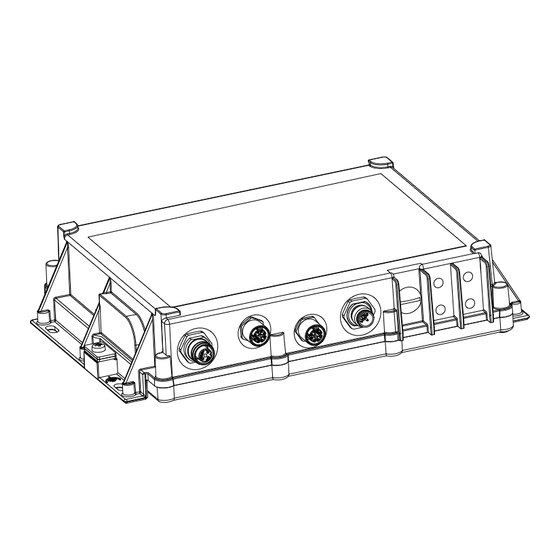
Page 18: Device Views
Supply voltage connection via 5-pin, “A”-coded M12 plug Ethernet port 1 8-pin, “X”-coded M12 socket for 10/100/1000 Mbit/s PoE port Optional: 8-pin, “X”-coded M12 socket for 10/100/1000 Ethernet port 2 Mbit/s twisted pair port V.24/ACA11 4-pin, “A”-coded M12 socket Installation BAT450-F Release 06 08/2017... - Page 19 The reset button below a screwable IP67 protective cap Supply voltage connection via 5-pin, “A”-coded M12 plug Ethernet port 1 8-pin, “X”-coded M12 socket for 10/100/1000 Mbit/s PoE port V.24/ACA11 4-pin, “A”-coded M12 socket SIM 1 SIM 2 Connection for functional ground Installation BAT450-F Release 06 08/2017...
-
Page 20: Power Supply
1000 Mbit/s full duplex Power over Ethernet The socket housing is electrically connected with the device housing. Delivery state: Autonegotiation activated The PoE power is supplied via the wire pairs transmitting the signal (phantom voltage). Installation BAT450-F Release 06 08/2017... -
Page 21: 10/100/1000 Mbit/S Twisted Pair Port
After the supply voltage is set up, the software starts and initializes itself. Afterwards, the device performs a self-test. During this process, various LEDs light up. 1.6.1 Device state These LEDs provide information about conditions which affect the operation of the whole device. Installation BAT450-F Release 06 08/2017... - Page 22 Green Lights up LED lights up after the configuration flashing Device has detected at least one hardware error. green/red Short flashing No password or the default password is set green/red Long flashing Charge lock active Installation BAT450-F Release 06 08/2017...
-
Page 23: Ls/Da
This enables you to set up a connection to the Command Line Interface CLI and to the System Monitor. VT 100 terminal settings Speed 9600 Baud Data 8 bit Stopbit 1 bit Handshake Parity none Installation BAT450-F Release 06 08/2017... - Page 24 ACA11 storage medium. The AutoConfiguration Adapter ACA21-M12 and ACA22-M12 storage media are incompatible with the device. Figure Function Transmit Data Receive Data N.C. Not used Ground Table 4: Pin assignment of the V.24 interface (M12 socket) Installation BAT450-F Release 06 08/2017...
-
Page 25: Reset Button
IP65/67 are only achieved when the protection cap is closed. You will find more information in the “User Manual Configuration Guide”, in the chapter “Using the Boot Configurations”. The “User Manual Configuration Guide” is available as PDF file on the Internet on the Hirschmann product pages (www.hirschmann.com). Installation BAT450-F... -
Page 26: Sim Card Reader (Exclusively For Device Variants With Lte Module)
SIM card slightly deeper into the slot until you hear a click. After you hear a click, release the SIM card. The SIM card pops out of the slot. Place the SIM card in the slot with the contacts face down. Installation BAT450-F Release 06 08/2017... -
Page 27: Installation
Checking the package contents Check whether the package includes all items named in the section “Scope of delivery for device variants featuring Configuration with characteristic value "9"” on page Check the individual parts for transport damage. Installation BAT450-F Release 06 08/2017... -
Page 28: Installing And Grounding The Device
Proceed as follows: Prepare the assembly at the installation site. See “Dimension drawings” on page 45. Install the device with suitable fastening components. Seal all unused connections and ports with protection screws. Installation BAT450-F Release 06 08/2017... -
Page 29: Installing The Device On A Pole
2.2.2 Installing the device on a pole The devices are suitable for pole mounting with the additional BAT450-F pole mounting set (“Scope of delivery, order numbers and accessories”). The BAT450-F pole mounting set with enclosed U-bolts is designed for the following pole diameter range: ... -
Page 30: Grounding The Device
Configuration characteristic value "Z" and available as accessory. See “Scope of delivery, order numbers and accessories” on page 57. You will find information on setting the transmit power in chapter “Configuring the transmit power” on page Installation BAT450-F Release 06 08/2017... -
Page 31: Connecting The Power Supply
You start up the device by connecting the power supply via the 8-pin, “X”- coded M12 socket for PoE port or via a 5-pin, “A”-coded M12 socket. You find the prescribed tightening torque of the locking screw in General technical data section on page 44. Installation BAT450-F Release 06 08/2017... -
Page 32: Connecting Data Cables
Connect the data cables according to your requirements. The tightening torque of the locking screw is 5.3 lb-in (0.6 Nm). For more detail see “Ethernet ports” on page 20 “V.24 interface (external management)” on page 23 Installation BAT450-F Release 06 08/2017... -
Page 33: Defining Ip Parameters
The device offers the following options for assigning the IP parameters: via DHCP (Option 82) via BOOTP via the HiDiscovery or Industrial HiVision application via the V.24 interface via the AutoConfiguration Adapter Installation BAT450-F Release 06 08/2017... -
Page 34: Defining Wlan Basic Settings
(LAN) via the wireless network (WLAN), if the WLAN encryption (e.g. WPA2) is set accordingly in a device with a wireless interface and in the configuration computer. via the V.24 interface Installation BAT450-F Release 06 08/2017... -
Page 35: Set Wwan Basic Settings (Exclusively For Device Variants With Lte Module)
Set WWAN basic settings (exclusively for device variants with LTE module) You will find more information in the “User Manual Configuration Guide”, in the chapter “Configuring WWAN access”. Installation BAT450-F Release 06 08/2017... -
Page 36: Obtain Compliance For Operation In The European Union
Make the country setting unchangeable using the Command Line Interface (CLI), the graphical user interface or the LANconfig software. You can download the LANconfig software as an ISO image from the Hirschmann product pages (www.hirschmann.com). Perform the following work steps: Command Line Interface (CLI) ... - Page 37 Specific country settings such as “France” or “Germany” include additional country specific channels in comparison to the “Europe” country setting. The device ignores specific country settings and uses the country setting “Europe” until the RED compliance has been obtained. Installation BAT450-F Release 06 08/2017...
- Page 38 Note: To check the country setting and correct it, click the “No” button. Then open the Configuration > Wireless LAN > General dialog. To obtain RED compliance, click the “Yes” button. This makes the country setting unchangeable. Subsequently, the device restarts. Installation BAT450-F Release 06 08/2017...
-
Page 39: Configuring The Transmit Power
In the menu tree, open the Configuration > Wireless LAN > General > Physical WLAN settings - Radio dialog. In the “General” tab, click in the “Interface” column the physical WLAN interface to which you connect the antenna. Installation BAT450-F Release 06 08/2017... - Page 40 Subtract the cable and installed overvoltage protector attenuation from the antenna gain. Enter the calculated value in the “Antenna gain” field. Click the “Set” button to save the value. Installation BAT450-F Release 06 08/2017...
-
Page 41: Monitoring The Ambient Air Temperature
It is higher than the ambient air temperature. The maximum internal temperature of the device named in the technical data is a guideline that indicates to you that the maximum ambient air temperature has possibly been exceeded. Installation BAT450-F Release 06 08/2017... -
Page 42: Maintenance And Service
Maintenance and service When designing this device, Hirschmann largely avoided using high-wear parts. The parts subject to wear and tear are dimensioned to last longer than the lifetime of the product when it is operated normally. Operate this device according to the specifications. -
Page 43: 10 Disassembly
10 Disassembly Disconnect the data cables. Disable the supply voltage. Disconnect the power supply cable. Remove the antennas. Disconnect the grounding. Installation BAT450-F Release 06 08/2017... -
Page 44: 11 Technical Data
1060 hPa (−1312 ft; −400 m) Pollution degree Protection classes Laser protection Class 1 in compliance with IEC 60825-1 Degree of protection IP65/67 a. Temperature of the ambient air at a distance of 2 in (5 cm) from the device Installation BAT450-F Release 06 08/2017... -
Page 45: Dimension Drawings
11.2 Dimension drawings inch 10.2 Installation BAT450-F Release 06 08/2017... -
Page 46: Wlan Specifications
In some country profiles, the module automatically reduces the data rate and transmit power downward. This is due to national standards. IEEE 802.11a/b/g/n Data rate Typical transmission power Typical receiving sensitivity 6 Mbit/s 16 dBm −93 dBm Installation BAT450-F Release 06 08/2017... - Page 47 MCS 2 18 dBm −86 dBm MCS 3 18 dBm −82 dBm MCS 4 18 dBm −79 dBm MCS 5 16 dBm −75 dBm MCS 6 16 dBm −73 dBm MCS 7 15 dBm −72 dBm Installation BAT450-F Release 06 08/2017...
- Page 48 MCS 8 20 dBm −92 dBm MCS 9 20 dBm −91 dBm MCS 10 19 dBm −89 dBm MCS 11 20 dBm −84 dBm MCS 12 18 dBm −81 dBm MCS 13 15 dBm −77 dBm Installation BAT450-F Release 06 08/2017...
-
Page 49: Receiver Sensitivity, Transmit Power, And Data Rate Of The Wlan Module Version For High-Gain Antennas (Approvals 2, Characteristic Value H) According To Ieee 802.11A/B/G/N
−84 dBm 48 Mbit/s 7 dBm −80 dBm 54 Mbit/s 6 dBm −79 dBm IEEE 802.11b Data rate Typical transmission Typical receiving sensitivity power 1 Mbit/s 19 dBm −94 dBm 11 Mbit/s 19 dBm −94 dBm Installation BAT450-F Release 06 08/2017... - Page 50 MCS 16 23 dBm −87 dBm MCS 17 23 dBm −90 dBm MCS 18 23 dBm −86 dBm MCS 19 23 dBm −82 dBm MCS 20 16 dBm −79 dBm MCS 21 17 dBm −75 dBm Installation BAT450-F Release 06 08/2017...
- Page 51 MCS 18 8 dBm −89 dBm MCS 19 8 dBm −84 dBm MCS 20 3 dBm −81 dBm MCS 21 2 dBm −77 dBm MCS 22 1 dBm −75 dBm MCS 23 1 dBm −73 dBm Installation BAT450-F Release 06 08/2017...
-
Page 52: Lte Specifications
TX: 880 MHz ... 915 MHz RX: 925 MHz ... 960 MHz DCS 1800: TX: 1710 MHz ... 1785 MHz RX: 1805 MHz ... 1880 MHz Table 6: Technical parameters of the LTE module Installation BAT450-F Release 06 08/2017... -
Page 53: Gnss (Global Navigation Satellite System)
LTE Band 8 −99.3 −98.5 −102.0 −93.3 LTE Band 20 −99.6 −98.4 −99.8 −93.3 Table 8: Conducted RX sensitivity (LTE Bands) a. Per 3GPP specification b. Sensitivity values scale with bandwidth: x_MHz_Sensitivity = 10_MHz_Sensitivity − 10*log(10 MHz/x_MHz) Installation BAT450-F Release 06 08/2017... -
Page 54: Conducted Rx Sensitivity (Umts Bands)
LTE Band 1, 3, 8, 20 +23 dBm ± 1 dB Can vary as per the MPR (Maximum Power Reduction) table in the 3GPP TS_136101 specification LTE Band 7 +22 dBm ± 1 dB Table 11: Conducted TX power tolerances Installation BAT450-F Release 06 08/2017... -
Page 55: Emc
Data line: test level 3 2 kV EN 61000-4-6 Conducted interference voltages, test level 3 150 kHz ... 80 MHz 10 V EMC interference emission EN 55032 Class B FCC 47 CFR Part 15 Class B Installation BAT450-F Release 06 08/2017... -
Page 56: Stability
328 ft (100 m) (for Cat5e cable) 11.8 Power consumption/power output Device power consumption Power output BAT450-F 1 × WLAN module 9.95 W 33.35 Btu (IT)/h 2 × WLAN module 12.95 W 44.19 Btu (IT)/h 1 × WLAN module 11.88 W... -
Page 57: Scope Of Delivery, Order Numbers And Accessories
12 Scope of delivery, order numbers and accessories Installation BAT450-F Release 06 08/2017... - Page 58 Scope of delivery for device variants featuring Configuration with characteristic value "9" Number Article 1 × WLAN module 2 × WLAN module 1 × WLAN module 1 × LTE module 1 × Device 1 × General safety instructions 1 × EU Declaration of Conformity 1 ×, 2 ×...
- Page 59 Scope of delivery for device variants featuring Configuration with characteristic value "Z" Number Article 1 × WLAN module 2 × WLAN module 1 × WLAN module 1 × LTE module 1 × Device 1 × General safety instructions 1 × EU Declaration of Conformity 1 ×, 2 ×...
- Page 60 (10 pcs.) 50-Ω terminating resistors for closing unused antenna connections 942-118-001 (10 pieces) BAT450-F pole mounting set For fastening the devices to pole for the following pole diameter range: 943 966-001 1.46 in ... 2.56 in (37 mm ... 65 mm) Note: Products recommended as accessories may have characteristics that do not fully correspond to those of the corresponding product.
- Page 61 (WWAN-N-O-N-S) 50-Ω terminating resistors for closing unused antenna connections 942-118-001 (10 pieces) BAT450-F pole mounting set For fastening the devices to pole for the following pole diameter range: 943 966-001 1.46 in ... 2.56 in (37 mm ... 65 mm) Note: Products recommended as accessories may have characteristics that do not fully correspond to those of the corresponding product.
-
Page 62: Underlying Technical Standards
– Immunity for industrial environments EN 61131-2 Programmable controllers – Part 2: Equipment requirements and tests FCC 47 CFR Part 15 Code of Federal Regulations IEC/EN 60079-15 Explosive atmospheres – Part 15: Equipment protection by type of protection “n” Installation BAT450-F Release 06 08/2017... - Page 63 Information technology equipment – Safety – Part 1: General requirements The device has an approval based on a specific standard only if the approval indicator appears on the device casing. The device generally fulfills the technical standards named in their current versions. Installation BAT450-F Release 06 08/2017...
-
Page 64: A Further Support
Further support Technical questions For technical questions, please contact any Hirschmann dealer in your area or Hirschmann directly. You find the addresses of our partners on the Internet at http://www.hirschmann.com. A list of local telephone numbers and email addresses for technical support directly from Hirschmann is available at https://hirschmann-support.belden.eu.com. - Page 65 Installation BAT450-F Release 06 08/2017...
Need help?
Do you have a question about the BAT450-F and is the answer not in the manual?
Questions and answers