Table of Contents
Advertisement
User Manual
Installation
Dual-Band Industrial Access Point / Client / Access Bridge
BAT Family
Main 1
Main 2
AUX 1
AUX 2
BAT54-F
Uin : 24 VDC
CLASS 2
Uin : 48 VDC
CLASS 2
IP67 WLAN Access Point
1
+24V DC
1
TX
2
0 V
1
TD+
3
2
RX
2
3
2
1
3
0 V
2
2
RD+
3
N.C.
3
TD-
4
+24V DC
4
GND
4
RD-
3
4
5
N.C.
1
4
1
4
Pin
Function
Pin
Function
5
Pin
Function
V.24
Reset
Ethernet
Power
BAT54-F
Main
AUX
BAT54-F Client
Uin : 24 VDC
CLASS 2
Uin : 48 VDC
CLASS 2
IP67 WLAN Access Point
1
+24V DC
1
TX
2
0 V
1
TD+
3
2
RX
2
3
2
1
3
0 V
2
2
RD+
3
N.C.
3
TD-
4
+24V DC
4
GND
4
RD-
3
4
5
N.C.
1
4
1
4
Pin
Function
Pin
Function
5
Pin
Function
V.24
Reset
Ethernet
Power
BAT54-F Client
M1
WLAN1
WLAN2
BAT54-Rail
Aux1
Aux2
BAT54-Rail
Installation BAT
Release 05 03/2013
Iin : 400 mA
Iin : 170 mA (PoE)
IP67 WLAN Access Point
1
TX
P
LS/DA
3
2
RX
2
3
N.C.
WLAN
WLAN
4
GND
1
4
1
2
Pin
Function
V.24
Reset
LED
BAT54-F Single
Antenna 1
Iin : 420 mA
Iin : 170 mA (PoE)
IP67 WLAN Access Point
1
TX
P
LS/DA
3
2
RX
2
3
N.C.
WLAN
NC
4
GND
1
4
Pin
Function
V.24
Reset
LED
BAT300-F
Main
Aux
ETH
P
WLAN
+24V
0V
+24V
0V
x
BAT54-Rail Single
Reset
V.24
12V DC
BAT54-Rail Single
Main
AUX
BAT54-F Single
Uin : 24 VDC
CLASS 2
Iin : 420 mA
Uin : 48 VDC
CLASS 2
Iin : 170 mA (PoE)
1
TD+
1
TD+
LS/DA
P
2
3
2
RD+
2
3
2
RD+
2
3
TD-
3
TD-
4
RD-
LS/DA
4
RD-
WLAN
1
4
1
4
Pin
Function
Pin
Function
1
Ethernet 2
Ethernet 1
LED
Antenna 2
Antenna 3
BAT300-F
Uin : 24 VDC
CLASS 2
Iin : 420 mA
Uin : 48 VDC
CLASS 2
Iin : 170 mA (PoE)
1
+24V DC
2
0 V
1
TD+
P
LS/DA
2
3
2
1
3
0 V
2
RD+
3
TD-
4
+24V DC
4
RD-
3
4
5
N.C.
NC
WLAN
1
4
Pin
Function
5
Pin
Function
Ethernet
Power
LED
Main
Aux
BAT54-Rail Client
BAT54-Rail Client
https://hirschmann-support.belden.eu.com
BAT300-Rail
BAT300-Rail
Technical support
Advertisement
Table of Contents

Related Manuals for Hirschmann BAT series


Summary of Contents for Hirschmann BAT series
- Page 1 V.24 Reset Ethernet Power BAT54-F Client BAT300-F Main Main WLAN +24V WLAN1 WLAN2 +24V BAT54-Rail BAT54-Rail Client BAT54-Rail Single BAT300-Rail Reset V.24 12V DC Aux1 Aux2 BAT54-Rail BAT54-Rail Single BAT54-Rail Client BAT300-Rail Installation BAT Technical support Release 05 03/2013 https://hirschmann-support.belden.eu.com...
- Page 2 In addition, we refer to the conditions of use specified in the license contract. You can get the latest version of this manual on the Internet at the Hirschmann product site (www.hirschmann.com). Printed in Germany Hirschmann Automation and Control GmbH Stuttgarter Str.
-
Page 3: Table Of Contents
Contents Safety instructions About this manual Device description Properties and functions 1.1.1 BAT-F types 1.1.2 BAT-Rail types 1.1.3 BAT54 types 1.1.4 BAT300 types 1.1.5 BAT-BG/BGN types 1.1.6 Other features Interfaces and control elements 1.2.1 BAT54-F 1.2.2 BAT54-F Single 1.2.3 BAT54-F Client 1.2.4 BAT300-F 1.2.5 BAT54-Rail 1.2.6 BAT54-Rail Single... - Page 4 2.7.2 BAT-Rail Mounting/connecting external antennas 2.8.1 Connections for external antennas on BAT-F 2.8.2 Connections for external antennas on BAT-Rail 2.8.3 Mounting external antennas Connecting LAN and WLAN connectors 2.9.1 BAT-F 2.9.2 BAT-Rail 2.10 Grounding 2.10.1 BAT-F 2.10.2 BAT-Rail 2.11 Connecting the supply voltage 2.11.1 5-pin M12 connector (BAT-F) 2.11.2 4-pin terminal block (BAT-Rail) 2.11.3 Power over Ethernet (PoE) -...
-
Page 5: Safety Instructions
Safety instructions Certified usage Only use the device for application cases that are described in the Hirschmann product information, including this manual. Only operate the device according to the technical specifications. Supply voltage The devices are designed for operation with a safety extra-low voltage. - Page 6 BAT-F types: A separate screw connector on the housing is provided for the functional ground (FE). This is indicated by the functional ground symbol ( ). The functional ground is electrically connected to the switching ground and the metal housing of the device. BAT-Rail types: The lower panel of the device housing is grounded by means of the DIN rail.
- Page 7 Operate the device at the specified surrounding air temperature (temperature of the surrounding air at a distance of up to 1.97 in (5 cm) from the device) and relative air humidity specified in the technical data. When you are selecting the installation location, make sure you observe the climatic threshold values specified in the technical data.
- Page 8 When operating the BAT54/300-Rail types in Ex zone 2, the following applies: II 3G Ex nA IIC T4 Gc, -30 °C ... +50 °C DEKRA 11ATEX0007 X Temperature Code T4 Ambient -30 °C … +50 °C List of Standards EN 60079-0: 2009 EN 60079-15: 2010 DO NOT OPEN WHEN ENERGIZED.
- Page 9 Lightning protection When you mount devices and / or antennas outdoors, there is a risk of them being struck by lightning. Additionally, there is the risk of voltage surges being transmitted into the interior of the building. It is your responsibility to take appropriate measures to mitigate the effects of lightning strikes.
- Page 10 Non-observance of these safety instructions can cause material damage and/or injuries. Only appropriately qualified personnel should work on this device or in its vicinity. The personnel must be thoroughly familiar with all the warnings and maintenance procedures outlined in this operating manual.
- Page 11 Supply the voltage to the device via a Power-over-Ethernet (PoE) switch or via a power unit that conforms to IEEE 802.3af. You will find information on Hirschmann PoE-capable switches under http://www.hirschmann.com. Install an upstream filter on the 24V DC voltage supply. You will find information on suitable filters under http://www.hirschmann.com.
- Page 12 MiMo5-9N-IP65 in the 5.15 - 5.25 GHz band is only permitted with an attenuation of 3dB between antenna ports of the main unit and antenna. Attenuation may be realized by a low loss cable such as Hirschmann BAT-CLB-2N m-f (Order Number: 943 903-514).
- Page 13 This Class B digital apparatus complies with Canadian ICES-003. Cet appareil numérique de la classe B est conforme à la norme NMB-003 du Canada. To reduce potential radio interference to other users, the antenna type and its gain should be so chosen that the equivalent isotropically radiated power (EIRP) is not more than that permitted for successful communication.
-
Page 14: About This Manual
About this manual The “Installation” user manual contains a device description, safety instructions, a description of the display, and the other information that you need to install the device. The following manuals are available as PDF files on the CD/DVD supplied: ... -
Page 15: Device Description
Device description Properties and functions The devices allow you to set up WLANs (Wireless Local Area Networks) in a local network. In contrast to a conventional network connection via copper cables and glass fibers, some of the communication is performed by means of a radio link. -
Page 16: Bat-F Types
The devices differ with regard to their design, the standards they support and their certifications, as shown in the table below: Design Indoor Outdoor BAT-Rail types BAT-F types Ex range BAT X2 types BAT54-Rail BAT54-F BAT54-F X2 BAT54-Rail-Client BAT54-F Single BAT54-F Single X2 BAT54-Rail Single BAT54-F Client... -
Page 17: Bat300 Types
2.4 GHz. Hirschmann supports you by providing country profiles. These profiles help you to conform to the requirements of the country in which you are operating the WLAN installation. -
Page 18: Other Features
1.1.6 Other features Features can be managed via a Web browser, via Telnet, with a management software product (such as Industrial HiVision or LANconfig/LANmonitor) or locally on the device (V.24 interface). The devices provide high mobility combined with maximum security. The devices provide you with a large range of features: ... - Page 19 Cross-platform WLAN management A standardized, cross-platform management system for transparent and efficient network monitoring (SNMP) Windows management suite: LANconfig, LANmonitor, WLANmonitor Direct management via Web browser (HTTP, HTTPS) Command line level: TelNet Can always be reached via serial interface ...
-
Page 20: Interfaces And Control Elements
Interfaces and control elements 1.2.1 BAT54-F The device is equipped with the following connectors and operation elements: Main 1 Main 2 AUX 1 AUX 2 BAT54-F Uin : 24 VDC CLASS 2 Iin : 400 mA Uin : 48 VDC CLASS 2 Iin : 170 mA (PoE) IP67 WLAN Access Point... -
Page 21: Bat54-F Single
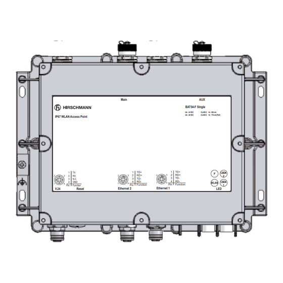
1.2.2 BAT54-F Single The device is equipped with the following connectors and operation elements: Main BAT54-F Single Uin : 24 VDC CLASS 2 Iin : 420 mA Uin : 48 VDC CLASS 2 Iin : 170 mA (PoE) IP67 WLAN Access Point LS/DA N.C. -
Page 22: Bat54-F Client
1.2.3 BAT54-F Client The device is equipped with the following connectors and operation elements: Main BAT54-F Client Uin : 24 VDC CLASS 2 Iin : 420 mA Uin : 48 VDC CLASS 2 Iin : 170 mA (PoE) IP67 WLAN Access Point +24V DC LS/DA N.C. -
Page 23: Bat300-F
1.2.4 BAT300-F The device is equipped with the following connectors and operation elements: Antenna 2 Antenna 1 Antenna 3 BAT300-F Uin : 24 VDC CLASS 2 Iin : 420 mA Uin : 48 VDC CLASS 2 Iin : 170 mA (PoE) IP67 WLAN Access Point +24V DC LS/DA... -
Page 24: Bat54-Rail
1.2.5 BAT54-Rail The device is equipped with the following connectors and operation elements: Main 1 Main 2 WLAN1 WLAN2 BAT54-Rail Aux1 Aux2 Interfaces and display and control elements ETH1 First Ethernet port 10/100BASE-TX, Autosensing, Power over Ethernet (PoE), automatic MDI/MDIX recognition (no crossover cable required) +24V Power, power supply connector for safety extra-low voltage (SELV/PELV) 12V DC... -
Page 25: Bat54-Rail Single
1.2.6 BAT54-Rail Single The device is equipped with the following connectors and operation elements: Main WLAN +24V +24V BAT54-Rail Single Reset V.24 12V DC Interfaces and display and control elements Ethernet port: 10/100BASE-TX, Autosensing, Power over Ethernet (PoE), automatic MDI/MDIX recognition (no crossover cable required) +24V Power, power supply connector for safety extra-low voltage (SELV/PELV) 12V DC... -
Page 26: Bat54-Rail Client
1.2.7 BAT54-Rail Client The device is equipped with the following connectors and operation elements: Main BAT54-Rail Client Interfaces and display and control elements Ethernet port: 10/100BASE-TX, Autosensing, Power over Ethernet (PoE), automatic MDI/MDIX recognition (no crossover cable required) +24V Power, power supply connector for safety extra-low voltage (SELV/PELV) 12V DC Power, power supply connector for safety extra-low voltage (SELV/PELV) V.24... -
Page 27: Bat300-Rail
1.2.8 BAT300-Rail The device is equipped with the following connectors and operation elements: BAT300-Rail Interfaces and display and control elements ETH1 First Ethernet port 10/100BASE-TX, Autosensing, Power over Ethernet (PoE), automatic MDI/MDIX recognition (no crossover cable required) +24V Power, power supply connector for safety extra-low voltage (SELV/PELV) 12V DC Power, power supply connector for safety extra-low voltage (SELV/PELV) V.24... -
Page 28: Device Models
Device models 1.3.1 BAT54-F devices Device Area of application BAT54-F FCC Outdoors, also hazardous environments BAT54-F Outdoors, also hazardous environments BAT54-F X2 FCC Outdoors, also under extreme conditions, including environments with the danger of explosions BAT54-F X2 Outdoors, also under extreme conditions, including environments with the danger of explosions BAT54-F Client Outdoors, also hazardous environments... -
Page 29: Bat54-Rail Devices
1.3.2 BAT54-Rail devices Device Area of application BAT54-Rail DIN rail and flat surface mounting BAT54-Rail - FCC DIN rail and flat surface mounting BAT54-Rail - Japan DIN rail and flat surface mounting BAT54-Rail Client DIN rail and flat surface mounting BAT54-Rail Client (FCC) DIN rail and flat surface mounting BAT54-Rail Single DIN rail and flat surface mounting... -
Page 30: Bat-Bg/Bgn Devices
1.3.5 BAT-BG/BGN devices Device Area of application BAT300-Rail BGN Using the 2.4 GHz ISM wave band DIN rail and flat surface mounting Higher radio output and more stable network coverage through MIMO with 3 antennas BAT300-F BGN Using the 2.4 GHz ISM wave band Higher radio output and more stable network coverage through MIMO with 3 antennas BAT54-F Client BG... -
Page 31: Assembly And Start-Up
Assembly and start-up Installing the device The devices have been developed for practical application in a harsh industrial environment. On delivery, the device is ready for operation. The following procedure has been proven to be successful for the assembly of the device: ... -
Page 32: Putting Components Together (Bat-F)
Putting components together (BAT-F) To protect the exposed contacts of the components from dirt, the individual system components must be connected in a dry and clean area. Seal unused ports with the cover caps supplied. Note: Connectors are not electrical isolating devices. Therefore, first plug the connector into the power supply plug, then switch on the power supply. - Page 33 When implementing your lightening protection concept, make sure you meet the requirements of standards VDE 0182 and IEC 62305. Hirschmann recommends using the Hirschmann BAT Protector as a lightening protection (see on page 67 “Accessories”).
-
Page 34: Pole Mounting
2.5.2 Pole mounting The BAT-F devices are suitable for pole mounting with the additional BAT-F pole mounting set (see on page 67 “Accessories”). The BAT-F pole mounting set is designed for: Pole diameter: 37 mm to 60 mm (1.46 in to 2.36 in) ... -
Page 35: Din Rail Mounting (Bat-Rail)
DIN rail mounting (BAT-Rail) Mount the device on a 35 mm DIN rail in accordance with DIN EN 60175. Attach the upper snap-in guide of the device into the DIN rail and press the device down against the DIN rail until it snaps into place. Note: The shielding ground of the industrial connectable twisted pair lines is connected to the lower panel as a conductor. -
Page 36: Bat-Rail
2.7.2 BAT-Rail a i l Figure 7: BAT-Rail, wall mounting Fasten on the wall mounting plate (width 120 mm / 4.73 in) (see on page 67 “Accessories”) on a level wall surface using four screws. Mount the device on the wall plate as shown in the illustration. Attach the upper snap-in guide of the device into the rail and press it down against the rail until it snaps into place. - Page 37 BAT54-F AUX 1 Main 1 Main 2 AUX 2 BAT54-F Uin : 24 VDC CLASS 2 Iin : 400 mA Uin : 48 VDC CLASS 2 Iin : 170 mA (PoE) IP67 WLAN Access Point +24V DC LS/DA N.C. +24V DC WLAN WLAN...
- Page 38 BAT54-F Client Main BAT54-F Client Uin : 24 VDC CLASS 2 Iin : 420 mA Uin : 48 VDC CLASS 2 Iin : 170 mA (PoE) IP67 WLAN Access Point +24V DC LS/DA N.C. +24V DC N.C. WLAN Function Function Function V.24...
-
Page 39: Connections For External Antennas On Bat-Rail
2.8.2 Connections for external antennas on BAT-Rail BAT54-Rail The devices have four Reverse satellite master antenna (SMA) connectors for connecting external antennas. WLAN1 WLAN2 BAT54-Rail Aux1 Aux2 Figure 12: Connections for external antennas on BAT54-Rail 1 - Antenna 1 2 - Antenna 2 3 - Aux1 4 - Aux2... - Page 40 BAT54-Rail Client The devices have two Reverse SMA connectors for connecting external antennas. Main BAT54-Rail Client Figure 14: Connections for external antennas on BAT54-Rail Client 1 - Main 2 - Aux BAT300-Rail The devices have three Reverse SMA connectors for connecting external antennas.
-
Page 41: Mounting External Antennas
2.8.3 Mounting external antennas Connect the external antenna to the corresponding ‘Antenna Main’ connection. If you only want to connect one antenna with only one connection for each radio module, you use the main connection. BAT54 types: Use the respective main connection of the two WLAN modules to connect antennas that have only one antenna connection without diversity. -
Page 42: Connecting Lan And Wlan Connectors
Connecting LAN and WLAN connectors In the “Dual-Band Industrial Access Point / Client / Access Bridge BAT54- Rail” user manual, you will find further information for connecting the LAN and WLAN connections with the corresponding remote terminals. 2.9.1 BAT-F Connect the access point to your LAN for configuration. ... -
Page 43: Grounding
2.10 Grounding 2.10.1 BAT-F A separate anti-torsion screw connector on the housing is provided for the functional ground (FE) . It is indicated by the functional ground symbol ( The functional ground is electrically connected to the switching ground and to the metal housing of the device. -
Page 44: Connecting The Supply Voltage
2.11 Connecting the supply voltage For redundant and outfall-resistant power, you can connect multiple power sources in any combination at the same time. The device automatically selects the power supply. Note: Switch over to a redundant power supply may not be seamless. If the power supply currently active is interrupted and another power supply takes over, the device may reboot to activate the redundant power supply. -
Page 45: Power Over Ethernet (Poe) - Power Supply Via The Lan Cable
Note: Relevant for BAT-Rail types: The tightening torque for field wiring terminals is 2 - 4 lb in. (0.22 - 0.25 Nm). Figure Function + 24 V DC + 24 V DC Table 5: Pin assignment of the 4-pin terminal block on the BAT-Rail 2.11.3 Power over Ethernet (PoE) - power supply via the LAN cable... -
Page 46: Connecting The Data Lines
2.12 Connecting the data lines 2.12.1 10/100 Mbit/s twisted pair connection In the BAT-F, the 10/100 Mbit/s twisted pair connections are M12 sockets. 10/100 Mbit/s ports enable the connection of terminal devices or independent network segments according to the IEEE 802.3 100BASE-TX / 10BASE-T standard. - Page 47 The patch cables for operating the device are shown in table Patch cables Wire pairs M12 4-pin on M12 4-pin, crossed 1 (TX+) – 2 (RX+) (MDI to MDI) 2 (RX+) – 1 (TX+) 3 (TX−) – 4 (RX−) 4 (RX−) – 3 (TX−) M12 4-pin on M12 4-pin, 1:1 1 (TX+) –...
-
Page 48: 10/100 Mbit/S Twisted Pair Connection
2.12.2 10/100 Mbit/s twisted pair connection In the BAT-Rail, the 10/100 Mbit/s twisted pair connections are RJ45 sockets. 10/100 Mbit/s ports enable the connection of terminal devices or independent network segments according to the IEEE 802.3 100BASE-TX / 10BASE-T standard. These ports support: ... -
Page 49: Mounting The Housing Cover For Bat-F X2
2.13 Mounting the housing cover for BAT-F X2 For use in environments with the danger of explosions, the BAT-F X2 device models have an additional housing cover made of stainless sheet steel. On delivery, the housing cover is pre-mounted. Perform the installation in the following steps: ... -
Page 50: Startup Procedure
2.14 Startup procedure 2.14.1 BAT-F Connecting the voltage supply via the 5-pin M12 connector or via the LAN cable (Power over Ethernet) starts the operation of the device. 2.14.2 BAT-Rail Connecting the voltage supply via the terminal block Pull the terminal block off the device and connect the voltage supply lines. - Page 51 You require external antennas for operating the devices. You can find information on the connectable antennas on the Internet under http://www.hirschmann.com. When installing external antennas, make sure that you adhere to the regulations of the country in which you are operating the WLAN device, and to the general operating permission and the maximum emission levels.
- Page 52 Open the configuration for the physical interface to which you are connecting the antenna. On the Radio tab you will find an entry field for the antenna gain (see the following figure): Installation BAT Release 05 03/2013...
- Page 53 Subtract the cable attenuation and any losses due to over voltage protector installed devices from the antenna gain, and enter the result in dB in the antenna gain field. Installation BAT Release 05 03/2013...
- Page 54 2.17 Display elements After the operating voltage is applied, the software starts and initializes itself. The device then performs a self-test. During this process, the LEDs light up. The process takes a number of seconds. BAT54-F BAT54-F Single LS/DA LS/DA WLAN WLAN LS/DA...
- Page 55 Main WLAN2 WLAN1 BAT54-Rail BAT54-Rail Single BAT54-Rail BAT54-Rail Single Main BAT300-Rail BAT54-Rail Client BAT54-Rail Client BAT300-Rail Figure 19: Display elements for BAT54-Rail, BAT54-Rail Client, BAT300-Rail 1 - Ethernet port link status (LS) 2 - Ethernet port data (DA) 3 - Power (P) 4 - WLAN1 5 - WLAN2 6 - M1...
- Page 56 Meaning of the LEDs The following terms describe the behavior of the LEDs: Blinking: the LED switches on and off at regular intervals. Flashing: the LED lights up very briefly, then is switched off for a much longer time (about 10x as long).
- Page 57 2.18 Operation element (reset button) With these devices, the operating elements include a reset button. 2.18.1 Functions The reset button has two different functions, which are triggered by pressing the button for different lengths of time: Resetting the configuration (hard reset) – the button is pressed for more than 5 seconds but less than 10 seconds.
- Page 58 ACA 11. This enables you to set up a connection to the Command Line Interface (CLI) and to the system monitor. Caution! Available as an accessory for certain Hirschmann devices, the AutoConfiguration Adapter ACA21-M12 is not designed to be used with BAT-F devices.
- Page 59 VT 100 terminal settings Data 8 bit Stopbit 1 bit Handshake Parity none The connector is a 4-pin M12 female connector with A coding. On delivery, the connector is sealed with a cover cap. The housing of the M12 socket and the signal connectors are electrically connected to the functional ground (FE) ( ) and to the metal housing of the device.
- Page 60 2.21 Maintenance and service When designing this device, Hirschmann was largely able to forego using parts that are subject to wear and tear. The parts subject to wear are designed to last longer than the lifetime of the product when it is operated properly.
- Page 61 2.22 Disassembly To remove the device from the DIN rail, press the device downwards and pull it out from under the DIN rail. Figure 21: Removal from the DIN rail Installation BAT Release 05 03/2013...
-
Page 62: Technical Data
Technical data General technical data Description BAT54 types Dual-band industrial WLAN access point/client in accordance with IEEE 802.11a/b/g/h and IEEE 802.11i BAT300 types Dual-band industrial high-performance WLAN access point/client in accordance with IEEE 802.11a/b/g/h and 802.11n BAT-Rail types Used on DIN rail, 5-way (4-way for BAT-Client types) redundant voltage supply, vibration-resistant metal housing BAT-F types Mounted on pole or flat surface (wall), protection class IP67,... - Page 63 Insulation voltage 800 V DC between operating Protective elements limit the insulation voltage to voltage connectors 45 V DC. and housing Environment Storage temperature -30 °C to +70 °C ( -22 °F to +158 °F) (ambient air temperature) Humidity 10% to 95% (non-condensing) Atmospheric pressure up to 2,000 m (795 hPa) Operating...
- Page 64 Roaming BAT... Seamless handover, IAPP support, IEEE 802.11d support, background scanning for rogue AP detection and fast roaming Transmission BAT54 2.4 GHz 802.11b: +19 dBm @1 and 2 Mbit/s, +19 dBm @ power (except for 5.5 and 11 Mbit/s, 2.4 GHz 802.11g: +19 dBm @ 6 Mbit/s, BG/BGN types) +14 dBm @ 54 Mbit/s, 5 GHz 802.11a/h:+18 dBm @ 6 Mbit/s, +12 dBm @ 54...
- Page 65 EMC interference immunity EN 61000-4-2 Electrostatic discharge Contact discharge: test level 3 6 kV Air discharge: test level 3 8 kV EN 61000-4-3 Electromagnetic field, test level 3 - 80 - 2000 MHz 10 V/m - 2000 MHz - 2700 MHz 3 V/m EN 61000-4-4 Fast transients (burst), test level 3...
- Page 66 Network range TP port Length of a twisted pair segment max. 100 m/328 ft (for cat5e cable) Table 12: TP port 10BASE-T / 100BASE-TX / 1000BASE-T Power consumption/power output and order numbers Device Power Power output Order number consumption BAT54-F 10.0 W...
- Page 67 Scope of delivery Device Scope of delivery Device Installation user manual in German and English CD/DVD with following content: - Management software LANconfig - Monitoring software LANmonitor and WLANmonitor - Installation user manual in PDF format in German/English - User manual in PDF format in German/English - Reference manual in PDF format in German/English - HiLCOS operating system as upx file 50 Ohm connection...
- Page 68 The device has a certification based on a specific standard only if the certification indicator appears on the housing. However, with the exception of Germanischer Lloyd, ship certifications are only included in the product information under www.hirschmann.com. Installation BAT Release 05 03/2013...
-
Page 69: A Further Support
Further Support Technical Questions For technical questions, please contact any Hirschmann dealer in your area or Hirschmann directly. You will find the addresses of our partners on the Internet at http://www.hirschmann.com Contact our support at https://hirschmann-support.belden.eu.com You can contact us in the EMEA region at ...
Need help?
Do you have a question about the BAT series and is the answer not in the manual?
Questions and answers