
Subscribe to Our Youtube Channel
Related Manuals for Hirschmann BAT-R


Summary of Contents for Hirschmann BAT-R
-
Page 1: User Manual
User Manual Installation Open Dual-Band Industrial Access-Point / Client / Access- Bridge OpenBAT-Family: BAT-R Installation BAT-R Technical Support Release 09 03/2017 https://hirschmann-support.belden.eu.com... - Page 2 In addition, we refer to the conditions of use specified in the license contract. You can get the latest version of this manual on the Internet at the Hirschmann product site (www.hirschmann.com). Hirschmann Automation and Control GmbH Stuttgarter Str.
-
Page 3: Table Of Contents
Checking the package contents Installing and grounding the device 2.2.1 Installing the device onto the DIN rail 2.2.2 Mounting on a vertical flat surface 2.2.3 Grounding the device Installing an SFP transceiver (optional) Installing the antennas Installation BAT-R Release 09 03/2017... - Page 4 Receive sensitivity, transmission power and data rate according to IEEE 802.11a/b/g/n Receiver sensitivity, transmit power, and data rate of the WLAN module version for high-gain antennas (approvals 2, characteristic value H) according to IEEE 802.11a/b/g/n EMC and immunity Installation BAT-R Release 09 03/2017...
- Page 5 Network range Power consumption/power output Scope of delivery, order numbers and accessories Underlying technical standards Further support Installation BAT-R Release 09 03/2017...
-
Page 6: Safety Instructions
Certified usage Use the product only for the application cases described in the Hirschmann product information, including this manual. Operate the product only according to the technical specifications. See “Technical data” on page 52. Connect to the product only components suitable for the requirements of the specific application case. - Page 7 This is the prerequisite for grounding and labeling circuits, devices, and systems in accordance with current standards in safety technology. Qualified personnel are aware of the dangers that exist in their work. Installation BAT-R Release 09 03/2017...
- Page 8 Relevant for North America: The power cords are suitable for ambient air temperatures of at least 167 °F (75 °C). The power cord wires are made of copper. Table 1: Requirements for connecting electrical wires Installation BAT-R Release 09 03/2017...
- Page 9 The wire diameter of the power supply cable is at least 0.75 mm² (North America: AWG18) on the supply voltage input. Table 2: Requirements for connecting the supply voltage Enable the supply voltage for the device only when the following requirements are fulfilled: Installation BAT-R Release 09 03/2017...
- Page 10 In Ex zone 2, only devices with a corresponding label may be operated. When operating the BAT-R types with characteristic value G for approvals 1 (ATEX zone 2), the following applies: Never use the supply voltage with characteristic value K in Ex zone 2.
- Page 11 In Ex zone 2, only the devices with a corresponding label may be operated in explosion hazard areas Class I, Division 2. When operating the BAT-R types in explosion hazard areas Class I, Division 2, the following applies: Class I, Div. 2 Goups A, B, C and D Temperature code T4 Ambient: −40 °F ...
- Page 12 Installation BAT-R Release 09 03/2017...
- Page 13 Installation BAT-R Release 09 03/2017...
- Page 14 In accordance with the above-named EU directive(s), the EU conformity declaration will be available to the relevant authorities at the following address: Hirschmann Automation and Control GmbH Stuttgarter Str. 45-51 72654 Neckartenzlingen Germany The product can be used in living areas (living area, place of business, small business) and in industrial areas.
- Page 15 This equipment generates, uses and can radiate radio frequency energy and, if not installed and used in accordance with the instructions, may cause harmful interference to radio Installation BAT-R Release 09 03/2017...
- Page 16 Note for the use in the USA and in Canada The following section applies to BAT-R variants with the characteristic value US (USA/Canada) for country approvals which are labeled as...
- Page 17 Note for the use in the USA and in Canada The following section applies to BAT-R variants with the characteristic value US (USA/Canada) for country approvals which are labeled as follows:...
-
Page 18: Ghz Band
Connect the BAT-ANT-N-MiMo-18N-IP65 in this way exclusively. Differing connection configurations are illegal. Note for the use in the Japan This note applies to BAT-R variants with the characteristic value JP (Japan) for country approvals that are labeled as follows: "Contains MIC ID: 204-310014"... - Page 19 The use of antennas missing in this list is prohibited. The 5 GHz band is restricted to indoor usage. Recycling note After usage, this device must be disposed of properly as electronic waste, in accordance with the current disposal regulations of your county, state, and country. Installation BAT-R Release 09 03/2017...
-
Page 20: About This Manual
About this manual The “Installation” user manual contains a device description, safety instructions, a description of the display, and the other information that you need to install the device. Installation BAT-R Release 09 03/2017... -
Page 21: Key
The symbols used in this manual have the following meanings: Listing Work step Subheading Installation BAT-R Release 09 03/2017... -
Page 22: Description
Temperature range Approvals The BAT-R devices are designed for the special requirements of industrial automation. They meet the relevant industry standards, provide very high operational reliability, even under extreme conditions, and also long-term reliability and flexibility. The devices work without a fan. -
Page 23: Device Name And Product Code
The devices provide you with a large range of functions, which the manuals for the operating software inform you about. You can download these manuals as PDF files from the Internet on the Hirschmann product pages (www.hirschmann.com). The Industrial HiVision Network Management software provides you with additional options for smooth configuration and monitoring: ... - Page 24 Class I, Division 2 Groups A, B, C, D Hazardous Locations ATEX Zone 2 Substation applications (EN 61850) Rail applications (EN 50155) Motor vehicles applications (E type- approval mark, ECE No. 10) No additional approvals Table 3: Device name and product code Installation BAT-R Release 09 03/2017...
- Page 25 Hirschmann standard Device model Hirschmann standard Table 3: Device name and product code a. The power supply for this type is only via the LAN as a Powered Device according to the technical standard IEEE 802.3af. Installation BAT-R Release 09 03/2017...
- Page 26 - The operator knows of the access possibilities, regardless of whether they need a tool. c. Location outside the operator area to which the service personnel has access, even when the device is switched on. Installation BAT-R Release 09 03/2017...
-
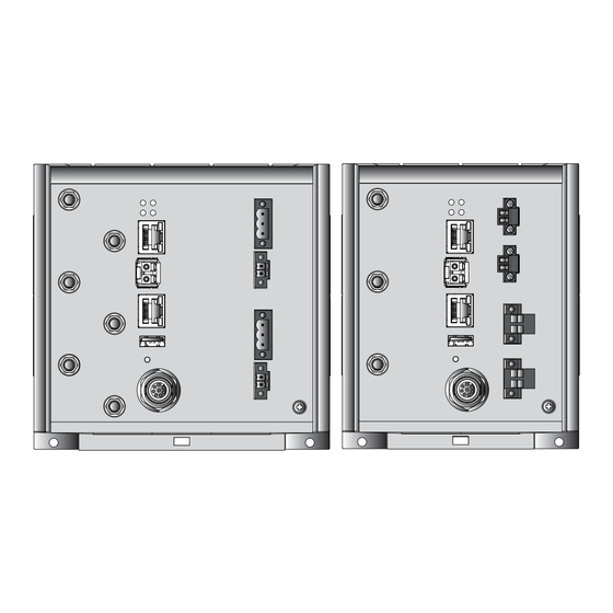
Page 27: Device View
Supply voltage with the characteristic value C and K: RJ45 socket for 10/100/1000 Mbit/s Twisted Pair connections Supply voltage with the characteristic value P and W: RJ45 socket for 10/100/1000 Mbit/s PoE PD port SFP slot for 1000 Mbit/s F/O port Installation BAT-R Release 09 03/2017... -
Page 28: Power Supply
Switching to a redundant voltage source possibly occurs with a short delay. If the active power source is lost and another power source takes over the power supply to the device, the device reboots if necessary to activate the redundant power supply. Installation BAT-R Release 09 03/2017... -
Page 29: Supply Voltage With The Characteristic Value C
PoE PD port serves as the PoE power supply voltage. The PoE power supply means that no separate power supply is required for your device. For further information see “10/100/1000 Mbit/s PoE PD port” on page Installation BAT-R Release 09 03/2017... -
Page 30: Ethernet Ports
Autocrossing (if autonegotiation is activated) Autonegotiation Autopolarity 10 Mbit/s half-duplex mode, 10 Mbit/s full duplex mode 100 Mbit/s half-duplex mode, 100 Mbit/s full duplex mode 1000 Mbit/s full duplex Installation BAT-R Release 09 03/2017... -
Page 31: 10/100/1000 Mbit/S Twisted-Pair Connection (Optional)
Positive V TX− BI_DA− Positive V — BI_DC+ Negative V — BI_DC− Negative V a. Phantom supply b. Spare pair supply M12 4-pin (“D”-coded) Data Positive V Negative V TX− Positive V RX− Negative V Installation BAT-R Release 09 03/2017... - Page 32 M12 8-pin (“X”-coded) 10/100 Mbit/s 1000 Mbit/s BI_DB+ Negative V RX− BI_DB− Negative V BI_DA+ Positive V TX− BI_DA− Positive V — BI_DC+ — — BI_DC− — — BI_DD− — — BI_DD+ — Installation BAT-R Release 09 03/2017...
-
Page 33: Connections For Antennas
Version A) on each WLAN module. The "Antenna Guide" document provides an overview of the antennas that can be used as well as the suitable antenna accessories. This document is available for download as a PDF file on the Hirschmann product pages (www.hirschmann.com). Display elements After the supply voltage is set up, the software starts and initializes itself. -
Page 34: Port Status
Hardware error detected in the WLAN module. 1.7.3 Port status These LEDs display port-related information. The LEDs are directly located on the ports. LS/DA (green/yellow LED) Meaning No network device connected green glowing Ethernet connection active yellow flickering Data traffic Installation BAT-R Release 09 03/2017... -
Page 35: Management Interfaces
You will find more information here: – table 5 on page 36 BAT-R device. Connecting the BAT-R device allows you to automate the configuration of a point-to-point WLAN line by connecting two devices directly via the serial interface. You will find more information here: –... -
Page 36: Usb Interface
AutoConfiguration Adapter ACA21-M12. This storage medium is used for saving/loading the configuration and diagnostic functions, and for loading the software. The USB interface has the following properties: Supports the USB master mode Supports USB 1.1 (data rate max. 12 MBit/s) Installation BAT-R Release 09 03/2017... -
Page 37: Signal Contact
You have the option of setting the signal contact manually using the device management. 1.10 Reset button The device has a reset button. You will find more information in the “User Manual Configuration Guide”, in the chapter “Using the Boot Configurations”. Installation BAT-R Release 09 03/2017... -
Page 38: Installation
Making basic settings Configuring the transmit power Checking the package contents Check whether the package includes all items named in the section “Scope of delivery” on page Check the individual parts for transport damage. Installation BAT-R Release 09 03/2017... -
Page 39: Installing And Grounding The Device
Slide the upper snap-in guide of the device into the DIN rail. Pull the rail lock slide down using a screwdriver, and press the lower part of the device against the DIN rail. Snap in the device by releasing the rail lock slide. Installation BAT-R Release 09 03/2017... -
Page 40: Mounting On A Vertical Flat Surface
If needed remove a section of the overlay material to ensure a reliable main protective earthing connection. Installing an SFP transceiver (optional) Use only Hirschmann SFP transceivers which are suitable for usage with the device. See “Accessories” on page 65. -
Page 41: Installing The Antennas
Table 8: Antenna connections If you connect to 2 BAT-R devices antennas to 2 WLAN modules, ensure that there is a distance of at least 2 m between the BAT-R devices. If you would like to connect several antennas to a WLAN module, align the antennas so that the points of the antennas point away form each other in a star shape. -
Page 42: Connecting The Terminal Blocks (Optional)
Minus terminal of the supply Voltage range DC incl. voltage maximum tolerances 18 V ... 60 V Table 9: Supply voltage with the characteristic value C: type and specification of the supply voltage, pin assignment on the device Installation BAT-R Release 09 03/2017... -
Page 43: Supply Voltage With The Characteristic Value K
Voltage range AC incl. Protective conductor maximum tolerances 88 V ... 265 V, 47 Hz ... 63 Hz Table 10: Supply voltage with the characteristic value K: type and specification of the supply voltage, connections Installation BAT-R Release 09 03/2017... -
Page 44: Supply Voltage With The Characteristic Value W
Connect the wires according to the pin assignment on the device with the clamps. Fasten the wires connected by tightening the terminal screws. 2.5.4 Signal contact Device variants featuring supply voltage with the characteristic value C, K or W have a signal contact exclusively. Installation BAT-R Release 09 03/2017... -
Page 45: Operating The Device
Note: For devices with 2 WLAN modules, the option of suppling power via PoE is unavailable. NOTICE MATERIAL DAMAGE In a PoE installation, use only devices that comply with the IEEE 802.3af/at standard. Non-adherence to these instructions can lead to equipment damage. Installation BAT-R Release 09 03/2017... -
Page 46: Connecting Data Cables
Connect the data cables according to your requirements. 2.7.2 10/100/1000 Mbit/s twisted-pair connection (optional) For further information see “10/100/1000 Mbit/s twisted-pair connection (optional)” on page Connect the data cables according to your requirements. Installation BAT-R Release 09 03/2017... -
Page 47: Making Basic Settings
Configuration via DHCP (Option 82) AutoConfiguration Adapter You will find more information in the “User Manual Configuration Guide”. This document is available for download as a PDF file on the Hirschmann product pages (www.hirschmann.com). Installation BAT-R Release 09 03/2017... -
Page 48: Configuring The Transmit Power
Note: The operator of a WLAN radio installation must adhere to the applicable transmission threshold values. Use the graphical user interface or the LANconfig software. You can download the LANconfig software as an ISO image from the Hirschmann product pages (www.hirschmann.com). In the graphical user interface, proceed as follows: ... - Page 49 Subtract the cable and installed over voltage protector attenuation from the antenna gain. Enter the calculated value in the “Antenna gain” field. To save the value, click the “Send” button. Installation BAT-R Release 09 03/2017...
-
Page 50: Maintenance And Service
Hirschmann is continually working on improving and developing their software. Check regularly whether there is an updated version of the software that provides you with additional benefits. You find information and software downloads on the Hirschmann product pages on the Internet (www.hirschmann.com). ... -
Page 51: Disassembly
Lift the bottom of the device away from the DIN rail. Removing an SFP transceiver (optional) Pull the SFP transceiver out of the slot by means of the opened lock. Close the slot with the protection cap. Installation BAT-R Release 09 03/2017... -
Page 52: Technical Data
Power loss buffer > 10 ms at 98 V AC Overload current protection at Non-replaceable fuse input Back-up fuse for each voltage Nominal rating: 2.5 A input Characteristic: slow blow Peak inrush current 14 A Installation BAT-R Release 09 03/2017... - Page 53 Switching voltage Supply voltage with the characteristic value C and K: max. 60 V DC or max. 30 V AC, SELV Supply voltage with the characteristic value W: max. 30 V DC, SELV Pollution degree Installation BAT-R Release 09 03/2017...
-
Page 54: Dimension Drawings
Dimension drawings 120,8 mm 120,6 mm 4.76 in 4.75 in Figure 5: Dimensions of device variants featuring supply voltage with the characteristic value W or P. See table 3 on page 24. Note: figure without connections Installation BAT-R Release 09 03/2017... - Page 55 150,6 mm 120,8 mm 5.93 in 4.76 in Figure 6: Dimensions of device variants featuring supply voltage with the characteristic value C or K. See table 3 on page 24. Note: figure without connections Installation BAT-R Release 09 03/2017...
-
Page 56: Radio Technology
With encryptions of the type TKIP and WEP, the device falls back on IEEE 802.11b/g or IEEE 802.11a. Roaming IEEE 802.11F (Inter-Access Point Protocol) IEEE 802.11r (Fast Roaming) PMK caching Pre authentification OKC (Opportunistic key caching) Installation BAT-R Release 09 03/2017... -
Page 57: Receive Sensitivity, Transmission Power And Data Rate According To Ieee 802.11A/B/G/N
21 dBm −82 dBm 48 Mbps 20 dBm −78 dBm 54 Mbps 19 dBm −77 dBm IEEE 802.11n Bandwidth 2.412 GHz to 2.472 GHz Coding Typical transmit power Typical receiving sensitivity MCS0 18 dBm −87 dBm Installation BAT-R Release 09 03/2017... - Page 58 Typical transmit power Typical receiving sensitivity MCS0 17 dBm −92 dBm MCS1 17 dBm −91 dBm MCS2 17 dBm −89 dBm MCS3 17 dBm −84 dBm MCS4 17 dBm −81 dBm MCS5 15 dBm −77 dBm Installation BAT-R Release 09 03/2017...
-
Page 59: Receiver Sensitivity, Transmit Power, And Data Rate Of The Wlan Module Version For High-Gain Antennas (Approvals
In some country profiles, the module automatically reduces the data rate and transmit power downward. This is due to national standards. IEEE 802.11a Data rate Typical transmit power Typical receiving sensitivity 6Mbps 10 dBm -93 dBm Installation BAT-R Release 09 03/2017... - Page 60 MCS1 18 dBm -90 dBm MCS2 18 dBm -86 dBm MCS3 18 dBm -82 dBm MCS4 18 dBm -79 dBm MCS5 16 dBm -75 dBm MCS6 16 dBm -73 dBm MCS7 15 dBm -72 dBm Installation BAT-R Release 09 03/2017...
- Page 61 MCS6 8 dBm -75 dBm MCS7 8 dBm -73 dBm MCS8 7 dBm -92 dBm MCS9 7 dBm -91 dBm MCS10 6 dBm -89 dBm MCS11 7 dBm -84 dBm MCS12 5 dBm -81 dBm Installation BAT-R Release 09 03/2017...
-
Page 62: Emc And Immunity
Data line, unshielded ± 2 kV line/ground Data line, unshielded ± 1 kV line/line EN 61000-4-6 Conducted interference voltages, test level 3 150 kHz ... 80 MHz 10 V EN 61000-4-9 Pulse magnetic fields 300 A/m Installation BAT-R Release 09 03/2017... -
Page 63: Network Range
Including 2.5 dB system reserve when compliance with the fiber data is observed MM = Multimode, SM = Singlemode, LH = Singlemode Longhaul 10/100/1000 Mbit/s twisted pair port Length of a twisted pair segment max. 109 yards (100 m) (for Cat5e cable) Installation BAT-R Release 09 03/2017... -
Page 64: Power Consumption/Power Output
Power consumption/power output Conditions Maximum Power output power consumption When equipped with 1 WLAN module 12.95 W 44.19 BTU (IT)/h When equipped with 2 WLAN 17.5 W 59.71 BTU (IT)/h modules Installation BAT-R Release 09 03/2017... -
Page 65: Scope Of Delivery, Order Numbers And Accessories
For example, if you add an accessory with IP20 to a device with IP65, the IP of the overall system is reduced to IP20. Installation BAT-R Release 09 03/2017... - Page 66 The "Antenna Guide" document provides an overview of the antennas that can be used as well as the suitable antenna accessories. This document is available for download as a PDF file on the Hirschmann product pages (www.hirschmann.com). Gigabit Ethernet SFP transceiver...
-
Page 67: Underlying Technical Standards
IEEE 802.1Q Virtual LANs (VLANs, MRP, Spanning Tree) IEEE 802.1w Rapid Reconfiguration IEEE 802.11a/b/g/h/n WLAN IEEE 802.3 Ethernet IEEE 802.3af Power over Ethernet UL 60950-1 Information technology equipment – Safety – Part 1: General requirements Installation BAT-R Release 09 03/2017... - Page 68 The device has an approval based on a specific standard only if the approval indicator appears on the device casing. The device generally fulfills the technical standards named in their current versions. Installation BAT-R Release 09 03/2017...
-
Page 69: A Further Support
Further support Technical questions For technical questions, please contact any Hirschmann dealer in your area or Hirschmann directly. You find the addresses of our partners on the Internet at http://www.hirschmann.com. A list of local telephone numbers and email addresses for technical support directly from Hirschmann is available at https://hirschmann-support.belden.eu.com.
Need help?
Do you have a question about the BAT-R and is the answer not in the manual?
Questions and answers