Hirschmann BAT54-F User Manual
Dual-band industrial access point /
access client / access bridge
bat family
Hide thumbs
Also See for BAT54-F:
- User manual (548 pages) ,
- User manual (70 pages) ,
- User manual (42 pages)
Table of Contents
Advertisement
User Manual
Installation
Dual-Band Industrial Access Point /
Access Client / Access Bridge
BAT Family
AUX 1
Main 1
Main 2
AUX 2
BAT54-F
Uin : 24 VDC
IP67 WLAN Access Point
Uin : 48 VDC
1
+24V DC
1
TX
2
0 V
1
TD+
3
2
3
2
RX
2
2
1
3
0 V
2
RD+
3
N.C.
3
TD-
4
+24V DC
4
GND
4
RD-
3
4
5
N.C.
1
4
1
4
Pin
Function
Pin
Function
5
Pin
Function
V.24
Reset
Ethernet
Power
BAT54-F
Main
AUX
BAT54-F Client
Uin : 24 VDC
Uin : 48 VDC
IP67 WLAN Access Point
1
+24V DC
1
TX
2
0 V
1
TD+
2
3
2
3
2
RX
2
RD+
2
1
3
0 V
3
N.C.
3
TD-
4
+24V DC
4
GND
4
RD-
3
4
5
N.C.
1
4
1
4
Pin
Function
5
Pin
Function
Pin
Function
V.24
Reset
Ethernet
Power
BAT54-F Client
M1
WLAN1
WLAN2
BAT54-Rail
Aux1
Aux2
BAT54-Rail
BAT-F, BAT-Rail, BAT54, BAT300
Release 02 07/10
CLASS 2
Iin : 400 mA
CLASS 2
Iin : 170 mA (PoE)
IP67 WLAN Access Point
1
TX
P
LS/DA
2
3
2
RX
3
N.C.
WLAN
WLAN
4
GND
1
4
1
2
Pin
Function
LED
V.24
Reset
BAT54-F Single
Antenna 1
CLASS 2
Iin : 420 mA
CLASS 2
Iin : 170 mA (PoE)
IP67 WLAN Access Point
P
LS/DA
1
TX
2
3
2
RX
3
N.C.
4
GND
WLAN
NC
1
4
Pin
Function
LED
V.24
Reset
BAT300-F
Main
Aux
ETH
P
WLAN
+24V
0V
+24V
0V
x
BAT54-Rail Single
Reset
V.24
12V DC
BAT54-Rail Single
Main
AUX
BAT54-F Single
Uin : 24 VDC
CLASS 2
Iin : 420 mA
Uin : 48 VDC
CLASS 2
Iin : 170 mA (PoE)
1
TD+
1
TD+
LS/DA
P
3
2
3
2
RD+
2
2
RD+
2
3
TD-
3
TD-
4
RD-
LS/DA
4
RD-
1
4
WLAN
1
4
Pin
Function
Pin
Function
1
Ethernet 1
Ethernet 2
LED
Antenna 2
Antenna 3
BAT300-F
Uin : 24 VDC
CLASS 2
Iin : 420 mA
Uin : 48 VDC
CLASS 2
Iin : 170 mA (PoE)
1
+24V DC
2
0 V
P
LS/DA
1
TD+
2
3
2
RD+
2
1
3
0 V
3
TD-
4
+24V DC
4
RD-
3
4
5
N.C.
NC
WLAN
1
4
5
Pin
Function
Pin
Function
Ethernet
Power
LED
Main
Aux
BAT54-Rail Client
BAT54-Rail Client
BAT300-Ra
BAT300-Rail
Technical Support
HAC.Support@Belden.com
Advertisement
Table of Contents

Related Manuals for Hirschmann BAT54-F


Summary of Contents for Hirschmann BAT54-F
-
Page 1: User Manual
Access Client / Access Bridge BAT Family AUX 1 Main 1 Main 2 AUX 2 Main BAT54-F BAT54-F Single Uin : 24 VDC CLASS 2 Iin : 400 mA Uin : 24 VDC CLASS 2 Iin : 420 mA IP67 WLAN Access Point... - Page 2 In addition, we refer to the conditions of use specified in the license contract. You can get the latest version of this manual on the Internet at the Hirschmann product site (www.hirschmann-ac.de). Printed in Germany Hirschmann Automation and Control GmbH Stuttgarter Str.
-
Page 3: Table Of Contents
1.1.2 BAT-Rail types 1.1.3 BAT54 types 1.1.4 BAT300 types 1.1.5 BAT-BG/BGN types 1.1.6 Other features Interfaces and control elements 1.2.1 BAT54-F 1.2.2 BAT54-F Single 1.2.3 BAT54-F Client 1.2.4 BAT300-F 1.2.5 BAT54-Rail 1.2.6 BAT54-Rail Single 1.2.7 BAT54-Rail Client 1.2.8 BAT300-Rail Device models 1.3.1 BAT54-F devices... - Page 4 2.5.2 Pole mounting DIN rail mounting (BAT-Rail) Flat surface mounting 2.7.1 BAT-F 2.7.2 BAT-Rail Mounting/connecting external antennas 2.8.1 Connections for external antennas on BAT-F 2.8.2 Connections for external antennas on BAT-Rail 2.8.3 Mounting external antennas Connecting LAN and WLAN connectors 2.9.1 BAT-F 2.9.2 BAT-Rail 2.10 Grounding...
- Page 5 Technical data Further support BAT-F, BAT-Rail, BAT54, BAT300 Release 02 07/10...
-
Page 6: Safety Instructions
Safety instructions Notes on safety This manual contains instructions to be observed for ensuring your personal safety and for preventing damage. The warnings appear next to a warning triangle with a different heading depending on the degree of danger posed: Danger! Means that death, serious physical injury or significant damage to property will occur if the corresponding safety measures are... - Page 7 Relevant for North America: For use in Class 2 circuits. The device may only be connected to a supply voltage of class 2 that fulfills the requirements of the National Electrical Code, Table 11(b). If the voltage is being supplied redundantly (two different voltage sources), the combined supply voltages must fulfill the requirements of the National Electrical Code, Table 11(b).
- Page 8 Install the device in a location where the climatic threshold values specified in the technical data will be observed. Use the device only in an environment within the contamination level specified in the technical data. When installing external antennas, adhere to the regulations of the country in which you are operating the WLAN device.
- Page 9 Warning When you mount devices outside buildings, there is a risk of them being struck by lightning. Additionally, there is the danger of voltage strikes being transmitted into the interior of the building. See the information in the “WLAN Outdoor Guide”, chapter “Lightning and Surge Voltage Protection”.
- Page 10 In accordance with the above-named EG directive, the EG conformity declaration will be at the disposal of the relevant authorities at the following address: Hirschmann Automation and Control GmbH Stuttgarter Str. 45-51 72654 Neckartenzlingen Tel.: +49 1805 141538 This product can be used in living areas (living area, place of business, small business) and in industrial areas.
- Page 11 Supply the voltage to the device via a PoE Switch or via a power unit that conforms to IEEE 802.3af. You will find information on PoE-compatible Switches (Power over Ethernet) from Schneider Electric at www.schneider-electric.com Install an upstream filter on the 24V DC voltage supply. You will find information on suitable filters at www.schneider-electric.com.
- Page 12 Important note: This equipment complies with FCC and IC RSS-102 radiation exposure limits set forth for an uncontrolled environment. This equipment should be installed and operated with minimum distance 40 cm between the radiator and your body. The antenna used for this transmitter must not be co-located with any other transmitters within a host device, except in accordance with FCC multi-transmitter product procedures.
-
Page 13: About This Manual
About this manual The following manuals are available as PDF files on the CD-ROM supplied: "Installation" user manual Reference Manual Legend The symbols used in this manual have the following meanings: Listing Work step Subheading BAT-F, BAT-Rail, BAT54, BAT300 Release 02 07/10... -
Page 14: Device Description
LAN with the devices of the BAT family provides the ideal solution. The BAT54-F is an access point/access client with a WLAN interface for dualband operation in accordance with IEEE802.11b/g and IEEE802.11a/h, and it is specially designed for outdoor use with protection class IP67. -
Page 15: Bat-F Types
BAT-Rail types BAT-F types Ex range BAT X2 types BAT54-Rail BAT54-F BAT54-F X2 BAT54-Rail-Client BAT54-F Single BAT54-F Single X2 BAT54-Rail Single BAT54-F Client BAT54-F Client X2 BAT300-Rail BAT300-F BAT300-F X2 Table 1: Range of applications for BAT device types 1.1.1 BAT-F types The BAT-F devices have protection class IP65/67. -
Page 16: Bat300 Types
2.4 GHz. Hirschmann supports you by providing country profiles. These profiles help you to conform to the requirements of the country in which you are operating the WLAN installation. - Page 17 The devices provide you with a large range of features: Sturdy metal housing with protection class IP67 (BAT-F) or protection class IP40 (BAT-Rail) Secure mounting on a flat surface (e.g. wall), a pole (BAT-F) or a DIN rail (BAT-Rail) Redundant power supply with two 24 V supplies, Power over Ethernet, and one 12 V supply Temperature range –30 °C to +50 °C Wireless LAN interfaces in accordance with IEEE802.11b/g and...
- Page 18 Communication via all levels The addition, to the BAT wireless transmission system, of the RS20/ RS30/RS40 open rail range of switches, the MICE range of switches, the MACH range of backbone switches, the EAGLE security system, and products for the LION control room, provides continuous communication across all levels of the company.
-
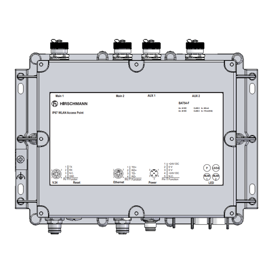
Page 19: Interfaces And Control Elements
Interfaces and control elements 1.2.1 BAT54-F The device is equipped with the following connectors and operation elements: AUX 1 Main 1 Main 2 AUX 2 BAT54-F Uin : 24 VDC CLASS 2 Iin : 400 mA Uin : 48 VDC... -
Page 20: Bat54-F Single
1.2.2 BAT54-F Single The device is equipped with the following connectors and operation elements: Main 1 Main 2 AUX 1 AUX 2 BAT54-F Uin : 24 VDC CLASS 2 Iin : 400 mA Uin : 48 VDC CLASS 2 Iin : 170 mA (PoE) -
Page 21: Bat54-F Client
1.2.3 BAT54-F Client The device is equipped with the following connectors and operation elements: Main 1 Main 2 AUX 1 AUX 2 BAT54-F Uin : 24 VDC CLASS 2 Iin : 400 mA Uin : 48 VDC CLASS 2 Iin : 170 mA (PoE) -
Page 22: Bat300-F
The device is equipped with the following connectors and operation elements: Main 1 Main 2 AUX 1 AUX 2 BAT54-F Uin : 24 VDC CLASS 2 Iin : 400 mA Uin : 48 VDC CLASS 2 Iin : 170 mA (PoE) -
Page 23: Bat54-Rail
1.2.5 BAT54-Rail The device is equipped with the following connectors and operation elements: Main 1 Main 2 WLAN1 WLAN2 BAT54-Rail Aux1 Aux2 Interfaces and display and control elements ETH1 First Ethernet port 10/100BASE-TX, Autosensing, Power over Ethernet (PoE), automatic MDI/ MDIX recognition (no crossover cable required) +24V Power, power supply connector for safety extra-low voltage (SELV/PELV) -
Page 24: Bat54-Rail Single
1.2.6 BAT54-Rail Single The device is equipped with the following connectors and operation elements: Main WLAN +24V +24V BAT54-Rail Single Reset V.24 12V DC Interfaces and display and control elements Ethernet port: 10/100BASE-TX, Autosensing, Power over Ethernet (PoE), automatic MDI/ MDIX recognition (no crossover cable required) +24V Power, power supply connector for safety extra-low voltage (SELV/PELV) -
Page 25: Bat54-Rail Client
1.2.7 BAT54-Rail Client The device is equipped with the following connectors and operation elements: Main BAT54-Rail Client Interfaces and display and control elements Ethernet port: 10/100BASE-TX, Autosensing, Power over Ethernet (PoE), automatic MDI/ MDIX recognition (no crossover cable required) +24V Power, power supply connector for safety extra-low voltage (SELV/PELV) 12V DC Power, power supply connector for safety extra-low voltage (SELV/PELV) -
Page 26: Bat300-Rail
1.2.8 BAT300-Rail The device is equipped with the following connectors and operation elements: BAT300-Rail Interfaces and display and control elements ETH1 First Ethernet port 10/100BASE-TX, Autosensing, Power over Ethernet (PoE), automatic MDI/ MDIX recognition (no crossover cable required) +24V Power, power supply connector for safety extra-low voltage (SELV/PELV) 12V DC Power, power supply connector for safety extra-low voltage (SELV/PELV) V.24... -
Page 27: Device Models
Outdoors, also under extreme conditions, including environments with the danger of explosions BAT54-F Client Outdoors, also under extreme conditions BAT54-F Client FCC Outdoors, also under extreme conditions BAT54-F Single Outdoors, also under extreme conditions BAT54-F Single FCC Outdoors, also under extreme conditions... -
Page 28: Bat54-Rail Devices
1.3.2 BAT54-Rail devices Device Area of application BAT54-Rail DIN rail and flat surface mounting BAT54-Rail - FCC DIN rail and flat surface mounting BAT54-Rail - Japan DIN rail and flat surface mounting BAT54-Rail Client DIN rail and flat surface mounting BAT54-Rail Client (FCC) DIN rail and flat surface mounting BAT54-Rail Single DIN rail and flat surface mounting... -
Page 29: Bat-Bg/Bgn Devices
BAT300-F BGN Using the 2.4 GHz ISM wave band Higher radio output and more stable network coverage through MIMO with 3 antennas BAT54-F Client BG Using the 2.4 GHz ISM wave band Outdoors, also under extreme conditions BAT54-F Single BG Using the 2.4 GHz ISM wave band... -
Page 30: Assembly And Start-Up
Assembly and start-up Installing the device The devices have been developed for practical application in a harsh industrial environment. On delivery, the device is ready for operation. The following procedure has been proven to be successful for the assembly of the device: Unpacking and checking Putting components together (BAT-F) Selecting the location for mounting/setting up... -
Page 31: Putting Components Together (Bat-F)
Putting components together (BAT-F) To protect the exposed contacts of the components from dirt, the individual system components must be connected in a dry and clean area. Seal unused ports with the cover caps supplied. Note: Connectors are not electrical isolating devices. Therefore, first plug the connector into the power supply plug, then switch on the power supply. - Page 32 When implementing your lightening protection concept, make sure you meet the requirements of standards VDE 0182 and IEC 62305. Hirschmann recommends using the Hirschmann BAT Protector as a lightening protection (see on page 62 „Accessories“).
-
Page 33: Pole Mounting
2.5.2 Pole mounting The BAT-F devices are suitable for pole mounting with the additional BAT-F pole mounting set (see on page 62 „Accessories“). The BAT-F pole mounting set is designed for: Pole diameter: 37 mm to 60 mm Maximum permitted wind load: 220 km/h. Figure 4: BAT-F pole mounting set DIN rail mounting (BAT-Rail) Mount the device on a 35 mm DIN rail in accordance with DIN EN 60175. -
Page 34: Flat Surface Mounting
Figure 5: Mounting on the DIN rail Flat surface mounting 2.7.1 BAT-F Prepare the drill holes at the installation point. Mount the device on a flat surface with four M5 screws. Figure 6: BAT-F, mounting on a flat surface (e.g. wall) BAT-F, BAT-Rail, BAT54, BAT300 Release 02 07/10... -
Page 35: Bat-Rail
2.7.2 BAT-Rail a i l Figure 7: BAT-Rail, wall mounting Fasten on the wall mounting plate (width 120 mm / 4.73 in) (see on page 62 „Accessories“) on a level wall surface using four screws. Mount the device on the wall plate as shown in the illustration. Attach the upper snap-in guide of the device into the rail and press it down against the rail until it snaps into place. - Page 36 IP67 WLAN Access Point LS/DA N.C. LS/DA WLAN Function Function Function Ethernet 1 V.24 Reset Ethernet 2 BAT54-F Single Figure 9: Connections for external antennas on BAT54-F Single 1 - Main 2 - AUX BAT-F, BAT-Rail, BAT54, BAT300 Release 02 07/10...
- Page 37 N.C. WLAN Function Function Function V.24 Ethernet Reset Power BAT54-F Client Figure 10: Connections for external antennas on BAT54-F Client 1 - Main 2 - AUX BAT300-F Antenna 1 Antenna 2 Antenna 3 BAT300-F Uin : 24 VDC CLASS 2...
-
Page 38: Connections For External Antennas On Bat-Rail
2.8.2 Connections for external antennas on BAT-Rail BAT54-Rail The devices have four Reverse SMA antenna connectors for connecting external antennas. WLAN1 WLAN2 BAT54-Rail Aux1 Aux2 Figure 12: Connections for external antennas on BAT54-Rail 1 - Antenna 1 2 - Antenna 2 3 - Aux1 4 - Aux2 BAT54-Rail Single... - Page 39 BAT54-Rail Client The devices have two Reverse SMA antenna connectors for connecting external antennas. Main BAT54-Rail Client Figure 14: Connections for external antennas on BAT54-Rail Client 1 - Main 2 - Aux BAT300-Rail The devices have three Reverse SMA antenna connectors for connecting external antennas.
-
Page 40: Mounting External Antennas
2.8.3 Mounting external antennas Connect the external antenna to the corresponding ‘Antenna Main’ connection. If you only want to connect one antenna with only one connection for each radio module, you use the main connection. BAT54 types: Use the respective main connection of the two WLAN modules to connect antennas that have only one antenna connection without diversity. -
Page 41: Grounding
- and fasten the screw. Make sure that the ground wire is not in direct contact with the aluminum housing of the device. Figure 16: BAT54-F ground connection 1 - Fastening plates for ground wire 2 - Ground wire 2.10.2... -
Page 42: Connecting The Supply Voltage
N.C. (not used) Power Table 2: Pin assignment of the 5-pin M12 connector on the BAT-F Note: For the BAT54-F, the voltage supply is exclusively via PoE (see page 43 „Power over Ethernet (PoE) - power supply via the LAN cable“). -
Page 43: Power Over Ethernet (Poe) - Power Supply Via The Lan Cable
Power over Ethernet (PoE) - power supply via the LAN cable Hirschmann Wireless Routers are prepared for the PoE (Power over Ethernet) procedure and conform to the 802.3af standard. PoE-capable network devices can be supplied with power via the LAN cable. This makes it unnecessary to have a separate power supply for every base station, thus considerably reducing the work involved in the installation. -
Page 44: Connecting The Data Lines
2.12 Connecting the data lines 2.12.1 10/100 Mbit/s twisted pair connection In the BAT-F, the 10/100 Mbit/s twisted pair connections are M12 sockets. 10/100 Mbit/s ports enable the connection of terminal devices or independent network segments according to the IEEE 802.3 100BASE-TX / 10BASE-T standard. -
Page 45: 10/100 Mbit/S Twisted Pair Connection
(10) Figure 17: Patch cables for operating the device (1) - Connection cables M12-4 on M12-4, crossed (2) - Connection cables M12-4 on M12-4, 1 to 1 (3) - Connection cables M12-4 on RJ45, crossed (4) - Connection cables M12-4 on RJ45, 1 to 1 (5) - M12 (MDI) (6) - Shield (7) - M12 (MDI) -
Page 46: Installing The Bat-F X2 Housing Cover
State on delivery: autonegotiation activated. The socket housing is electrically connected to the bottom panel. Figure Function Receive Data + Receive Data - Transmit Data + Transmit Data - 4,5,7,8 Not used Table 5: Pin assignment of a TP/TX interface in MDI-X mode, RJ45 socket 2.13 Installing the BAT-F X2 housing cover For use in environments with the danger of explosions, the BAT-F X2 device... -
Page 47: Startup Procedure
Figure 18: Mounting the housing cover for BAT-F X2 device models with Ex certification in accordance with ATEX 95 (ATEX 100a) 2.14 Startup procedure 2.14.1 BAT-F Connecting the voltage supply via the 5-pin M12 connector or via the LAN cable (Power over Ethernet) starts the operation of the device. 2.14.2 BAT-Rail Connecting the voltage supply via the terminal block... -
Page 48: Finding And Configuring Devices
2.15 Finding and configuring devices Note: Apply power to the device before starting the computer for the configuration. AP / AC devices can be configured in the following ways (if the model is equipped with the corresponding interface): Via the local network (LAN). Via the radio network (WLAN), if the WLAN encryption (e.g. - Page 49 Open the configuration for the physical interface to which you are connecting the antenna. On the Radio tab you will find an entry field for the antenna gain (see the following figure): BAT-F, BAT-Rail, BAT54, BAT300 Release 02 07/10...
-
Page 50: Display Elements
Subtract the cable attenuation and any losses due to over voltage protector installed devices from the antenna gain, and enter the result in dB in the antenna gain field. 2.17 Display elements After the operating voltage is applied, the software starts and initializes itself. The device then performs a self-test. - Page 51 BAT300-F BAT54-F Client LS/DA LS/DA WLAN WLAN Figure 19: Display elements for the BAT54-F, BAT54-F Single, BAT300-F, BAT54-F Client 1 - P (Power) 2 - LS/DA (Ethernet port link status/data) 3 - WLAN 1 4 - WLAN 2 5 - NC...
-
Page 52: Device Status
2 - Ethernet port data (DA) 3 - Power (P) 4 - WLAN1 5 - WLAN2 6 - M1 Meaning of the LEDs The behavior of the LEDs is described below: Blinking means that the LED switches on and off at regular intervals in the color specified. -
Page 53: Operation Element (Reset Button)
Port Status - Ethernet Port These LEDs display port-related information. LS/DA Data, link status (green/yellow LED) Status of the LAN interfaces No network device connected Green on continuously Ethernet connection active Yellow flickering Data traffic 2.18 Operation element (reset button) In the AP / AC family devices, the operating elements include a reset button. -
Page 54: Bat-Rail
When you want to use the reset button, remove the cover cap. Note: After pressing the reset button, replace the cover cap. Protection class IP67 is only achieved when the cover cap is closed. 2.18.3 BAT-Rail In the BAT-Rail, the reset button (see (1) in the following figure) is located on the front plate of the device. - Page 55 ACA 11. This enables you to set up a connection to the Command Line Interface (CLI) and to the system monitor. Caution! Available as an accessory for certain Hirschmann devices, the AutoConfiguration Adapter ACA21-M12 is not designed to be used with BAT-F devices.
-
Page 56: Disassembly
Figure Function Clear to send Request to send Receive data Ring indicator Transmit data Dataset ready Data carrier detect Data terminal ready Ground Table 7: Pin assignment of the V.24 interface for BAT-Rail (miniDin socket) Note: You will find the order number for the terminal cable, which is ordered separately, in the ”Technical Data”... -
Page 57: Technical Data
BAT54-F 2 x WLAN interfaces, up to 8 SSIDs per WLAN interface, number 1 x LAN port 10/100BASE-TX, Autosensing BAT54-F Single 1 x WLAN interface, up to 8 SSIDs per WLAN interface, 2 x LAN ports 10/100BASE-TX, Autosensing BAT54-F Client... - Page 58 - designed for mounting on a DIN rail or on a flat surface (e.g. wall) Radio technology Antenna BAT54-F Four antenna connections connection BAT54-F Single Two antenna connections BAT54-F Client Two antenna connections BAT300-F Three antenna connections BAT54-Rail Four Reverse SMA antenna connections (sockets)
- Page 59 Radio topology BAT... WLAN access point, bridge, router, point-to-point, client, client-bridge mode, fixed mesh with RSTP BAT Client WLAN client, client-bridge mode Roaming BAT... Seamless handover, IAPP support, IEEE802.11d support, background scanning for rogue AP detection and fast roaming Transmission BAT54 2.4 GHz 802.11b: +19 dBm @1 and 2 Mbit/s, +19 dBm @ power...
- Page 60 IEC 60068-2-27 Test Ea test level in accordance with IEC 61131-2, EN 50155:2001+A1:2002 Shock resistance IEC 60079-0 chap. 6.2 BAT54-F X2 and Shock resistance test with 1kg mass dropped from 0.7 m BAT54-F X2 FCC Housing cover only removeable with tool...
- Page 61 BAT54-F FCC 10.0 W 34.1 Btu (IT)/h 943 959-012 BAT54-F X2 10.0 W 34.1 Btu (IT)/h 943 959-102 BAT54-F X2 FCC 10.0 W 34.1 Btu (IT)/h 943 959-002 BAT54-F Client 10.0 W 34.1 Btu (IT)/h 943 959-117 BAT54-F Client FCC 10.0 W...
-
Page 62: Scope Of Delivery
Scope of delivery Device Scope of delivery Device Installation user manual in German and English CD ROM with following content: - Management software LANconfig - Monitoring software LANmonitor and WLANmonitor - Installation user manual in PDF format in German/English - User manual in PDF format in German/English - Reference manual in PDF format in German/English - HiLCOS operating system as upx file 50 Ohm connection... - Page 63 Name Order number Pocket Guide 280 710-851 Terminal cable 943 301-001 6-pin terminal block 943 845-002 Rail Power Supply RPS 30 943 662-003 Rail Power Supply RPS 80 EEC 943 662-080 Rail Power Supply RPS 120 EEC 943 662-120 Industrial HiVision Network Management software 943 156-xxx Note: Products recommended as accessories may have characteristics that do not fully correspond to those of the corresponding product.
- Page 64 The following table shows the status of the certification of the equipment. Standard EN 60079-15 (ATEX95) pending Table 10: Certifications - see www.hirschmann-ac.com for current status. For further information on other notifications or certifications, contact inet- sales@belden.com Certifications The following table shows the status of the device certifications.
- Page 65 Further support Technical questions and training courses In the event of technical queries, please contact your local Hirschmann distributor or Hirschmann office. You can find the addresses of our distributors on the Internet: www.hirschmann-ac.com. Our support line is also at your disposal: Tel.
Need help?
Do you have a question about the BAT54-F and is the answer not in the manual?
Questions and answers