Rotax 912 i Series Installation Manual
Hide thumbs
Also See for 912 i Series:
- Maintenance manual (448 pages) ,
- Operator's manual (90 pages) ,
- Service instructions manual (18 pages)
Table of Contents
Advertisement
Advertisement
Chapters
Table of Contents

Related Manuals for Rotax 912 i Series


Summary of Contents for Rotax 912 i Series
- Page 1 AIRCRAFT ENGINES ref. no.: IM-912 i | part no.: 898647...
- Page 2 This Installation Manual for the ROTAX aircraft engines should only be used as a general ® installation guide for the installation of ROTAX engines into airframes. It should not be used as ® instruction for the installation of a ROTAX aircraft engine in a specific type of airframe or airplane.
- Page 3 If any passages of this Manual are not clearly understood or if you have any questions, please contact an authorized distributor- or Service Center for ROTAX aircraft engines. BRP-Powertrain GmbH & Co KG (hereinafter “BRP-Powertrain“) wishes you much pleasure and satisfaction flying your aircraft powered by this ROTAX aircraft engine.
- Page 4 BRP-Powertrain INSTALLATION MANUAL NOTES INTRO Effectivity: 912 i Series Edition 1/Rev. 0 page 2 January 01/2012...
- Page 5 01 01 2012 01 01 2012 01 01 2012 01 01 2014 01 01 2012 01 01 2012 01 01 2012 01 01 2012 01 01 2012 01 01 2012 Effectivity: 912 i Series Edition 1/Rev. 2 page 1 January 01/2014...
- Page 6 01 01 2012 01 01 2012 01 01 2012 07 01 2012 01 01 2012 01 01 2012 01 01 2012 01 01 2012 01 01 2012 01 01 2012 Effectivity: 912 i Series Edition 1/Rev. 2 page 2 January 01/2014...
- Page 7 01 01 2012 01 01 2012 01 01 2012 80-00-00 01 01 2012 01 01 2012 01 01 2012 01 01 2012 01 01 2012 01 01 2012 Rear page Effectivity: 912 i Series Edition 1/Rev. 2 page 3 January 01/2014...
- Page 8 BRP-Powertrain INSTALLATION MANUAL NOTES Effectivity: 912 i Series Edition 1/Rev. 0 page 4 July 01/2012...
-
Page 9: Table Of Amendments
DOA* 1,2,3 01 01 2014 DOA* 00-00-00 8,9,11,12 01 01 2014 DOA* 24-00-00 1,3-36 01 01 2014 DOA* 61-00-00 01 01 2014 DOA* 72-00-00 7,8,9 01 01 2014 DOA* Effectivity: 912 i Series Edition 1/Rev. 2 page 1 January 01/2014... - Page 10 73-00-00 1-16 01 01 2014 DOA* 75-00-00 17-22 01 01 2014 DOA* 76-00-00 1-16 01 01 2014 DOA* 78-00-00 1,5,6,7,9-14 01 01 2014 DOA* Effectivity: 912 i Series Edition 1/Rev. 2 page 2 January 01/2014...
- Page 11 2014 01 01 Chap. 2 Exhaust requirements: Text 7,9-14 Chap. 2.2 If a genuine ROTAX exhaust is not used: Text Chap. 3 Installation of the exhaust system: Text deleted Chap. 4 Change of text Chap 4.1 Exhaust system assy.: New graphic Effectivity: 912 i Series Edition 1/Rev.
- Page 12 BRP-Powertrain INSTALLATION MANUAL NOTES Effectivity: 912 i Series Edition 1/Rev. 0 page 4 July 01/2012...
-
Page 13: Table Of Contents
This section describes the installation of engine type ROTAX Introduction 912 i Series. NOTE: ROTAX 912 i Series includes 912 iSc and 912 iS. This chapter of the Installation Manual contains general and safety infor- Table of contents mation concerning the operation and maintenance of the aircraft engine. - Page 14 BRP-Powertrain INSTALLATION MANUAL NOTES 00-00-00 Effectivity: 912 i Series Edition 1/Rev. 0 page 2 January 01/2012...
-
Page 15: General Note
For additional information on engines, maintenance or parts, you can also contact your nearest authorized ROTAX-aircraft engine distributor. For ROTAX Authorized Distributors for Aircraft Engines see latest Opera- ROTAX Distributors tors Manual or on the Internet at the official Website www.FLYROTAX.com. -
Page 16: Type Description
Available options (optional equipment) for the engine type mentioned Options above: external vacuum exhaust governor alternator pump system for configuration 2 for configuration 3 00-00-00 Effectivity: 912 i Series Edition 1/Rev. 1 page 4 July 01/2012... -
Page 17: Standard Version
- Fuel pump assy. - Preparation for hydraulic governor for constant speed propeller: (con- Optional figuration 3 only) - Exhaust system - Cooling air baffle - Engine suspension frame Effectivity: 912 i Series 00-00-00 Edition 1/Rev. 2 page 5 January 01/2014... - Page 18 Components especially developed and tested for this engine are readily available at BRP-Powertrain. The following auxiliary equipment has been tested on ROTAX engine type 912 i for safety and durability to the standards of aviation. The furnishing of proof in accordance to the latest FAR or EASA has to be conducted by the aircraft manufacturer.
-
Page 19: Abbreviations And Terms Used In This Manual
Cooling Temperature Sensor Clockwise Counter-clockwise DCDI Dual Capacitor Discharge Ignition d.c. direct current Design Organisation Approval Department of Transport EASA European Aviation Safety Agency Engine Control Unit Exhaust Gas Temperature Effectivity: 912 i Series 00-00-00 Edition 1/Rev. 0 page 7 January 01/2012... - Page 20 Rev. Revision Research Octane Number ROTAX is a trade mark of BRP-Powertrain GmbH & Co KG Revolutions per minute Service Bulletin Service Instruction Service Letter Surface Mounted Devices 00-00-00 Effectivity: 912 i Series Edition 1/Rev. 2 page 8 January 01/2014...
- Page 21 Time Between Overhaul Table of amendments Table of Contents Time Since New TSNP Time Since New Part Time Since Overhaul Volt Visual Flight Rules shows the serial component number Effectivity: 912 i Series 00-00-00 Edition 1/Rev. 2 page 9 January 01/2014...
-
Page 22: Conversion Table
21 13 8.4 5.3 3.3 2.1 1.3 0.8 0.52 1 bar = 100000 Pa/1000 hPa/ 100 kPa 1 bar = 14.5037 lbf/in (psi) 1 in Hg = 33.8638 hPa 00-00-00 Effectivity: 912 i Series Edition 1/Rev. 0 page 10 January 01/2012... -
Page 23: Safety Notice
Environmental notes give you tips on environmental behavior. A revision bar outside of the page margin indicates a change to text or graphic. This information gives you additional advice and tips. WARNUNG Effectivity: 912 i Series 00-00-00 Edition 1/Rev. 2 page 11 January 01/2014... -
Page 24: Safety Information
- Where differences exist between this Manual and regulations provided by any authority, the more stringent regulation should be applied. 00-00-00 Effectivity: 912 i Series Edition 1/Rev. 2 page 12 January 01/2014... - Page 25 - Improper engine installation and use of unsuitable piping for fuel, cool- ing and lubrication system releases the engine manufacturer from any liability. Effectivity: 912 i Series 00-00-00 Edition 1/Rev. 0 page 13 January 01/2012...
-
Page 26: Instruction
(see IPC) or suitable equivalent in the manufactur- er’s opinion otherwise, any limited warranty by BRP- Powertrain is null and void (see Warranty Conditions). Spare parts are available at the authorized ROTAX Distributor and their Service Center. Any warranty by BRP-Powertrain becomes null and... -
Page 27: Technical Documentation
The status of the Manuals can be determined with the aid of the table of Status amendments. The first column indicates the revision state. This figure should be compared with the revision provided on ROTAX- Aircraft Engines Website: www.FLYROTAX.com. Amendments and current versions can be downloaded free of charge. - Page 28 This number (e.g. 00277) is of no significance for the con- tent. Installation drawings and a DMU-model for (virtual) installation analysis Installation drawings are available from the ROTAX Authorized Distributors or their Service Centers. 00-00-00 Effectivity: 912 i Series Edition 1/Rev. 0...
- Page 29 BRP-Powertrain INSTALLATION MANUAL Installation drawing Graphic Effectivity: 912 i Series 00-00-00 Edition 1/Rev. 0 page 17 January 01/2012...
- Page 30 BRP-Powertrain INSTALLATION MANUAL NOTES 00-00-00 Effectivity: 912 i Series Edition 1/Rev. 0 page 18 January 01/2012...
- Page 31 Page 4 Engine suspension and installation position Page 6 Engine suspension instructions Page 6 Attachment points Page 8 Definition of attachment points Page 9 Permissible installation positions Page 11 Effectivity: 912 i Series 10-10-00 Edition 1/Rev. 0 Page 1 January 01/2012...
- Page 32 BRP-Powertrain INSTALLATION MANUAL NOTES 10-10-00 Effectivity: 912 i Series Edition 1/Rev. 0 Page 2 January 01/2012...
-
Page 33: Preparations For Engine Installation
The engine can be attached with steel angles anchored on a timber plate. - When the engine is delivered, check that the GENUINE-ROTAX pack- ing is not damaged. - If the packing is damaged, contact the authorized distributor- or Ser- vice Center for ROTAX aircraft engines. -
Page 34: Preservation And Storage Of The Engine
BRP-Powertrain. This warranty is subject to the following conditions: Warranty - The engine must be stored in the GENUINE-ROTAX packing as sup- plied by BRP-Powertrain. - The covers on various openings must not be removed. - The engine must be stored in a suitable place (at min. -40 °C/-40 °F and max. - Page 35 Exhaust sockets Fuel rail (outlet) / fuel pressure regulator Fuel rail (inlet) Oil inlet/outlet Supply and discharge of coolant Throttle valve support assy. Propeller shaft Graphic Fig. 2 Effectivity: 912 i Series 10-10-00 Edition 1/Rev. 0 Page 5 January 01/2012...
-
Page 36: Engine Suspension And Installation Position
The engine suspension must be designed to prevent NOTICE WARNUNG and vibration excessive engine movement and to minimise noise emission and vibration on the airframe. If the GENUINE-ROTAX engine suspension frame is NOTICE WARNUNG not being used, a vibration test must be carried out. See SL-912-010. 10-10-00 Effectivity: 912 i Series Edition 1/Rev. - Page 37 All elements for neutralising vibrations must be cap- NOTICE WARNUNG ments tive. The y-axis must be perpendicular to the longitudinal axis of the aircraft. Vertical axis Permissible deviation from perpendicular: 10°. Deviation Fig. Effectivity: 912 i Series 10-10-00 Edition 1/Rev. 0 Page 7 January 01/2012...
-
Page 38: Attachment Points
A minimum of 4 attachment points must be used. NOTICE WARNUNG These must be distributed symmetrically between the left (L) and right (R) sides. 10-10-00 Effectivity: 912 i Series Edition 1/Rev. 0 Page 8 January 01/2012... -
Page 39: Definition Of Attachment Points
Tighten all engine suspension screws as specified by the aircraft manufacturer. Attachment points Graphic Fig. 5 Effectivity: 912 i Series 10-10-00 Edition 1/Rev. 0 Page 9 January 01/2012... - Page 40 5000/196.85 2000/78.74 3000/118.11 100/3.94 Max. usable Attachment points Thread Thread length 25 mm/0.98 in. 16 mm/0.63 in. 10-10-00 Effectivity: 912 i Series Edition 1/Rev. 0 Page 10 January 01/2012...
-
Page 41: Permissible Installation Positions
- Installation only with propeller shaft above cylinders The centres of attachment points L1 and R1 must be on a y2 axis parallel Propeller axis to the y-axis. Permissible deviation from parallel: ±5° Fig. 6 Effectivity: 912 i Series 10-10-00 Edition 1/Rev. 0 Page 11 January 01/2012... - Page 42 BRP-Powertrain INSTALLATION MANUAL The y-axis must be perpendicular to the longitudinal axis of the aircraft. Vertical axis Permissible deviation from perpendicular: ±10° Fig. 7 10-10-00 Effectivity: 912 i Series Edition 1/Rev. 0 Page 12 January 01/2012...
- Page 43 Wiring diagram: Wiring Powerside Page 32 Wiring diagram: Wiring Powerside (optional) Page 33 Wiring diagram: Wiring HIC switch and warning lamps Page 34 Internal power consumers Page 35 Effectivity: 912 i Series 24-00-00 Edition 1/Rev. 2 Page 1 January 01/2014...
- Page 44 BRP-Powertrain INSTALLATION MANUAL NOTES 24-00-00 Effectivity: 912 i Series Edition 1/Rev. 0 Page 2 January 01/2012...
-
Page 45: Requirements For The Circuit Wiring
NOTE: Follow the relevant building regulations (licensing condi- tions) of the maintenance staff, during manufacturing of the wiring harness and repairs or modifications of the air- craft. Effectivity: 912 i Series 24-00-00 Edition 1/Rev. 2 Page 3 January 01/2014... -
Page 46: Approval Of Electric And Electronic Components
* ....Components were tested at „operating low temperature“ of - 25° C (- 13° F) instead of - 45° C (- 49° F) and „Altitude“ of 18.000 ft instead of 25.000 ft. 24-00-00 Effectivity: 912 i Series Edition 1/Rev. 2 Page 4 January 01/2014... -
Page 47: Battery
The responsibility is up to the aircraft manufacturer. The consent and approval of the relevant aeronautical authority is necessary. Effectivity: 912 i Series 24-00-00 Edition 1/Rev. 2 Page 5 January 01/2014... - Page 48 The connection from the battery to the EMS system NOTICE WARNUNG must be kept separate from the one to the starter relay in order to avoid unnecessary voltage drop. 24-00-00 Effectivity: 912 i Series Edition 1/Rev. 2 Page 6 January 01/2014...
-
Page 49: Grounding Cables (Ems Ground Point/Engine/Ground Point)
EMS ground must be mounted to the regulator plate A (heat sink of the fuse box) only. Aircraft ground must be mounted on the regulator plate B (heat sink of the fuse box) only. Effectivity: 912 i Series 24-00-00 Edition 1/Rev. 2 Page 7... -
Page 50: Controller Boards On The Fuse Box
The tightening torque of the nuts to secure the EMS NOTICE WARNUNG grounding cables and the airframe ground of the re- spective attachment points must be 1.2 Nm (10.7 in.lb). 24-00-00 Effectivity: 912 i Series Edition 1/Rev. 2 Page 8 January 01/2014... - Page 51 BRP-Powertrain INSTALLATION MANUAL FUSE BOX Graphic Part Function EMS ground attachment points Fig. 2 09544 Effectivity: 912 i Series 24-00-00 Edition 1/Rev. 2 Page 9 January 01/2014...
-
Page 52: Fuse Box Connections
Rectifier regulator B (grey plug) Plug connection X1 (LANE A) Plug connection X2 (LANE B) Plug connection X3 EMS ground (Generator A) Aircraft ground (Generator B) Fig. 3 24-00-00 Effectivity: 912 i Series Edition 1/Rev. 2 Page 10 January 01/2014... -
Page 53: Technical Data And Connection Of The Electric Components
Performance diagram showing engine speed against amps Graphic Stator 912 iS 30,00 Generator B 25,00 20,00 15,00 Generator A 10,00 5,00 0,00 1000 2000 3000 4000 5000 6000 Engine Speed [rpm] Fig. 4 06591 Effectivity: 912 i Series 24-00-00 Edition 1/Rev. 2 Page 11 January 01/2014... - Page 54 DEUTSCH connector: - black for generator A/regulator A - grey for generator B/regulator B Connections Graphic Part Function Stator DEUTSCH connector FUSE BOX with rectifier regulator Fig. 5 24-00-00 Effectivity: 912 i Series Edition 1/Rev. 2 Page 12 January 01/2014...
-
Page 55: Rectifier Regulator
The performance specifications are given for optimal cooled components. See chap. 72-00-00 section 2) Subsection 2.1: Weight. Weight Component temperature measurement area Graphic Part Function Rectifier regulator Component temperature measuring area Fig. 6 06385 Effectivity: 912 i Series 24-00-00 Edition 1/Rev. 2 Page 13 January 01/2014... - Page 56 BRP-Powertrain INSTALLATION MANUAL NOTES 24-00-00 Effectivity: 912 i Series Edition 1/Rev. 2 Page 14 January 01/2014...
-
Page 57: External Alternator (Optional Extra)
46225 (tightening torque 4 Nm (35 in.lb)). Via engine block. Grounding Control wiring (3): Control wiring - via supplied standard plug (Sumitomo 6111-2568) and 6.3 x 0.8 Faston connectors (female). Effectivity: 912 i Series 24-00-00 Edition 1/Rev. 2 Page 15 January 01/2014... - Page 58 Due to slightly different output voltages of the regulators (alternator and Load distribution regulator A/B of fuse box) the power is drawn by the generator with the higher output voltage at low load. 24-00-00 Effectivity: 912 i Series Edition 1/Rev. 2 Page 16 January 01/2014...
- Page 59 3 times the propeller speed. Graphic 1/min. / rpm. n Propeller 1000 1500 2000 2500 rpm. propeller 2000 3000 4000 5000 6000 7000 8000 n Generator rpm. alternator Fig. 8 00547 Effectivity: 912 i Series 24-00-00 Edition 1/Rev. 2 Page 17 January 01/2014...
- Page 60 External alternator Effectivity: 912 i Series Page 18 Edition 1/Rev. 2 January 01/2014...
-
Page 61: Wiring Harness
The sensors are fitted by BRP-Powertrain and connected to the wiring Sensors harness. The exhaust gas temperature sensors are included according to the version or already fitted on GENUINE-ROTAX exhaust systems. Install and lock the connectors of the ECU and/or FUSE BOX with gas- ECU/FUSE BOX connector ket. -
Page 62: Fitting The Faston Connector To The Harness Interface
Connector receptacle until it is locked in place (C). Check for tight fit. NOTE: The TPA pin holder must not be pressed pushed with ex- cessive force. 24-00-00 Effectivity: 912 i Series Edition 1/Rev. 2 Page 20 January 01/2014... - Page 63 CAN_GND_1_A CONN_STARTER_REL_SW CAN_LOW_1_A CAN_HIGH_1_A CAN_GND_1_B LANE_SEL_SW_A_2 CAN_LOW_1_B WARN_LAMP_A CAN_HIGH_1_B GND_FUEL_PUMP_1 LANE_SEL_SW_B_2 CAN_GND_2_A WARN_LAMP_B CAN_LOW_2_A GND_FUEL_PUMP_2 CAN_HIGH_2_A SUPP_START_SWITCH CAN_GND_2_B CAN_LOW_2_B CAN_HIGH_2_B Maintenance Port LANE A Maintenance Port LANE B Effectivity: 912 i Series 24-00-00 Edition 1/Rev. 2 Page 21 January 01/2014...
- Page 64 BRP-Powertrain INSTALLATION MANUAL Harness Interface Connector (HIC) Graphic Part Function HIC A-pin 1 to 12 HIC B-pin 1 to 16 Fig. 11 24-00-00 Effectivity: 912 i Series Edition 1/Rev. 2 Page 22 January 01/2014...
-
Page 65: Switch And Warning Lamp Requirements
FUEL PUMP SWITCH 1 Requirement Connector/slot Switch type Toggle-SPST HIC A Nominal voltage 28 VDC Nominal current 10 A Number of poles 1-pole Designation on wiring harness SIG_FUEL_PUMP_1 GND_FUEL_PUMP_1 Effectivity: 912 i Series 24-00-00 Edition 1/Rev. 2 Page 23 January 01/2014... - Page 66 WARNING LAMP B Requirement Connector/slot Lamp colour In accordance with the regulati- HIC B Nominal voltage 12 V Nominal current Maximum 120 mA Designation on wiring harness SUPP_WARN_LAMP_B WARN_LAMP_B 24-00-00 Effectivity: 912 i Series Edition 1/Rev. 2 Page 24 January 01/2014...
- Page 67 Push button HIC B Nominal voltage 28 VDC Nominal current Number of poles 1-pole Designation on wiring harness CONN_STARTER_REL_SW SUPP_START_SWITCH * optionally a key switch can be used. Effectivity: 912 i Series 24-00-00 Edition 1/Rev. 2 Page 25 January 01/2014...
-
Page 68: Tips: Wiring Powerside (Optional)
Position of the key switch Pins Master relay HIC B Pin 4 Airframe Ground HIC B Pin 12 Aircraft/Engine Status Off Engine Start Master Relay Open Closed Closed 24-00-00 Effectivity: 912 i Series Edition 1/Rev. 2 Page 26 January 01/2014... - Page 69 Tbd from aircraft manufacturer Min. control voltage Min. 6 V; Max. 18 V Number of poles SPST NO (normally open) Designation on wiring harness Not connected to the wiring har- ness. Effectivity: 912 i Series 24-00-00 Edition 1/Rev. 2 Page 27 January 01/2014...
- Page 70 KEY SWITCH (optional) Requirement Connector/slot Switch type Off/ON Nominal voltage 28 VDC Nominal current Number of poles 2-pin Designation on wiring harness Not connected to the wiring har- ness. 24-00-00 Effectivity: 912 i Series Edition 1/Rev. 2 Page 28 January 01/2014...
-
Page 71: Wiring Diagram
(wires, contact points, relay contacts) largely determine the per- formance of the starting system. Therefore, the total loop resistance ) may not exceed 0.015 Ω. Smax Σ R = R iBatt C Starter relay Other Smax Effectivity: 912 i Series 24-00-00 Edition 1/Rev. 2 Page 29 January 01/2014... - Page 72 FAR or EASA. EMS Wiring diagram. See also Page 31. Graphic Wiring power side. See also Wiring power side (optional). See also Wiring HIC Switch and warning lamp. See also 24-00-00 Effectivity: 912 i Series Edition 1/Rev. 2 Page 30 January 01/2014...
- Page 73 EMS Wiring diagram Effectivity: 912 i Series Page 31 Edition 1/Rev. 2 January 01/2014...
- Page 74 Wiring Powerside Effectivity: 912 i Series Page 32 Edition 1/Rev. 2 January 01/2014...
- Page 75 Wiring Powerside (Optional) Effectivity: 912 i Series Page 33 Edition 1/Rev. 2 January 01/2014...
- Page 76 Wiring HIC Switch and warning lamps Effectivity: 912 i Series Page 34 Edition 1/Rev. 2 January 01/2014...
-
Page 77: Internal Power Consumers
~ 400 mA NOTE: A complete analysis of the current consumption of all the fitted consumers is to be carried out by the aircraft or air- frame manufacturer. Effectivity: 912 i Series 24-00-00 Edition 1/Rev. 2 Page 35 January 01/2014... - Page 78 BRP-Powertrain INSTALLATION MANUAL NOTES 24-00-00 Effectivity: 912 i Series Edition 1/Rev. 2 Page 36 January 01/2014...
- Page 79 Subject Page Propeller drive Page 3 Technical data Page 3 Operating limits Page 4 Hydraulic governor for constant speed propeller Page 5 Technical data for connections Page 5 Effectivity: 912 i Series 61-00-00 Edition 1/Rev. 0 Page 1 January 01/2012...
- Page 80 BRP-Powertrain INSTALLATION MANUAL NOTES 61-00-00 Effectivity: 912 i Series Edition 1/Rev. 0 Page 2 January 01/2012...
-
Page 81: Propeller Drive
Direction of rotation of the propeller flange: - left, counter clockwise, looking towards face of flange Direction of rotation Graphic Fig. 1 Gear transmission: Transmission - i= 2.4286 (51 Teeth/21 T) Effectivity: 912 i Series 61-00-00 Edition 1/Rev. 2 Page 3 January 01/2014... -
Page 82: Operating Limits
- Max. extension of the propeller shaft: 120 mm (4.72 in.) Extension of propeller shaft Dynamic balancing of the propeller as specified by the propeller manufac- Out of balance turer must be carried out. 61-00-00 Effectivity: 912 i Series Edition 1/Rev. 2 Page 4 January 01/2014... -
Page 83: Hydraulic Governor For Constant Speed Propeller
Point of support x-axis mm y-axis mm z-axis mm -206.3 mm (-8.12 in.) 0 51.5 mm (2.03 in.) Crankcase flange Graphic Part Function Connection for propeller governor Governor flange Fig. 3 Effectivity: 912 i Series 61-00-00 Edition 1/Rev. 0 Page 5 January 01/2012... - Page 84 Thread length Max. 14 mm (0.55 in.) Governor drive Internal spline 20/40 SMS 1834 NA 14x1.27x30x12 Power consumption Max. 600 W Operating pressure Max. 30 bar (435 psi) 61-00-00 Effectivity: 912 i Series Edition 1/Rev. 0 Page 6 January 01/2012...
- Page 85 Centre of gravity of engine and standard Page 8 accessories Moments of inertia Page 8 Operating limits Page 9 Deviation from the apparent perpendicular Page 9 Crankshaft drive Page 11 Effectivity: 912 i Series 72-00-00 Edition 1/Rev. 1 Page 1 July 01/2012...
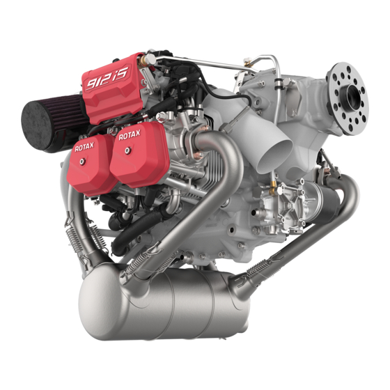
- Page 86 BRP-Powertrain INSTALLATION MANUAL Engine Overview Part Function Engine Type 912 i Series Fig. 1 72-00-00 Effectivity: 912 i Series Edition 1/Rev. 0 Page 2 January 01/2012...
-
Page 87: Engine Components, Engine Views, Cylinder Designation
Cyl. 2 Cylinder 2 Cyl. 4 Cylinder 4 Side view Part Function Engine number Propeller flange Propeller gearbox Connection for return line (tractor) Connection for return line (pusher) Fig. 2 Effectivity: 912 i Series 72-00-00 Edition 1/Rev. 0 Page 3 January 01/2012... -
Page 88: Front View
BRP-Powertrain INSTALLATION MANUAL Front view Part Function Oil filter Oil pump Exhaust flange Muffler assy. Fuel hose assy. Crankshaft locking screw position Fig. 3 08780 72-00-00 Effectivity: 912 i Series Edition 1/Rev. 0 Page 4 January 01/2012... -
Page 89: Top View, Rear View
BRP-Powertrain INSTALLATION MANUAL Top view, rear view Cyl. 4 Cyl. 3 Cyl. 2 Cyl. 1 Effectivity: 912 i Series 72-00-00 Edition 1/Rev. 0 Page 5 January 01/2012... - Page 90 Throttle valve support assy. Airbox Suspension points Dual ignition coils Expansion tank assy. Ignition housing Electric starter Water pump housing Fuel rail (right, left) Engine suspension frame (ring mount) Fig. 4 72-00-00 Effectivity: 912 i Series Edition 1/Rev. 0 Page 6 January 01/2012...
-
Page 91: Technical Data
Air filter 0.15 kg (0.33 lb) Oil cooler 0.6 kg (1.32 lb) * Can be installed original to the engine at the factory (also available as a spare part). Effectivity: 912 i Series 72-00-00 Edition 1/Rev. 2 Page 7 January 01/2014... -
Page 92: Installation Dimensions
24560 (58.282 lb ft 25450 (60.394 lb ft axis y1-y1 (kg cm Moment of inertia around 26520 (62.933 lb ft 27480 (65.211 lb ft axis z1-z1 (kg cm 72-00-00 Effectivity: 912 i Series Edition 1/Rev. 2 Page 8 January 01/2014... -
Page 93: Deviation From The Apparent Perpendicular
The resulting bank angle (depending on acceleration/deceleration) may Bank angle never exceed the max. bank angle. Pitch or roll angle is not equal with , except stabilized NOTE: condition (without acceleration). Effectivity: 912 i Series 72-00-00 Edition 1/Rev. 2 Page 9 January 01/2014... - Page 94 BRP-Powertrain INSTALLATION MANUAL Bank angle Graphic Bank or rotation Gravity Bank angle Acceleration Result of F1 and F2 Fig. 5 72-00-00 Effectivity: 912 i Series Edition 1/Rev. 0 Page 10 January 01/2012...
-
Page 95: Crankshaft Drive
Crankshaft drive Fig. 6 Fig. 7. Max. moment of inertia 15 kg cm (0.036 l b ft Part Function Plug screw M22x1,5 O-Ring 18x2.5 Support bearing Crankshaft Fig. 6 Effectivity: 912 i Series 72-00-00 Edition 1/Rev. 1 Page 11 July 01/2012... - Page 96 BRP-Powertrain INSTALLATION MANUAL Fig. 7 72-00-00 Effectivity: 912 i Series Edition 1/Rev. 1 Page 12 July 01/2012...
- Page 97 Coarse filter Page 8 Water trap Page 8 Fine filter Page 8 GENUINE- ROTAX fuel pump assy. Page 8 General requirements placed on the fuel pump Page 12 Connections for Bowden cable actuation and permissible load Page 15 Technical data...
- Page 98 If a problem with a fuel injector occurs, the fault is reported to the ECU and the pilot will be informed about a fault by the instrument panel. 73-00-00 Effectivity: 912 i Series Edition 1/Rev. 2 Page 2 January 01/2014...
-
Page 99: Fuel System
Close to fuel tank Fuel pressure sensor Part Function Fuel tank Fuel pump 1 Fuel pump 2 Fine filter Fuel pressure regulator Coarse filter/water trap Fig. 1 06293 Effectivity: 912 i Series 73-00-00 Edition 1/Rev. 2 Page 3 January 01/2014... - Page 100 BRP-Powertrain INSTALLATION MANUAL NOTES 73-00-00 Effectivity: 912 i Series Edition 1/Rev. 0 Page 4 January 01/2012...
-
Page 101: Requirements Of The Fuel System
FAR or EASA must be carried out by the aircraft manufactu- rer. See 912 i series Operators Manual, section 2.1) Operating Limits. 1.2) Fuel temperature To avoid vapour locks, the fuel temperature must not exceed 45 °C (113 °F). -
Page 102: Fuel Lines
Connection thread on the right-hand injection line (Cyl. 1/3): Inlet line M14x1.5 or AN-6 (9/16-18 UNF). The inlet line must have an inner diame- ter of minimum 7,5 mm (0.3 in.) (AN-6 or 3/8“) . 73-00-00 Effectivity: 912 i Series Edition 1/Rev. 2 Page 6 January 01/2014... - Page 103 Refer to the latest requirements such as FAR or EA- Secure fuel lines with suitable screw clamps or by crimp connection. Screw clamp Effectivity: 912 i Series 73-00-00 Edition 1/Rev. 2 Page 7...
-
Page 104: Coarse Filter
NOTE: The GENUINE ROTAX fuel pump unit has been tested and approved according to CS-3-130. Thus , the fuel pump unit can be installed to the firewall without additional fire protec- tion. - Page 105 BRP-Powertrain INSTALLATION MANUAL NOTE: The cable length for the fuel pumps can be extended, if necessary. For this a ROTAX plug kit is available. Do not connect additional load (additional fuel pumps, NOTICE WARNUNG lamps, LED, etc.) to the power supply of the fuel pumps.
- Page 106 BRP-Powertrain INSTALLATION MANUAL 1.8.2) Technical data The technical data of the fuel pumps provided by ROTAX is shown below. Graphic Fig. 2 and Fig. 3. a) Dimensions:Connection 9/16-18 UNF 73mm (2.87 in.) 14.5mm 213.5mm (8.41in.) (0.57 in.) 157mm (6.18 in.) 247.3mm (9.74in.)
- Page 107 Check valves: a) opening pressure max. 70 mbar (1.02 psi) b) resistance max. 70 mbar at 75 l/h (19.8 US gal/h) c) pressure safe up to 20 bar (290 psi) Effectivity: 912 i Series 73-00-00 Edition 1/Rev. 2 Page 11...
- Page 108 4.5 bar (65.26 psi) absolutely (at sea level) NOTE: If the length of the power supply line is insufficient, it can Power supply be extended. A ROTAX connector set is available. wires The responsibility for correct implementation and use NOTICE...
- Page 109 - Multi-tank systems without Catch-, Headertank - Coarse or fine filter not in use - Fuel cock position on the pressure side of the fuel system (after the fuel pump module) Effectivity: 912 i Series 73-00-00 Edition 1/Rev. 2 Page 13...
- Page 110 Any low points must allow for drainage of water and other contaminants. At the low points, accumulations of water can freeze WARNUNG WARNING and cut off the flow. 73-00-00 Effectivity: 912 i Series Edition 1/Rev. 2 Page 14 January 01/2014...
-
Page 111: Connections For Bowden Cable Actuation And Permissible Load
The idle speed must not be adjusted by a throttle stop in the cockpit. The Throttle lever stop throttle lever must contact the idle speed stop screw on the engine (idle speed, see latest Operators Manual). Effectivity: 912 i Series 73-00-00 Edition 1/Rev. 2 Page 15 January 01/2014... - Page 112 Adjust Bowden cable such that throttle valve can be fully opened and closed. Use Bowden cable with mini- mized friction so that the return spring on the throttle valve can open the throttle valve completely. 73-00-00 Effectivity: 912 i Series Edition 1/Rev. 2 Page 16 January 01/2014...
- Page 113 All components are installed on the aircraft engine as stan- dard. This section of the Installation Manual contains information on the aircraft Table of contents engine ignition system. Subject Page Connection to rectifier regulator Page 3 Effectivity: 912 i Series 74-00-00 Edition 1/Rev. 1 Page 1 July 01/2012...
- Page 114 Part Function Resistance spark plug connector Dual ignition coil Ignition cable FUSE BOX assy. Electrical LINE A+B with connectors Crankshaft position sensors Stator assy. Fly wheel Fig. 1 74-00-00 Effectivity: 912 i Series Edition 1/Rev. 0 Page 2 January 01/2012...
- Page 115 Generator B is used primarily to start the engine (Gener- ator B is in use till 2400 rpm longer than 3 sec, then the ECU automatically switch over to generator A) and to charge the aircraft battery. Effectivity: 912 i Series 74-00-00 Edition 1/Rev. 2 Page 3...
- Page 116 BRP-Powertrain INSTALLATION MANUAL Ignition system Graphic Part Function Internal generator Electrical LINE A+B with connectors FUSE BOX assy. Fig. 2 06326 74-00-00 Effectivity: 912 i Series Edition 1/Rev. 0 Page 4 January 01/2012...
- Page 117 Page 17 Coolant capacity Page 18 Cooling air duct Page 19 General notes on the cooling air ducts Page 20 Data for optional components of cooling system Page 21 Effectivity: 912 i Series 75-00-00 Edition 1/Rev. 0 Page 1 January 01/2012...
- Page 118 BRP-Powertrain INSTALLATION MANUAL Cooling system Overview Part Function Expansion tank Radiator cap Coolant hose Water pump housing Temperature sensor Radiator Overflow bottle Fig. 1 75-00-00 Effectivity: 912 i Series Edition 1/Rev. 0 Page 2 January 01/2012...
-
Page 119: Cooling System
The coolant temperature sensor is in cylinder head 4. Measuring the coolant temp. If a GENUINE-ROTAX radiator is being used, then an oil-water heat Radiator exchanger must not be present. The radiator is dimensioned to cater for the heat of the coolant and cannot cope with the additional heat generated by the oil system. - Page 120 BRP-Powertrain INSTALLATION MANUAL Cooling system Graphic Part Function Expansion tank Pressure cap Radiator Overflow bottle Fig. 2 09152 75-00-00 Effectivity: 912 i Series Edition 1/Rev. 0 Page 4 January 01/2012...
-
Page 121: Operating Limits
- mixture ratio (percentage water rate) - the system pressure (opening pressure of radiator cap) Coolant tem- perature Coolant temperature: (coolant exit temperature) Max. 120 °C (248 °F) Effectivity: 912 i Series 75-00-00 Edition 1/Rev. 0 Page 5 January 01/2012... -
Page 122: Coolant Types
Marking of the coolant to be used Marking The coolant to be used and its concentration (percent- NOTICE WARNUNG age water rate) must be correctly communicated to the owner. 75-00-00 Effectivity: 912 i Series Edition 1/Rev. 0 Page 6 January 01/2012... -
Page 123: Checking The Efficiency Of The Cooling System
Effectivity: 912 i Series 75-00-00 Edition 1/Rev. 0 Page 7 January 01/2012... -
Page 124: Cooling System Requirements
To minimize flow resistance, use radiators that have both a parallel flow and have a low flow resistance. A prime example would be the GENUINE-ROTAX radia- tors. Be sure to use short hoses and pipelines. All components of the cooling system must be suitably... - Page 125 Also it is necessary to inform the pilots about the daily inspection of the coolant level in the aircraft manufac- turers operators (pilots) manual or an adequate link to the ROTAX 912 i Series Operators Manual.
- Page 126 BRP-Powertrain INSTALLATION MANUAL NOTES 75-00-00 Effectivity: 912 i Series Edition 1/Rev. 0 Page 10 January 01/2012...
-
Page 127: Connecting Sizes And Position Of Connections
Connecting sizes Graphic Part Function Water pump housing Water inlet elbow Water inlet elbow: Outer diameter 27 mm (1.06 in.) Slip-on length: max. 19 mm (0.75 in.) Fig. 6 Effectivity: 912 i Series 75-00-00 Edition 1/Rev. 0 Page 11 January 01/2012... - Page 128 (2) in the main operating systems must be installed on the highest point of the cooling circuit. NOTE: The expansion tank (1) is fitted on top of the engine. 75-00-00 Effectivity: 912 i Series Edition 1/Rev. 0 Page 12 January 01/2012...
- Page 129 250 mm (10 in.). NOTE: For proper operation ensure that the hose to the overflow bottle is as short as possible. Effectivity: 912 i Series 75-00-00 Edition 1/Rev. 0 Page 13 January 01/2012...
- Page 130 The overflow bottle and its supply and discharge must NOTICE WARNUNG not be installed close to the exhaust system, as emerg- ing coolant can be flammable under certain conditions. 75-00-00 Effectivity: 912 i Series Edition 1/Rev. 0 Page 14 January 01/2012...
-
Page 131: Rotax Overflow Bottle
BRP-Powertrain INSTALLATION MANUAL 3.2) ROTAX overflow bottle (optional extra) If the optional ROTAX overflow bottle is used, the purging system must be General note arranged as shown below. NOTE: To vent coolant steam from the overflow bottle in case of... - Page 132 Hose nipple Graphic LOCTITE 603 6 mm (0.236 in.) 11,5mm (0.453 in) Part Function M6 hex. nut Plug screw Hose nipple Gear-type hose clip Hose Fig. 8 05033.09126 75-00-00 Effectivity: 912 i Series Edition 1/Rev. 0 Page 16 January 01/2012...
-
Page 133: General Notes On The Cooling System
Experience has shown that with good airflow, a radiator with an area of 500 cm² (77.5 in²) is required for trouble- free operation. Radiator Graphic Part Function Radiator Water accumulator Expansion tank Fig. 9 08320 Effectivity: 912 i Series 75-00-00 Edition 1/Rev. 2 Page 17 January 01/2014... -
Page 134: Coolant Capacity
5800 rpm. At full throttle, an approximate value of around 0.75 m (28.59 cu.ft/sec) can be assumed for the required cooling air flow. The flow resistance of the coolant in the optional ROTAX radiator is cor- Flow resistance rectly adjusted for the cooling system. -
Page 135: Cooling Air Duct
If this temperature is exceeded, appropriate measures (e.g. cooling air ducts, modifications to cowling, etc.) must be taken to bring it within limits again. Measuring point for Hot day condition Graphic Fig. 10 Effectivity: 912 i Series 75-00-00 Edition 1/Rev. 2 Page 19 January 01/2014... -
Page 136: General Notes On The Cooling Air Ducts
The stated maximum permissible loads (per screw) NOTICE WARNUNG are valid only if using the minimum specified thread length, and must never be exceeded. Thread height 18 mm (0.71 in.)). 75-00-00 Effectivity: 912 i Series Edition 1/Rev. 2 Page 20 January 01/2014... -
Page 137: Data For Optional Components Of Cooling System
(Nm) in x, y and z axis Min. length of thread (mm) 15 mm (0.59 in.) 4.3) Data for optional components of cooling system Fig. 11 Fig. 13. Overflow bottle Fig. 11 09148 Effectivity: 912 i Series 75-00-00 Edition 1/Rev. 2 Page 21 January 01/2014... - Page 138 M6 10 [4x] 4,1 (0.16in.) (1.34in.) 49 (1.93in.) 43,5 (1.71in.) 27 (1.07in.) 25 (1in.) 09975 Fig. 12 Weight: see chap. 72-00-00 section: 2.1) Cooling air duct Fig. 13 09165 75-00-00 Effectivity: 912 i Series Edition 1/Rev. 2 Page 22 January 01/2014...
- Page 139 LANE A. Depending on the activity and the failure status of the two LANES, the ECU automatically selects a LANE to take over control of the engine. Effectivity: 912 i Series 76-00-00 Edition 1/Rev. 2 Page 1...
- Page 140 The generator (generator A or generator B) always supplies the complete EMS (both LANES A and B). The assumption that generator A supplies LANE A and generator B supplies LANE B is false. 76-00-00 Effectivity: 912 i Series Edition 1/Rev. 2 Page 2 January 01/2014...
- Page 141 Control unit assy. (ECU) FUSE BOX assy. Rectifier regulator A (black connector) Rectifier regulator B (grey connector) LANE A (X1)/ LANE B (X2) plug connection Plug connection (X3) Fig. 1 08725 Effectivity: 912 i Series 76-00-00 Edition 1/Rev. 2 Page 3 January 01/2014...
- Page 142 BRP-Powertrain INSTALLATION MANUAL NOTES 76-00-00 Effectivity: 912 i Series Edition 1/Rev. 2 Page 4 January 01/2014...
-
Page 143: Technical Data
Connections and dimensions Graphic 46.5mm (1.83in.) 233.1mm (9.18in.) 145.7mm (5.74in.) Part Function Plug connection A1 Plug connection A2 Plug connection B Rubber vibration damping/insulation material Fig. 2 06328 Effectivity: 912 i Series 76-00-00 Edition 1/Rev. 2 Page 5 January 01/2014... -
Page 144: Connector
- Connector plugs (ECU) are suitable for up to 20 plug-in operations according to the manufacturers information. The number of plugging operations must be entered into the logbook Permissible component temperature: Max. +80 °C (176 °F) Temperature 76-00-00 Effectivity: 912 i Series Edition 1/Rev. 2 Page 6 January 01/2014... -
Page 145: Fuse Box Assy
Technical data Fig. 3. Graphic Connections and dimensions 271.8mm (10.70in.) Regulator A Regulator B 167mm (6.57in.) ø5.5mm (0.22in.) 170mm (6.69in.) Part Function Plug connection POWER (X3) Fig. 3 06330 Effectivity: 912 i Series 76-00-00 Edition 1/Rev. 2 Page 7 January 01/2014... -
Page 146: Connections
Strip insulation from line (1). Install socket contact (2) using suitable crimping pliers. Push the socket contact (2) into the appropriate position in the AMP connector (3) until it engages. 76-00-00 Effectivity: 912 i Series Edition 1/Rev. 2 Page 8 January 01/2014... -
Page 147: Installation Position Of The Fuse Box Assy
The FUSE BOX must not be installed in the cockpit. WARNUNG WARNING Installation in the engine compartment ONLY! Permissible component temperature: Max. +80 °C (176 °F) Temperature Effectivity: 912 i Series 76-00-00 Edition 1/Rev. 2 Page 9 January 01/2014... - Page 148 BRP-Powertrain INSTALLATION MANUAL NOTES 76-00-00 Effectivity: 912 i Series Edition 1/Rev. 2 Page 10 January 01/2014...
-
Page 149: Maintenance Tool
WARNUNG intake system between the air filter and throttle body. 4) Maintenance tool For engines of the ROTAX 912 i Series, the maintenance and diagnostic General software B.U.D.S. Aircraft is available. This provides not only the reading of ECU logs, it also provides a variety of functionalities to support trou- bleshooting of the engine. - Page 150 BRP-Powertrain INSTALLATION MANUAL NOTES 76-00-00 Effectivity: 912 i Series Edition 1/Rev. 2 Page 12 January 01/2014...
-
Page 151: Display
Only use display devices that have a CAN Aerospace interface. For instruments and data of the CAN Aerospace protocol, contact an autho- rized distributor- or Service Center for ROTAX aircraft engines. NOTE: Only the defined operating limits by ROTAX (see latest Operators Manual) are valid for engine operation. - Page 152 Accordingly the pilot has no longer important information, such as temperature, oil pressure, boost pressure and speed available. 76-00-00 Effectivity: 912 i Series Edition 1/Rev. 2 Page 14 January 01/2014...
- Page 153 BRP-Powertrain INSTALLATION MANUAL Wiring HIC-Maintenance und Display Graphic Fig. 6 08590 Effectivity: 912 i Series 76-00-00 Edition 1/Rev. 2 Page 15 January 01/2014...
- Page 154 BRP-Powertrain INSTALLATION MANUAL NOTES 76-00-00 Effectivity: 912 i Series Edition 1/Rev. 2 Page 16 January 01/2014...
- Page 155 General notes on the exhaust system Page 3 Exhaust system requirements Page 5 Technical data Page 5 If a GENUINE-ROTAX exhaust is not in use Page 5 Attaching the exhaust system Page 7 Dimensions of the exhaust system Page 9 Exhaust system assy.
- Page 156 BRP-Powertrain INSTALLATION MANUAL Exhaust system, typical Overview Part Function Muffler Tension spring Exhaust pipe EGT temperature sensor Fig. 1 78-00-00 Effectivity: 912 i Series Edition 1/Rev. 2 Page 2 January 01/2014...
-
Page 157: General Notes On The Exhaust System
If a heat shield is fitted, this will also have to be taken into consideration. The exhaust system must not adversely affect the op- NOTICE WARNUNG eration or replacement of the oil filter. Effectivity: 912 i Series 78-00-00 Edition 1/Rev. 0 Page 3 January 01/2012... - Page 158 BRP-Powertrain INSTALLATION MANUAL Graphic Part Function Oil filter Exhaust manifold Fig. 2 78-00-00 Effectivity: 912 i Series Edition 1/Rev. 0 Page 4 January 01/2012...
-
Page 159: Exhaust System Requirements
- Back pressure at maximum power: max. 0.2 bar (2.9 psi) measured in each case approx. 100 mm (3.94 in.) beyond the end of the exhaust flange 2.2) If a GENUINE-ROTAX exhaust is not in use The four supplied exhaust sockets with exhaust flange and lock nuts General note must be used. - Page 160 BRP-Powertrain INSTALLATION MANUAL Exhaust sockets Graphic Fig. 3 08810 78-00-00 Effectivity: 912 i Series Edition 1/Rev. 2 Page 6 January 01/2014...
-
Page 161: Attaching The Exhaust System
Max. permissible forces (safe load) in (N/lb- 1000/224.81 force) on x, y and z axis Max. permissible bending moment (safe load) 40/30 in (Nm/ft.lb) on x, y and z axis Effectivity: 912 i Series 78-00-00 Edition 1/Rev. 2 Page 7 January 01/2014... - Page 162 BRP-Powertrain INSTALLATION MANUAL NOTES 78-00-00 Effectivity: 912 i Series Edition 1/Rev. 0 Page 8 January 01/2012...
-
Page 163: Dimensions Of The Exhaust System
It is important that all 4 temperature sensors are placed at the same distance! Position Graphic ~ 50 mm/~ 1.97 in. ~ 50 mm/~ 1.97 in. 06592 Fig. 4 Effectivity: 912 i Series 78-00-00 Edition 1/Rev. 2 Page 9 January 01/2014... - Page 164 BRP-Powertrain INSTALLATION MANUAL Exhaust gas measurements Graphic Part Function Exhaust manifold EGT sensor Fig. 5 See the current 912 i Series Operators Manual. Operating limit 78-00-00 Effectivity: 912 i Series Edition 1/Rev. 2 Page 10 January 01/2014...
- Page 165 Material/strength: X 15 CrNiSi20-12 (DIN 1.4828) (309 stainless steel) a = 1.5 mm (0.06 in.) Fig. 6 09164 Muffler Graphic Material/strength: X 6CrNi 189 (DIN 1.4541) (321stainless steel) a = 1 mm (0.04 in.) Fig. 7 06996 Effectivity: 912 i Series 78-00-00 Edition 1/Rev. 2 Page 11 January 01/2014...
- Page 166 = 1 mm (0.04 in.) Fig. 8 09153 Ball joint (male) Graphic Material/strength: X 15CrNiSi 20, 12 (DIN 1.4301) (304 stainless steel) a = 1 mm (0.04 in.) Fig. 9 09166 78-00-00 Effectivity: 912 i Series Edition 1/Rev. 2 Page 12 January 01/2014...
- Page 167 BRP-Powertrain INSTALLATION MANUAL Exhaust pipe Graphic Material/strength: X 15CrNiSi 20, 12 (DIN 1.4301) (304 stainless steel) a = 1 mm (0.04 in.) Fig. 10 09167 Effectivity: 912 i Series 78-00-00 Edition 1/Rev. 2 Page 13 January 01/2014...
- Page 168 BRP-Powertrain INSTALLATION MANUAL Exhaust system assy., typical Graphic Fig. 11 05913 78-00-00 Effectivity: 912 i Series Edition 1/Rev. 2 Page 14 January 01/2014...
- Page 169 INSTALLATION MANUAL Chapter: 79-00-00 LUBRICATION SYSTEM The ROTAX 912 i Series is fitted with a dry sump forced lubrication sys- General note tem with an oil pump and integrated pressure regulator. This section of the Installation Manual describes the system, operating Table of contents limits and requirements for the lubrication system.
- Page 170 The suction line can also be connected to the bottom of the oil pump housing. In this case, the plug screw and gasket ring are to be replaced by the screw socket and gasket ring. See the current 912 i Series Heavy Maintenance Manual. 79-00-00 Effectivity: 912 i Series Edition 1/Rev.
-
Page 171: Lubrication System (Oil System)
Oil tank to purging line NOTE: An oil tank is included with the standard engine version. No provision has been made for attachment of an oil cool- er on the engine. Effectivity: 912 i Series 79-00-00 Edition 1/Rev. 0 Page 3 January 01/2012... -
Page 172: Operating Limits
Operating limits Manual Oil pressure See OM 912 i Series, section 2.1 Oil temperature See OM 912 i Series, section 2.1 Non-compliance can result in serious injuries or death! WARNUNG... -
Page 173: Checking The Oil Circuit
(2) or the crankshaft locking screw (3). The magnetic plug (2) or the crankshaft locking screw (3) is removed and the pressure sensor (1) is fitted. Effectivity: 912 i Series 79-00-00 Edition 1/Rev. 1 Page 5... - Page 174 If crankcase pressure and measuring pressure of the vacuum readings and all operational data (flight attitude, temperatures, etc.) are within the specified limits, then it can be assumed that the oil circuit is working cor- rectly. 79-00-00 Effectivity: 912 i Series Edition 1/Rev. 0 Page 6 January 01/2012...
-
Page 175: Measuring Of The Vacuum
If the oil is cold, the flow resistance increases, which means that not enough oil will flow on the suc- tion side. Effectivity: 912 i Series 79-00-00 Edition 1/Rev. 0 Page 7... - Page 176 BRP-Powertrain INSTALLATION MANUAL Measuring of the vacuum Graphic Part Function Suction oil line Oil pump Pressure gauge Fig. 4 79-00-00 Effectivity: 912 i Series Edition 1/Rev. 0 Page 8 January 01/2012...
-
Page 177: Oil And Purging Line Requirements
- The purging line must be protected from any kind of ice formation from condensation, e.g. insulation protection or routing in a hose with hot air flow and furnishing the vent line with a bypass opening (1) before the cowling outlet (2). Effectivity: 912 i Series 79-00-00 Edition 1/Rev. 0 Page 9... - Page 178 BRP-Powertrain INSTALLATION MANUAL Purging line. Graphic Part Function Bypass opening Outlet through the cowling Fig. 5 04874 79-00-00 Effectivity: 912 i Series Edition 1/Rev. 0 Page 10 January 01/2012...
-
Page 179: Connecting Sizes And Position Of Connections
Screw socket (1) 3/4-16 UNF/M16x1.5 Tightening torque of inlet line 25 Nm (18.44 ft.lb.) Oil pump inlet Graphic Part Function 3/4-16 UNF/M16x1.5 screw socket Alternative connection Fig. 6 Effectivity: 912 i Series 79-00-00 Edition 1/Rev. 0 Page 11 January 01/2012... - Page 180 Screw socket (oil feed line) from oil tank or oil cooler Screw socket (oil return line) for pusher arrangement 4 or 5 Screw socket (oil return line) for tractor arrangement Fig. 7 79-00-00 Effectivity: 912 i Series Edition 1/Rev. 0 Page 12 January 01/2012...
-
Page 181: Oil Tank
Check what type of thread or connection there is on NOTICE WARNUNG the supplied oil tank. Connections for oil circuit (engine) Graphic Part Function Oil feed line Oil outlet Purging nipple Fig. 8 Effectivity: 912 i Series 79-00-00 Edition 1/Rev. 0 Page 13 January 01/2012... - Page 182 956610 Nipple optional Nipple with cap nut / straight Outer dia. 12 mm (0.47 in.) Slip-on length max. 24 mm (0.94 in.) Tightening torque 25 Nm (18.44 ft.lb.) 79-00-00 Effectivity: 912 i Series Edition 1/Rev. 0 Page 14 January 01/2012...
- Page 183 Oil tank cover assy. (metric M18x1.5) Fig. 9 If the lines are connected incorrectly, the engine will NOTICE WARNUNG not be lubricated and the engine will be damaged very quickly! Effectivity: 912 i Series 79-00-00 Edition 1/Rev. 0 Page 15 January 01/2012...
-
Page 184: Permissible Position And Location Of The Oil Tank
- Install the oil tank free of vibrations and not directly on the engine. - Oil tank cover (3) and oil drain screw (4) must be easily accessible. 79-00-00 Effectivity: 912 i Series Edition 1/Rev. 0 Page 16 January 01/2012... - Page 185 BRP-Powertrain INSTALLATION MANUAL Position and location of the oil tank Graphic Part Function Oil tank Oil level Oil tank cover Oil drain screw, hex. screw Fig. 10 Effectivity: 912 i Series 79-00-00 Edition 1/Rev. 0 Page 17 January 01/2012...
- Page 186 BRP-Powertrain INSTALLATION MANUAL NOTES 79-00-00 Effectivity: 912 i Series Edition 1/Rev. 0 Page 18 January 01/2012...
-
Page 187: General Notes On The Oil Cooler
- The oil cooler should always be installed below the engine oil pump. The oil cooler must be installed with the radiator caps NOTICE WARNUNG pointing upwards i.e. in positive direction on the z-axis. Effectivity: 912 i Series 79-00-00 Edition 1/Rev. 0 Page 19 January 01/2012... -
Page 188: Capacity
Up to the MIN. mark 2.5 l (0.66 USgal) Up to the MAX. mark 3.0 l (0.79 USgal) - Perform oil level check and add oil if necessary. 79-00-00 Effectivity: 912 i Series Edition 1/Rev. 0 Page 20 January 01/2012... -
Page 189: Purging The Lubrication System
Non-compliance can result in serious injuries or death! WARNUNG WARNING Do not remove the oil tank cover before ensuring that air pressure has been completely released from the tank. Effectivity: 912 i Series 79-00-00 Edition 1/Rev. 0 Page 21 January 01/2012... - Page 190 Carefully check all lubrication system connections, NOTICE WARNUNG lines and clamps for leaks and tightness. ENVIRONMENTAL NOTE Protect their environment. Observe to bury no oil! Dispose of oil in an environmentally friendly manner. 79-00-00 Effectivity: 912 i Series Edition 1/Rev. 0 Page 22 January 01/2012...
- Page 191 Direction of rotation of engine Relevant Plug Part Function Suction line Oil return line Free end Tank Plug Purging connection To oil pump Return from engine Fig. 11 02233 Effectivity: 912 i Series 79-00-00 Edition 1/Rev. 0 Page 23 January 01/2012...
-
Page 192: Checking The Hydraulic Valve Tappet For Correct
5 min. at 3500 rpm, after refitting the valve co- vers, is required. In order to vent the hydraulic valve tappet, this process can be repeated another 2 times. Repeat on all other cylinders. 79-00-00 Effectivity: 912 i Series Edition 1/Rev. 0 Page 24 January 01/2012... -
Page 193: Replacement Of Components
General note must be replaced and the valve spring support must be inspected for wear. All work must be performed in accordance with the relevant Maintenance Work procedures Manual. Effectivity: 912 i Series 79-00-00 Edition 1/Rev. 0 Page 25 January 01/2012... - Page 194 BRP-Powertrain INSTALLATION MANUAL NOTES 79-00-00 Effectivity: 912 i Series Edition 1/Rev. 0 Page 26 January 01/2012...
-
Page 195: Data For Optional Components Of Lubrication System
Thread M18x1.5 Tightening torque 22 Nm (16.23 ft.lb.) and LOCTITE 648 Tightening torque of oil feed line 25 Nm (18.44 ft.lb.) and outlet, bent socket or hose nipple Effectivity: 912 i Series 79-00-00 Edition 1/Rev. 0 Page 27 January 01/2012... - Page 196 Hose nipple with cap nut (straight nipple) Hose nipple with cap nut Outer dia. 12 mm (0.47 in.) Slip-on length max. 24 mm (0.94 in.) Tightening torque 25 Nm (18.44 ft.lb.) 79-00-00 Effectivity: 912 i Series Edition 1/Rev. 0 Page 28 January 01/2012...
- Page 197 BRP-Powertrain INSTALLATION MANUAL Connection variants Effectivity: 912 i Series 79-00-00 Edition 1/Rev. 0 Page 29 January 01/2012...
- Page 198 M22x1.5 hex. nut Gasket ring 14.2/18/2 Nipple 13.2/9.5 M18x1.5/M14x1.5 screw socket Bent socket assy. M14x1.5 angular tube Hose nipple with cap nut 3/4-16 UNF/M14x1.5 screw socket Fig. 13 08900 79-00-00 Effectivity: 912 i Series Edition 1/Rev. 0 Page 30 January 01/2012...
- Page 199 Table of contents aircraft engine. Subject Page Electric starter Page 3 Power supply wires from starter relay to the electric Page 3 starter Starter relay assy. technical data Page 4 Effectivity: 912 i Series 80-00-00 Edition 1/Rev. 0 Page 1 January 01/2012...
- Page 200 BRP-Powertrain INSTALLATION MANUAL Electric starter Overview Part Function Electric starter Starter relay assy. EMS ground Fig. 1 80-00-00 Effectivity: 912 i Series Edition 1/Rev. 0 Page 2 January 01/2012...
- Page 201 (36 in.lb)) suitable for cable terminals according to DIN 46225 (MIL- T7928; PIDG or equivalent). Connection Graphic Part Function Electric starter Positive terminal Fig. 2 Grounding cable via engine block. Grounding cable Effectivity: 912 i Series 80-00-00 Edition 1/Rev. 0 Page 3 January 01/2012...
- Page 202 DIN 46247 (MIL-T-7928; (PIDG) or equivalent). Grounding The starter relay must be isolated from the aircraft NOTICE WARNUNG ground. See chap. 24-00-00 section: FUSE BOX con- nections. 80-00-00 Effectivity: 912 i Series Edition 1/Rev. 0 Page 4 January 01/2012...
- Page 203 BRP-Powertrain INSTALLATION MANUAL Starter relay Graphic NOTE: Starter relay must be installed isolated from airframe ground. Part Function Main current connections Control wiring Ground Fig. 3 Effectivity: 912 i Series 80-00-00 Edition 1/Rev. 0 Page 5 January 01/2012...
- Page 204 BRP-Powertrain INSTALLATION MANUAL NOTES 80-00-00 Effectivity: 912 i Series Edition 1/Rev. 0 Page 6 January 01/2012...
- Page 206 AIRCRAFT ENGINES...
Need help?
Do you have a question about the 912 i Series and is the answer not in the manual?
Questions and answers