Table of Contents
Advertisement
Advertisement
Table of Contents

Related Manuals for Omron 3G3AX-MX2-ECT


Summary of Contents for Omron 3G3AX-MX2-ECT
- Page 1 At the end of this document you will find links to products related to this catalog. You can go directly to our shop by clicking HERE. HERE...
- Page 2 Inverter MX2 Series EtherCAT Communication Unit User’s Manual 3G3AX-MX2-ECT EtherCAT Communication Unit I574-E1-02...
- Page 3 OMRON. No patent liability is assumed with respect to the use of the information contained herein. Moreover, because OMRON is constantly striving to improve its high-quality products, the information contained in this manual is subject to change without notice.
- Page 4 Introduction Introduction Thank you for choosing the EtherCAT Communication Unit 3G3AX-MX2-ECT. This User's Manual (hereinafter called this manual) describes the parameter setting methods required for installation/wiring and operation of the 3G3AX-MX2-ECT, as well as troubleshooting and inspection methods. This manual should be delivered to the actual end user of the product.
- Page 5 OF PROFITS OR COMMERCIAL LOSS IN ANY WAY CONNECTED WITH THE PRODUCTS, WHETHER SUCH CLAIM IS BASED ON CONTRACT, WARRANTY, NEGLIGENCE, OR STRICT LIABILITY. In no event shall the responsibility of OMRON for any act exceed the individual price of the product on which liability is asserted.
- Page 6 Performance data given in this manual is provided as a guide for the user in determining suitability and does not constitute a warranty. It may represent the result of OMRON's test conditions, and the users must correlate it to actual application requirements. Actual performance is subject to the OMRON Warranty and Limitations of Liability.
- Page 7 Indications and Meanings of Safety Information In this manual, the following precautions and signal words are used to provide information to ensure the safe use of the EtherCAT Communication Unit 3G3AX-MX2-ECT. The information provided here is vital to safety. Strictly observe the precautions provided.
- Page 8 This symbol indicates a compulsory item (an item that must be done). The specific instruction is indicated using an illustration or text inside or near The symbol shown to the left indicates "typical compulsory items". EtherCAT Communication Unit USER’S MANUAL (3G3AX-MX2-ECT)
- Page 9 Place covers on the openings or take other precautions to make sure that no metal objects such as cutting bits or lead wire scraps go inside when installing and wiring. Do not disassemble, repair, or modify the inverter. Failure to follow this guideline may result in injury. EtherCAT Communication Unit USER’S MANUAL (3G3AX-MX2-ECT)
- Page 10 • Be sure to confirm the permissible range of motors and machines before operation because the inverter speed can be changed easily from low to high. Maintenance and Inspection • Be sure to confirm safety before conducting maintenance, inspection or parts replacement. EtherCAT Communication Unit USER’S MANUAL (3G3AX-MX2-ECT)
- Page 11 SYSDRIVE RUN PWR 3G3MX2 INVERTER STOP RESET Warning Description The warning description is written in English when it is shipped from the factory. Affix the Japanese warning label included with the product if necessary. EtherCAT Communication Unit USER’S MANUAL (3G3AX-MX2-ECT)
- Page 12 Make sure that the unit version of the inverter is 1.1 or higher. The unit version of the inverter can be checked on the nameplate of the inverter. (The unit version can not be checked on the CX-Drive.) EtherCAT Communication Unit USER’S MANUAL (3G3AX-MX2-ECT)
- Page 13 Standards Applicable Standard UL/cUL UL508c Functional Safety When the EtherCAT Communication Unit is mounted on the inverter unit, inverter’s conformance to the Machinery Directive becomes invalid. EtherCAT Conformance Test This product is conformance tested. EtherCAT Communication Unit USER’S MANUAL (3G3AX-MX2-ECT)
- Page 14 • Windows, Windows 98, Windows XP, Windows Vista and Windows 7 are registered trademarks of Microsoft Corporation in the USA and other countries. • Sysmac is a FA product of OMRON and a trademark or registered trademark of OMRON in Japan and other countries.
- Page 15 Checking the Product On delivery, be sure to check that the delivered product is the EtherCAT Communication Unit 3G3AX-MX2-ECT model that you ordered. Should you find any problems with the product, immediately contact your nearest local sales representative or OMRON sales office.
- Page 16 A manual revision code appears as a suffix to the catalog number located at the top left of the front and lower right of the back covers. I574-E1-02 Man.No. Revised symbols Revision code Revision date Changes and revision pages August 2010 First printing July 2011 Added information on Machine Automation Controller NJ501-1x00 series. EtherCAT Communication Unit USER’S MANUAL (3G3AX-MX2-ECT)
- Page 17 Position Control Units CJ1W-NC281/NC481/NC881/NCF81/NC482/NC882 OPERATION MANUAL W487 W501 NJ-series CPU Unit Software User's Manual * When using the Master Unit other than as specified above, refer to the manual (operation manual) for that Master Unit. EtherCAT Communication Unit USER’S MANUAL (3G3AX-MX2-ECT)
- Page 18 This chapter explains about the CiA402 drive profile. Chapter 6 Handling of Errors and This chapter explains how to handle any errors that occur in the Maintenance EtherCAT Communication Unit. Appendix The appendix provides a list of objects. EtherCAT Communication Unit USER’S MANUAL (3G3AX-MX2-ECT)
- Page 19 System Configuration Example....................2-9 CJ1W-NCx82 Master Setting....................2-11 2-3-1 Mounting the CJ1W-NCx82 ...................... 2-11 2-3-2 CJ1W-NCx82 Setting ........................ 2-11 NJ501-1x00 Master Setting ....................2-12 2-4-1 Mounting the NJ501-1x00 ......................2-12 2-4-2 NJ501-1x00 Setting........................2-12 EtherCAT Communication Unit USER’S MANUAL (3G3AX-MX2-ECT)
- Page 20 Sample Program......................... 4-7 Control with the Independent Profile................... 4-10 4-3-1 Inverter Setting ......................... 4-10 4-3-2 Profile Allocation ........................4-10 4-3-3 Control Method ......................... 4-10 Control with the CiA402 Profile .................... 4-12 4-4-1 Inverter Setting ......................... 4-12 EtherCAT Communication Unit USER’S MANUAL (3G3AX-MX2-ECT)
- Page 21 List of Cause Codes for PDO Mapping Errors ................6-7 6-3-4 AL Status Code List ........................6-9 Inverter Errors ........................6-10 Appendices A-1 Specifications ..........................A-2 A-1-1 Appearance and Dimensions ......................A-2 A-1-2 Common Specifications ......................A-2 A-1-3 EtherCAT Communications Specifications..................A-3 A-2 Communications Response Time ..................A-4 EtherCAT Communication Unit USER’S MANUAL (3G3AX-MX2-ECT)
- Page 22 CONTENTS A-3 Object List ..........................A-5 A-3-1 Object List........................... A-5 A-4 Inverter Parameter List......................A-9 A-5 Sysmac Error Status Codes ....................A-36 A-5-1 Error Table ..........................A-36 A-5-2 Error Descriptions ........................A-37 Index EtherCAT Communication Unit USER’S MANUAL (3G3AX-MX2-ECT)
- Page 23 CONTENTS EtherCAT Communication Unit USER’S MANUAL (3G3AX-MX2-ECT)
- Page 24 Overview of Component Equipment ....... . . 1-7 EtherCAT Communication Unit USER’S MANUAL (3G3AX-MX2-ECT)
-
Page 25: Overview Of The Ethercat Communication Unit
NJ-series Machine Automation Controller and the Sysmac Studio Automation Software to achieve optimum functionality and ease of operation. * Sysmac Device is a generic term for OMRON control devices such as an EtherCAT Slave, designed with unified communications specifications and user interface specifications. -
Page 26: Overview Of Ethercat
EtherCAT is a global open network that uses standard Ethernet technology in its physical layer. This means that universally available parts can be used, such as commercially available Ethernet cables, connectors and tools. EtherCAT Communication Unit USER’S MANUAL (3G3AX-MX2-ECT) 1 - 3... -
Page 27: Ethercat System
Ethernet data (Max. of 1,498 bytes) header 1…n EtherCAT telegram Ethernet frame EtherCAT header 1st EtherCAT 2nd EtherCAT ..n th EtherCAT telegram telegram telegram Datagram Data header WKC: Working counter 1 - 4 EtherCAT Communication Unit USER’S MANUAL (3G3AX-MX2-ECT) -
Page 28: Ethercat Communication Types
The EtherCAT Master Unit transmits commands to Slave Units, and the sSave Units return responses to the EtherCAT Master Unit. The data below is sent and received. • Read and write process data • Slave settings • Monitor slave state EtherCAT Communication Unit USER’S MANUAL (3G3AX-MX2-ECT) 1 - 5... -
Page 29: Ethercat System Configuration
Machine Automation Controller NJ501-1x00 series Communications cable EtherCAT slave EtherCAT slave EtherCAT slave EtherCAT slave Other slaves Servo Drive Digital I/O Analog I/O EtherCAT Pulse input, etc Communication Unit 3G3AX-MX2-ECT SYSDRIVE 3G3MX2 series 1 - 6 EtherCAT Communication Unit USER’S MANUAL (3G3AX-MX2-ECT) -
Page 30: Overview Of Component Equipment
When this ESI file is loaded into the tool, it makes it easy to perform the various settings, such as the mapping of the EtherCAT slave's I/O memory. If OMRON's Configuration Tool is used, the ESI file is used together with the Configuration Tool, so you need not worry about installing this file. - Page 31 1 EtherCAT Network 1 - 8 EtherCAT Communication Unit USER’S MANUAL (3G3AX-MX2-ECT)
- Page 32 Checking the Operation ......... 2-26 EtherCAT Communication Unit USER’S MANUAL (3G3AX-MX2-ECT)
-
Page 33: Part Names And Settings For The Ethercat Communication Unit
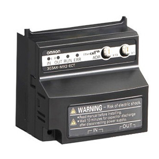
Part Names and Settings for the EtherCAT Communication Unit 2-1-1 Part Names Rotary switches Status indicator for node address (L/A IN, L/A OUT, setting (× 10, × 1) RUN, ERR) Communications connector FG cable (IN, OUT) 2 - 2 EtherCAT Communication Unit USER’S MANUAL (3G3AX-MX2-ECT) -
Page 34: Status Indicator Names
Double flash Application WDT timeout Flickering Boot error PDI WDT timeout Additional Information The timing of each flashing state of indicator is as follows. Flickering Blinking Single flash 1000 Double flash 1000 EtherCAT Communication Unit USER’S MANUAL (3G3AX-MX2-ECT) 2 - 3... -
Page 35: Rotary Switches For Node Address Setting
(× 1) Node address setting (× 10) Note that the node address settings vary as shown below when the Host Controller is made by OMRON and when it is made by other manufacturers. Set value for node address Set value for rotary switch... -
Page 36: Communications Connector
Receive data + Not used Not used Receive data RD Receive data Not used Not used Hood Frame ground EtherCAT Communication Unit USER’S MANUAL (3G3AX-MX2-ECT) 2 - 5... -
Page 37: Recommended Products
If an Ethernet cable of category 5 or higher is used, communications will be possible even if the cable is not shielded. However, we recommend a cable with double, aluminum tape and braided shielding to ensure sufficient noise immunity. 2 - 6 EtherCAT Communication Unit USER’S MANUAL (3G3AX-MX2-ECT) -
Page 38: Connection Between Communications Cables And Connectors
There are 2 types of wiring standards for Ethernet cables: "T568A" and "T568B." The figure above shows a wiring method conforming to the standard "T568A," but a wiring method conforming to the standard "T568B" can also be used. EtherCAT Communication Unit USER’S MANUAL (3G3AX-MX2-ECT) 2 - 7... -
Page 39: Basic Usage Procedures And Configuration Example
Ref section 2-8-2. Checking Master Unit Ref section 2-7-3. Ref section 2-8-3. Ref section 2-7-4. Ref section 2-8-4. Checking Inverter and EtherCAT Communications Unit Ref section 2-7-5. Ref section 2-8-5. Checking operation 2 - 8 EtherCAT Communication Unit USER’S MANUAL (3G3AX-MX2-ECT) -
Page 40: System Configuration Example
CJ1W-NCx82 Master Master Unit : CJ2-series PLC + CJ1W-NCx82 Slave Unit ( 2) : 3G3MX2-A2001 + 3G3AX-MX2-ECT ( 2 sets) (Notes) This Communication Unit can be used with all the capacities in the SYSDRIVE MX2 series. Used for data setting •... - Page 41 NJ501-1x00 Master Master Unit : Machine Automation Controller NJ501-1x00 series Slave Unit ( 2) : 3G3MX2-A2001 + 3G3AX-MX2-ECT ( 2 sets) (Notes) This Communication Unit can be used with all the capacities in the SYSDRIVE MX2 series. Used for data setting •...
-
Page 42: Cj1W-Ncx82 Master Setting
Perform the settings for the CJ1W-NCx82 Master Unit. For the setting method of each component, refer to the manual for the Master Unit. For the setting tool, use CX-Programmer Ver. 9.2 or later. EtherCAT Communication Unit USER’S MANUAL (3G3AX-MX2-ECT) 2 - 11... -
Page 43: Nj501-1X00 Master Setting
NJ-series CPU Unit Software User’s Manual (Cat No.W501). 2-4-2 NJ501-1x00 Setting Set the NJ501-1x00 Master. For the setting method for each part, refer to NJ-series CPU Unit Software User’s Manual (Cat No.W501). 2 - 12 EtherCAT Communication Unit USER’S MANUAL (3G3AX-MX2-ECT) -
Page 44: Mounting And Wiring For The Ethercat Communication Unit
Removing the optional board cover from the inverter front panel Loosen the mounting screw ( 1) from the optional board cover of the inverter front panel. Remove the optional board cover. EtherCAT Communication Unit USER’S MANUAL (3G3AX-MX2-ECT) 2 - 13... - Page 45 EtherCAT Communication Unit. Tighten the mounting screw of the EtherCAT Communication Unit. Tighten the bottom right screw of the EtherCAT Communication Unit with the specified torque (46 N•cm, 4.7 kgf•cm). 2 - 14 EtherCAT Communication Unit USER’S MANUAL (3G3AX-MX2-ECT)
-
Page 46: Wiring The Ethercat Communication Unit
Connect both ends of the shielded wires of the cable to the hoods. For details on preparing the cables, refer to 2-1-6 Connection between Communications Cables and Connectors on page 2-7. EtherCAT Communication Unit USER’S MANUAL (3G3AX-MX2-ECT) 2 - 15... - Page 47 • Do not install the cables near devices generating noise. • Do not install the cables in high-temperature and high-humidity environments. • Use the cables in locations without powder dust or oil mist. 2 - 16 EtherCAT Communication Unit USER’S MANUAL (3G3AX-MX2-ECT)
-
Page 48: Wiring Conforming To Emc Directives
RESET FG cable Communications cable Communications cable (IN) (OUT) (Notes) The overall mounting appearance varies depending on the inverter capacity. Do not squeeze the FG cable into the EtherCAT Communication Unit. EtherCAT Communication Unit USER’S MANUAL (3G3AX-MX2-ECT) 2 - 17... -
Page 49: Node Address Settings For The Ethercat Communication Unit
(Notes) If a slave other than this product is also connected to the same network, set the unit by referring to its User Manual. In such cases, check that the node addresses do not overlap with other units. 2 - 18 EtherCAT Communication Unit USER’S MANUAL (3G3AX-MX2-ECT) -
Page 50: Sysdrive Mx2 Series Settings
Parameter No. Function name Data Default value C102 Reset Selection 03 (Trip reset only) 00 (Trip reset at power-ON) * If parameter C102 is not displayed, first set parameter b037 to 01. EtherCAT Communication Unit USER’S MANUAL (3G3AX-MX2-ECT) 2 - 19... -
Page 51: Communication Starting And Operation Checking With Cj1W-Ncx82 Master
The indicators of the CJ1W-NCx82 make it easy to check the changes in status. 7-segment ECAT ECAT display Initial processing Flashing Normal operation “00” Flashing For details, refer to Position Control Units CJ1W-NC281/NC481/NC881/NCF81/NC482/NC882 OPERATION MANUAL (Cat No.W487). 2 - 20 EtherCAT Communication Unit USER’S MANUAL (3G3AX-MX2-ECT) -
Page 52: Checking The Inverter And Ethercat Communication Unit
* If three or more units are connected, the status LEDs behave in the same way as the LEDs on the first unit, except for the last unit. L/A OUT on the last unit is always unlit. 2-7-5 Checking the Operation Execute the PLC control program and check that the operation is normal. EtherCAT Communication Unit USER’S MANUAL (3G3AX-MX2-ECT) 2 - 21... -
Page 53: Communication Starting And Operation Checking With Nj501-1X00 Master
Firstly, enter the network settings. How to set the network is explained below by taking the "MX2-ECT sample" project as an example. Starting the Sysmac Studio <Project Window> Click the New Project Button, enter MX2-ECT sample under the Project name, and then click the Create Button. 2 - 22 EtherCAT Communication Unit USER’S MANUAL (3G3AX-MX2-ECT) - Page 54 When a group of items that can be registered as an EtherCAT slave appears on the right side of the pane, select Frequency Inverter. From the slave list on the right side of the pane, drag and drop 3G3AX-MX2-ECT onto Master at the center of the pane, and the Unit will be registered as an EtherCAT slave.
- Page 55 If you want to assign a variable to each object that controls the inverter and use the assigned variables in the control algorithms, define the variables on this pane. <I/O Map Pane> 2 - 24 EtherCAT Communication Unit USER’S MANUAL (3G3AX-MX2-ECT)
- Page 56 Click Transfer To Controller to transfer the program data. When the transfer is completed successfully, the RUN LED indicator on the inverter turns ON. The inverter is now ready. <Synchronization Pane> EtherCAT Communication Unit USER’S MANUAL (3G3AX-MX2-ECT) 2 - 25...
-
Page 57: Checking The Nj501-1X00 Master
L/A OUT on the last unit is always unlit. 2-8-5 Checking the Operation Execute the NJ501-1x00 Master control program and check that the operation is normal. 2 - 26 EtherCAT Communication Unit USER’S MANUAL (3G3AX-MX2-ECT) - Page 58 3-6 Sysmac Device Functions ........3-8 EtherCAT Communication Unit USER’S MANUAL (3G3AX-MX2-ECT)
-
Page 59: Structure Of Canopen Over Ethercat
PDO. The contents of the process data are defined by the PDO mapping. Process data communications cyclically reads and writes the PDO. Mailbox communications (SDO) uses asynchronous message communications where all objects in the object dictionary can be read and written. 3 - 2 EtherCAT Communication Unit USER’S MANUAL (3G3AX-MX2-ECT) -
Page 60: Communications Status Transitions
Operational (Op) Supported Supported Supported This is a normal operating state. Cyclic communications can be used to control the motor. EtherCAT Communication Unit USER’S MANUAL (3G3AX-MX2-ECT) 3 - 3... -
Page 61: Process Data Objects (Pdo)
Object D 6TTT hex TT hex Object A 6UUU hex UU hex Object B 6VVV hex VV hex Object C 6YYY hex YY hex Object D 6ZZZ hex ZZ hex Object E 3 - 4 EtherCAT Communication Unit USER’S MANUAL (3G3AX-MX2-ECT) -
Page 62: Sync Manager Pdo Assignment Settings
5110 hex Output frequency monitor PDO mapping for speed control (CiA402 profile) RxPDO 6040 hex Controlword (1700 hex) 6042 hex vl target velocity TxPDO 6041 hex Statusword (1B00 hex) 6043 hex vl velocity demand EtherCAT Communication Unit USER’S MANUAL (3G3AX-MX2-ECT) 3 - 5... -
Page 63: Service Data Objects (Sdo)
Data cannot be transferred or stored to the application because of local control 08000022 hex Data cannot be transferred or stored to the application because of the present device state 08000023 hex Object dictionary dynamic generation fails or no object dictionary is present 3 - 6 EtherCAT Communication Unit USER’S MANUAL (3G3AX-MX2-ECT) -
Page 64: Emergency Messages
(Command) or 6040 hex (Controlword). FF01 hex A trip occurred for the inverter Eliminate the cause and turn on the bit 7: Fault reset of 5000 hex (Command) or 6040 hex (Controlword). EtherCAT Communication Unit USER’S MANUAL (3G3AX-MX2-ECT) 3 - 7... -
Page 65: Sysmac Device Functions
The following explains the functions available when this product is combined with the Machine Automation Controller including NJ Series or automation software. The EtherCAT Communication Unit 3G3AX-MX2-ECT is a Sysmac device that, if the unit version is 1.1 or later, supports Sysmac device functions. - Page 66 If the specified criteria cannot be met, a Network Configuration Verification Error will occur. Additional Information Since replacement of slave device can be detected, all slave parameters will be set without fail. EtherCAT Communication Unit USER’S MANUAL (3G3AX-MX2-ECT) 3 - 9...
- Page 67 With Sysmac device EtherCAT slaves, SII information is checked on the slave side. If the slave cannot operated based on the SII information written, a SII verification error will occur. If the error still occurs after turning the power OFF and then ON again, contact your OMRON sales representative.
- Page 68 Restrictions ........... 4-16 4-6 Trial operation via EtherCAT Communication Unit ....4-17 EtherCAT Communication Unit USER’S MANUAL (3G3AX-MX2-ECT) 4 - 1...
-
Page 69: Outline
These functions are limited depending on the combination with the used Master Unit. Type Details Allocation when using CJ1W-NCx82 The fixed allocation when connected with OMRON's CJ1W-NCx82. Independent profile OMRON's independently-developed function object. Enables easy control of the inverter. CiA402 drive profile A function object that conforms to the CiA402 drive profile. - Page 70 Sync Manager PDO assignment Details 1C12 hex Allocate RxPDO (master to slave). Up to 5 RxPDOs can be allocated. 1C13 hex Allocate TxPDO (slave to master). Up to 5 TxPDOs can be allocated. EtherCAT Communication Unit USER’S MANUAL (3G3AX-MX2-ECT) 4 - 3...
-
Page 71: Control With The Position Control Unit
4 Inverter Control Control with the Position Control Unit This section describes how to connect the OMRON CJ1W-NCx82 and the EtherCAT Communication Unit to control the inverter. 4-2-1 Inverter Setting Set the inverter parameters as follows. Parameter Description A001 Frequency Reference Selection 1... -
Page 72: Control Method
Specify the value of inverter parameter P060: Multi-step position command 0. Values outside the range are not applied and operation is performed with the previous value. Setting range: Position range setting (reverse side) to position range setting (forward side) EtherCAT Communication Unit USER’S MANUAL (3G3AX-MX2-ECT) 4 - 5... - Page 73 0: OFF 1: ON Multi-function output P2 Multi-function relay output (Reserved) The reserved area. Set 0. * Use by assigning a function to the multi-function output with the inverter parameters. 4 - 6 EtherCAT Communication Unit USER’S MANUAL (3G3AX-MX2-ECT)
-
Page 74: Sample Program
Word Address Meaning CIO 3900 Command Bit 0: During forward operation Bit 1: During reverse operation Bit 3: Fault m + 1 CIO 3901 Output frequency monitor (increments of 0.01 Hz) EtherCAT Communication Unit USER’S MANUAL (3G3AX-MX2-ECT) 4 - 7... - Page 75 During reverse operation (word m bit 1) The frequency reference data in D00000 Frequency reference (word n + 1) is forwarded to word n + 1. Fault occurred (30.00) Fault reset (0.03) 4 - 8 EtherCAT Communication Unit USER’S MANUAL (3G3AX-MX2-ECT)
- Page 76 (6) When "Fault (word m bit 3)" of the remote I/O input relay area turns ON, "Fault occurred" turns ON. (7) When the "Fault reset" contact is turned ON, "Fault reset (word n bit 7)" of the remote I/O output relay area turns ON and the fault is cancelled. EtherCAT Communication Unit USER’S MANUAL (3G3AX-MX2-ECT) 4 - 9...
-
Page 77: Control With The Independent Profile
4 Inverter Control Control with the Independent Profile This section describes how to use the OMRON profile to control the inverter. 4-3-1 Inverter Setting The inverter parameters must be set to match the profile. With the independent profile, set as follows. - Page 78 1: Error (Cannot update data for the inverter. To restore, turn the power supply OFF and then ON again.) Reserved Set 0. Output frequency monitor Name Meaning Output frequency monitor Displays the output frequency in increments of 0.01 Hz. EtherCAT Communication Unit USER’S MANUAL (3G3AX-MX2-ECT) 4 - 11...
-
Page 79: Control With The Cia402 Profile
IO format Control information (master to slave) Word Meaning Controlword n + 1 vl target velocity Status information (slave to master) Word Meaning Statusword m + 1 vl velocity demand 4 - 12 EtherCAT Communication Unit USER’S MANUAL (3G3AX-MX2-ECT) - Page 80 1: Control from Controlword is enabled. Reserved Not used. vl velocity demand Name Meaning vl velocity demand Displays the operation speed in rpm. The operation direction is expressed with a symbol (/+). EtherCAT Communication Unit USER’S MANUAL (3G3AX-MX2-ECT) 4 - 13...
-
Page 81: Control With The Pdo Free Format
Control with the PDO Free Format Objects can be freely allocated to PDOs to create an independent profile. If you use in combination with the OMRON independent profile or the CiA402 drive profile, you can perform advanced control and monitoring. -
Page 82: Objects Allocation In Sysmac Studio
In Sysmac Studio, you can edit the PDO map settings for each slave. Click Edit PDO Map Settings in the Configurations and Setup of the EtherCAT slave to open the Edit PDO Map Settings pane. EtherCAT Communication Unit USER’S MANUAL (3G3AX-MX2-ECT) 4 - 15... -
Page 83: Restrictions
• The greater the number of RxPDOs or TxPDOs is, the longer the data updating cycle becomes. Normally the data is updated every 4 ms, but it can increase to every 6 ms depending on the number. 4 - 16 EtherCAT Communication Unit USER’S MANUAL (3G3AX-MX2-ECT) -
Page 84: Trial Operation Via Ethercat Communication Unit
Select the Test Operation function. Set a desired frequency, acceleration time and deceleration time, and then select Forward or Reverse and run the motor. The motor will keep running until Stop is selected. EtherCAT Communication Unit USER’S MANUAL (3G3AX-MX2-ECT) 4 - 17... - Page 85 4 Inverter Control 4 - 18 EtherCAT Communication Unit USER’S MANUAL (3G3AX-MX2-ECT)
- Page 86 Drive Profile Objects ..........5-22 EtherCAT Communication Unit USER’S MANUAL (3G3AX-MX2-ECT)
-
Page 87: Inverter State Control
8: Shut down 13: Error occurs enabled 9: Disable Voltage (Notes) The Quick stop active state is not supported. If Quick stop is enabled in the Operation enable state, transition 9 is executed. 5 - 2 EtherCAT Communication Unit USER’S MANUAL (3G3AX-MX2-ECT) -
Page 88: State Descriptions
(Notes) sod = Switch on disabled, qs = Quick stop, ve = Voltage enabled, f = Fault, oe = Operation enabled, so = Switched on, rtso = Ready to switch on EtherCAT Communication Unit USER’S MANUAL (3G3AX-MX2-ECT) 5 - 3... -
Page 89: Modes Of Operation
The operation mode is set in Modes of operation (6060 hex). In addition, the operation mode is given in Modes of operation display (6061 hex). The operation modes supported by the inverter can be checked in Supported drive modes (6502 hex). 5 - 4 EtherCAT Communication Unit USER’S MANUAL (3G3AX-MX2-ECT) -
Page 90: Velocity Mode
Sets the deceleration time. 6041 hex Statusword Sets the status of the inverter. 6043 hex vl velocity demand Gives the command speed. 6044 hex vl velocity actual value Gives the output speed. EtherCAT Communication Unit USER’S MANUAL (3G3AX-MX2-ECT) 5 - 5... -
Page 91: Object Dictionary
Definitions of variables that can be used by all servers for designated communications. 2000 to 2FFF hex Manufacturer Specific area 1 Variables with common definitions for all OMRON products. 3000 to 5FFF hex Manufacturer Specific area 2 Variables with definitions for this unit. (Inverter parameters,... - Page 92 : Indicates whether the object is read only, or read and write. RO: Read only. WO: Write only. RW: Read and write. • PDO map : Indicates the PDO mapping attribute. EtherCAT Communication Unit USER’S MANUAL (3G3AX-MX2-ECT) 5 - 7...
-
Page 93: Coe Communications Area
Default setting: Size: 20 bytes (VS) Access: RO PDO map: Not possible *1 The version number is saved in “v*.**”. • Gives the Manufacturer software version of the EtherCAT Communication Unit. 5 - 8 EtherCAT Communication Unit USER’S MANUAL (3G3AX-MX2-ECT) - Page 94 • Writing to the EEPROM may take up to 3 seconds. (This is when all objects are changed.) • There is a limit to the number of times you can write to the EEPROM. EtherCAT Communication Unit USER’S MANUAL (3G3AX-MX2-ECT) 5 - 9...
- Page 95 Diagnosis messages 1 to 8 in ascending order. When the 9th error is reached, it is saved as Diagnosis message 1 and the sequence starts again. • The diagnosis history is retained even when the power supply is turned OFF. 5 - 10 EtherCAT Communication Unit USER’S MANUAL (3G3AX-MX2-ECT)
-
Page 96: Pdo Mapping Objects
Size: 4 bytes (U32) Access: RO PDO map: Not possible • The PDO mapping when Velocity mode is used. • The following objects are mapped. • Controlword (6040 hex), vl target velocity (6042 hex) EtherCAT Communication Unit USER’S MANUAL (3G3AX-MX2-ECT) 5 - 11... - Page 97 Size: 4 bytes (U32) Access: RO PDO map: Not possible • The PDO mapping when Velocity mode is used. • The following objects are mapped. • Statusword (6041 hex), vl velocity demand (6043 hex) 5 - 12 EtherCAT Communication Unit USER’S MANUAL (3G3AX-MX2-ECT)
-
Page 98: Sync Manager Communication Objects
: Mailbox reception (master to slave) • SM1 : Mailbox send (slave to master) • SM2 : Process data output (master to slave) • SM3 : Process data input (slave to master) EtherCAT Communication Unit USER’S MANUAL (3G3AX-MX2-ECT) 5 - 13... - Page 99 • The receive PDOs used by this Sync Manager are given. • Up to 5 PDOs can be assigned. • An object from 5000 to 5999 cannot be allocated at the same time as an object from 6000 to 6999. 5 - 14 EtherCAT Communication Unit USER’S MANUAL (3G3AX-MX2-ECT)
- Page 100 • Synchronization type (1C33 to 01 hex) indicates the Synchronization mode of Sync Manager 2. • 0000 hex: Free Run mode • Synchronization types supported (1C33 to 04 hex) indicates the types of synchronization supported. • 0001 hex: Free Run mode EtherCAT Communication Unit USER’S MANUAL (3G3AX-MX2-ECT) 5 - 15...
-
Page 101: Manufacturer Specific Area
• This function can be executed by writing 6C636C65 hex using SDO mailbox communications. • In the following cases, an abort code is returned. • Writing with CompleteAccess • Writing a value other than 6C636C65 hex 5 - 16 EtherCAT Communication Unit USER’S MANUAL (3G3AX-MX2-ECT) -
Page 102: Inverter Parameter Objects
* PDO mapping can only be performed for parameters that exist in the inverter. Only parameters that can be set during operation can be mapped to RxPDO. 3001 to 3101 hex Inverter parameter objects 2 to 258 (16-bit access) Same format as 3000 hex, inverter registers 00FD to FFFB hex EtherCAT Communication Unit USER’S MANUAL (3G3AX-MX2-ECT) 5 - 17... - Page 103 * PDO mapping can only be performed for parameters that exist in the inverter. Only parameters that can be set during operation can be mapped to RxPDO. 4001 to 4101 hex Inverter parameter objects 2 to 258 (32-bit access) Same format as 3000 hex, inverter registers 00FD to FFFB hex 5 - 18 EtherCAT Communication Unit USER’S MANUAL (3G3AX-MX2-ECT)
-
Page 104: Independent Profile Objects
* PDO mapping can only be performed for parameters that exist in the inverter. Only parameters that can be set during operation can be mapped to RxPDO. 5-6-3 Independent Profile Objects This section explains about OMRON's independent profile objects. 5000 hex Command Unit: ... - Page 105 PDO mapping. Messages are saved in sequence from 1 to 6, and no more are saved. The history is cleared when the power supply is turned OFF or the state transitions from initialization (Init) to pre-operational (Pre-Op) is made. 5 - 20 EtherCAT Communication Unit USER’S MANUAL (3G3AX-MX2-ECT)
- Page 106 Buffer mode is incorrect 8000 hex Resource depletion 8001 hex Internal inconsistency 8002 hex Other error FFFF hex No error For details, refer to Chapter 6 Handling of Errors and Maintenance. EtherCAT Communication Unit USER’S MANUAL (3G3AX-MX2-ECT) 5 - 21...
-
Page 107: Device Profile Area
1: Warning occurred for the unit or inverter. Reserved Not used. Remote 0: Control from Controlword is disabled. 1: Indicates that control is being performed by Controlword. 10 to 15 Reserved Not used. 5 - 22 EtherCAT Communication Unit USER’S MANUAL (3G3AX-MX2-ECT) - Page 108 • To read the Speed (6048 to 01 hex), read the inverter parameter A004: Maximum Frequency. • To read and write the Time (6048 to 02 hex), read and write the inverter parameter F002: Acceleration Time Setting. EtherCAT Communication Unit USER’S MANUAL (3G3AX-MX2-ECT) 5 - 23...
- Page 109 Size: 2 bytes (Int16) Access: RW PDO map: Not possible • This object sets the behavior when an error occurs. • Explanation of set values Set value Stop method Deceleration stop 5 - 24 EtherCAT Communication Unit USER’S MANUAL (3G3AX-MX2-ECT)
- Page 110 0: Not supported csp (Cyclic Sync Position mode) 0: Not supported csv (Cyclic Sync Velocity mode) 0: Not supported cst (Cyclic Sync Torque mode) 0: Not supported 10 to 31 Reserved EtherCAT Communication Unit USER’S MANUAL (3G3AX-MX2-ECT) 5 - 25...
- Page 111 5 CiA402 Drive Profile 5 - 26 EtherCAT Communication Unit USER’S MANUAL (3G3AX-MX2-ECT)
- Page 112 6-4 Inverter Errors ..........6-10 EtherCAT Communication Unit USER’S MANUAL (3G3AX-MX2-ECT)
-
Page 113: Communication Line Errors
• Check that the communications cable is wired correctly. • Check that the Master Unit is operating correctly. If using an OMRON Master Unit, check the Master Unit mode and the node address-setting rotary switches of the Communication Unit. - Page 114 Pre-operational An instruction to transition to state pre-operational state was generated by the master. Init state An instruction to transition to init state was generated by the master. EtherCAT Communication Unit USER’S MANUAL (3G3AX-MX2-ECT) 6 - 3...
-
Page 115: Troubleshooting
L/A IN and L/A OUT indicators remain Slaves are not connected to the network. • Check that the Master Unit is operating correctly. If using an OMRON Master Unit, check the Master Unit mode and the slave node addresses. • If using a Master Unit from another manufacturer, refer to the user's manual for that master. -
Page 116: Message Errors
Data cannot be transferred or stored to the application because of local control 08000022 hex Data cannot be transferred or stored to the application because of the present device state 08000023 hex Object dictionary dynamic generation fails or no object dictionary is present EtherCAT Communication Unit USER’S MANUAL (3G3AX-MX2-ECT) 6 - 5... -
Page 117: Application Errors
FF01 hex A trip occurred for the inverter Eliminate the cause and set bit 7: Fault reset of Command (5000 hex) or bit 7: Fault reset of Controlword (6040 hex) to 6 - 6 EtherCAT Communication Unit USER’S MANUAL (3G3AX-MX2-ECT) -
Page 118: List Of Cause Codes For Pdo Mapping Errors
The objects allocated to RxPDO are different, but the same function, registers are overlapping) such as a start command or speed reference, is allocated more than once. Change the PDO mapping. EtherCAT Communication Unit USER’S MANUAL (3G3AX-MX2-ECT) 6 - 7... - Page 119 8000 to 8002 hex Other error An error other than those above occurred. Turn the power supply OFF and ON again. If the problem persists, replace the unit. FFFF hex No error 6 - 8 EtherCAT Communication Unit USER’S MANUAL (3G3AX-MX2-ECT)
-
Page 120: Al Status Code List
An invalid RxPDO is set. Correct the RxPDO mapping setting. For the detailed cause, check the contents of object 5200 hex. 0028 hex SM event mode setting error Set to an unsupported SM event mode. Set a correct value. EtherCAT Communication Unit USER’S MANUAL (3G3AX-MX2-ECT) 6 - 9... -
Page 121: Inverter Errors
PCB. The optional board is faulty. If they are fitted together correctly, the optional PCB may be faulty. Replace the optional board. 6 - 10 EtherCAT Communication Unit USER’S MANUAL (3G3AX-MX2-ECT) - Page 122 A-5 Sysmac Error Status Codes ........A-36 EtherCAT Communication Unit USER’S MANUAL (3G3AX-MX2-ECT)
-
Page 123: A-1 Specifications
20% to 90% RH (with no condensation) Vibration 5.9 m/s (0.6 G), 10 to 55 Hz Application environment At a maximum altitude of 1,000 m; indoors (without corrosive gases or dust) Weight 100 g max. EtherCAT Communication Unit USER’S MANUAL (3G3AX-MX2-ECT) -
Page 124: A-1-3 Ethercat Communications Specifications
Emergency messages, SDO requests, SDO responses, and SDO information Distributed clock FreeRun mode (asynchronous) L/A IN (Link/Activity IN) 1 LED display L/A OUT (Link/Activity OUT) 1 RUN 1 ERR 1 CiA402 drive profile Velocity mode EtherCAT Communication Unit USER’S MANUAL (3G3AX-MX2-ECT) -
Page 125: A-2 Communications Response Time
4 ms or 6 ms Varies depending on the number of allocated PDOs * Due to the characteristics of EtherCAT, the result will become the same with any node as long as the communication cycle is the same. EtherCAT Communication Unit USER’S MANUAL (3G3AX-MX2-ECT) -
Page 126: A-3 Object List
4 bytes (U32) (1st Output Object to be mapped) possible 2nd object 00000000 hex 4 bytes (U32) possible (2nd Output Object to be mapped) *1 "V*.**" which shows the hardware version is saved. EtherCAT Communication Unit USER’S MANUAL (3G3AX-MX2-ECT) - Page 127 Number of assigned PDOs 00 hex 1 byte (U8) possible 1C11 hex Sync Manager 1 PDO assignment Number of assigned PDOs 00 hex 1 byte (U8) possible EtherCAT Communication Unit USER’S MANUAL (3G3AX-MX2-ECT)
- Page 128 FFFF hex 5010 hex Frequency reference 0000 to 0.01 Hz 0000 hex 2 bytes (U16) Possible FFFF hex (0.1 Hz) 5100 hex Status 0000 to 0000 hex 2 bytes (U16) Possible FFFF hex (TxPDO) EtherCAT Communication Unit USER’S MANUAL (3G3AX-MX2-ECT)
- Page 129 1 byte (INT8) Possible 6061 hex Modes of operation display 0 to 10 02 hex 1 byte (INT8) Possible (TxPDO) 6502 hex Supported drive modes 00000002 hex 4 bytes (U32) possible EtherCAT Communication Unit USER’S MANUAL (3G3AX-MX2-ECT)
-
Page 130: A-4 Inverter Parameter List
Fault Monitor 1 Total RUN time at the time of 1 [h] Possible RUN Time tripping (TxPDO) 4000 001A Fault Monitor 1 Power ON time at the time of 1 [h] Possible ON Time tripping (TxPDO) EtherCAT Communication Unit USER’S MANUAL (3G3AX-MX2-ECT) - Page 131 Total RUN time at the time of 1 [h] Possible RUN Time tripping (TxPDO) 4000 0042 hex Fault Monitor 5 Power ON time at the time of 1 [h] Possible ON Time tripping (TxPDO) A-10 EtherCAT Communication Unit USER’S MANUAL (3G3AX-MX2-ECT)
- Page 132 0: Motor parameter recalculation 1: Set value storage in EEPROM possible Other: Motor parameter recalculation and EEPROM 3009 0902 hex EEPROM Write Mode 0: Write disabled Selection 1: Write enabled possible EtherCAT Communication Unit USER’S MANUAL (3G3AX-MX2-ECT) A-11...
- Page 133 Emergency shutoff Overload protection in a low speed range Digital operator connection error Modbus communication (Modbus-RTU) error Internal data error 43 to 45 50 to 69 Encoder disconnection Overspeed Position control range trip A-12 EtherCAT Communication Unit USER’S MANUAL (3G3AX-MX2-ECT)
- Page 134 1038 hex Current position d030 Possible monitor (TxPDO) 3010 1057 hex Inverter Mode Monitor d060 0: I-C (IM heavy load) Possible 1: I-V (IM light load) (TxPDO) 2: H-I (IM power supply harmonics) EtherCAT Communication Unit USER’S MANUAL (3G3AX-MX2-ECT) A-13...
- Page 135 0.01 [Hz] Possible Reference 0 Starting Frequency to Maximum Frequency 1 * After changing the RUN Command Selection 1, provide an interval of at least 40 ms before the RUN command is actually executed. A-14 EtherCAT Communication Unit USER’S MANUAL (3G3AX-MX2-ECT)
- Page 136 A044 00: Constant torque characteristics Possible 01: Reduced torque characteristics (TxPDO) 02: Free V/f setting 03: Sensorless vector control 3012 123F hex Output Voltage Gain 1 A045 20 to 100 1 [%] Possible EtherCAT Communication Unit USER’S MANUAL (3G3AX-MX2-ECT) A-15...
- Page 137 10: Operation function output 3012 1265 hex PID Deviation Reverse A077 00: Disabled Possible Output 01: Enabled (TxPDO) 3012 1266 hex PID Variable Range A078 0 to 1000 0.1 [%] Possible Limit (TxPDO) A-16 EtherCAT Communication Unit USER’S MANUAL (3G3AX-MX2-ECT)
- Page 138 12AF Operation Frequency A141 00: Digital Operator Possible Selection 1 01: Volume (TxPDO) 02: Voltage (FV) input 03: Current (FI) input 04: Modbus communication (Modbus-RTU) 05: Do not set. 07: Pulse train frequency EtherCAT Communication Unit USER’S MANUAL (3G3AX-MX2-ECT) A-17...
- Page 139 (TxPDO) Setting 3013 1309 hex Overvoltage/Overcurrent b008 00: Trip Possible Restart Selection 01: 0 Hz restart (TxPDO) 02: Frequency matching restart 03: Trip after frequency matching deceleration stop 04: Frequency pull-in restart A-18 EtherCAT Communication Unit USER’S MANUAL (3G3AX-MX2-ECT)
- Page 140 03: Data other than b031 and the set frequency cannot be changed. 10: Data can be changed during RUN. 3013 1322 hex Motor Cable Length b033 5 to 20 Possible Code Selection (TxPDO) EtherCAT Communication Unit USER’S MANUAL (3G3AX-MX2-ECT) A-19...
- Page 141 (Lower limit: b064 + b065 2) FI Upper Limit Level 3013 1343 hex Window Comparator b064 0. to 100. 1 [%] Possible (Upper limit: b063 b065 2 FI Lower Limit Level A-20 EtherCAT Communication Unit USER’S MANUAL (3G3AX-MX2-ECT)
- Page 142 (TxPDO) 3013 1369 hex Free V/f Frequency 2 b102 0 to Free V/f Frequency 3 1 [Hz] Possible (TxPDO) 3013 136A Free V/f Voltage 2 b103 0 to 8000 0.1 [V] Possible (TxPDO) EtherCAT Communication Unit USER’S MANUAL (3G3AX-MX2-ECT) A-21...
- Page 143 0 to 30 hex (BCD) (d001 to d030) Possible 3013 13A6 d001/d007 Frequency b163 00: Disabled Possible Setting Mode Selection 01: Enabled 3013 13A7 Initial Screen b164 00: Disabled Possible Automatic Switching 01: Enabled Function A-22 EtherCAT Communication Unit USER’S MANUAL (3G3AX-MX2-ECT)
- Page 144 00: Selection disabled Possible Selection 01: Induction motor (TxPDO) 02: High frequency induction motor 3013 13B7 Perform Initialization/ b180 00: Function disabled Possible Mode Selection 01: Initialization/Mode Selection (TxPDO) Execution Execution EtherCAT Communication Unit USER’S MANUAL (3G3AX-MX2-ECT) A-23...
- Page 145 81: 485 (Start co-inverter (TxPDO) communication) 82: Reserved. 83: HLD (Retain output frequency) 84: ROK (Permission of RUN command) 85: EB (Rotation direction detection (C007 only)) 86: DISP (Display fixed) no: NO (Not assigned) A-24 EtherCAT Communication Unit USER’S MANUAL (3G3AX-MX2-ECT)
- Page 146 54: WCFV (Window comparator FV) 55: WCFI (Window comparator FI) 58: FREF (Frequency command source) 59: REF (RUN command source) 60: SETM (Motor 2 selection) 62: EDM (Safety device monitor) 63: Reserved. no: NO (Not assigned) EtherCAT Communication Unit USER’S MANUAL (3G3AX-MX2-ECT) A-25...
- Page 147 02: Output torque 04: Output voltage 05: Input power 06: Electronic thermal load rate 07: LAD frequency 10: Cooling fin temperature 11: Output torque (signed) 13: Do not set. 16: Do not set. A-26 EtherCAT Communication Unit USER’S MANUAL (3G3AX-MX2-ECT)
- Page 148 3014 144B Communication Speed C071 03 (2,400 bps) Possible Selection 04 (4,800 bps) (TxPDO) 05 (9,600 bps) 06 (19.2 kbps) 07 (38.4 kbps) 08 (57.6 kbps) 09 (76.8 kbps) 10 (115.2 kbps) EtherCAT Communication Unit USER’S MANUAL (3G3AX-MX2-ECT) A-27...
- Page 149 (TxPDO) 3014 1488 hex Output P2 ON Delay C132 0 to 1000 0.1 [s] Possible Time (TxPDO) 3014 1489 hex Output P2 OFF Delay C133 0 to 1000 0.1 [s] Possible Time (TxPDO) A-28 EtherCAT Communication Unit USER’S MANUAL (3G3AX-MX2-ECT)
- Page 150 3015 1504 hex Motor Pole Number 1 H004 00: 2P Possible 01: 4P (TxPDO) 02: 6P 03: 8P 04: 10P 3015 1506 hex Speed Response H005 0 to 1000 1 [%] Possible EtherCAT Communication Unit USER’S MANUAL (3G3AX-MX2-ECT) A-29...
- Page 151 200 to +200 3016 1625 hex Torque Bias Value P037 1 [%] Possible 3016 1626 hex Torque Bias Polarity P038 00: As per sign Possible Selection 01: Depends on the RUN direction (TxPDO) A-30 EtherCAT Communication Unit USER’S MANUAL (3G3AX-MX2-ECT)
- Page 152 Recipient Register of All P142 0000 to FFFF hex Possible Stations in Co-inverter Communication 1 3016 1691 hex Sender Register of All P143 0000 to FFFF hex Possible Stations in Co-inverter Communication 1 EtherCAT Communication Unit USER’S MANUAL (3G3AX-MX2-ECT) A-31...
- Page 153 * Each of the above holding registers (Coil Data 0 to 5) consists of 16 sets of coil data. Since coils are not supported in communication between inverters (only holding registers are supported), use the above holding registers if you want to access the coil. A-32 EtherCAT Communication Unit USER’S MANUAL (3G3AX-MX2-ECT)
- Page 154 Manual Torque Boost A243 0 to 500 0.1 [%] Possible Frequency 2 * If the RUN Command 2 Selection has been changed, wait for at least 40 ms before an actual RUN command is issued. EtherCAT Communication Unit USER’S MANUAL (3G3AX-MX2-ECT) A-33...
- Page 155 Parameter (TxPDO) 3024 2429 hex Overload Warning C241 0 to 2000 0.1 [%] Possible Level 2 3025 2502 hex Motor Parameter 2 H202 00: Standard motor parameter Possible 02: Auto-tuning data (TxPDO) A-34 EtherCAT Communication Unit USER’S MANUAL (3G3AX-MX2-ECT)
- Page 156 (Auto-tuning Data) (TxPDO) 3025 252B Motor 2 Parameter Io H233 1 to 65530 0.01 [A] Possible (Auto-tuning Data) (TxPDO) 4025 252C Motor 2 Parameter J H234 1 to 9999000 0.01 Possible (Auto-tuning Data) (TxPDO) EtherCAT Communication Unit USER’S MANUAL (3G3AX-MX2-ECT) A-35...
-
Page 157: A-5 Sysmac Error Status Codes
• An Inverter trip was detected. detected. 34F00000 hex PDO Setting There is an illegal • The PDO mapping or Sync- Error setting value in the Manager settings are incorrect. PDO mapping. A-36 EtherCAT Communication Unit USER’S MANUAL (3G3AX-MX2-ECT) -
Page 158: A-5-2 Error Descriptions
System: System event log Access: Access event log *4 One of the following: Continues: Execution of the user program will continue. Stops: Execution of the user program stops. Starts: Execution of the user program starts. EtherCAT Communication Unit USER’S MANUAL (3G3AX-MX2-ECT) A-37... - Page 159 The Inverter was initialized or the mode was changed. The EtherCAT Communications Unit Replace the EtherCAT Communica- None for the Inverter failed. tions Unit for the Inverter. Attached None information Precautions/ None Remarks A-38 EtherCAT Communication Unit USER’S MANUAL (3G3AX-MX2-ECT)
- Page 160 Remove the cause of the trip accordingly. Then execute an error reset with slave object 5000 hex or a fault reset with 6040 hex. Attached None information Precautions/ None Remarks EtherCAT Communication Unit USER’S MANUAL (3G3AX-MX2-ECT) A-39...
- Page 161 Read and check the ALStatus code Check that there are no mistakes in settings are incorrect. and the value in 5200 hex. Correct the settings for the PDO mapping and settings. SyncManager. Attached None information Precautions/ None Remarks A-40 EtherCAT Communication Unit USER’S MANUAL (3G3AX-MX2-ECT)
- Page 162 Index EtherCAT Communication Unit USER’S MANUAL (3G3AX-MX2-ECT) Index-1...
- Page 163 Wiring standards ............2-7 Independent profile ............4-10 Independent Profile Objects ........5-19 Inverter Parameter Objects ......... 5-17 Manufacturer Specific Objects ........5-16 Node address ..............2-4 Object Dictionary ............5-6 Object List ..............A-5 Index-2 EtherCAT Communication Unit USER’S MANUAL (3G3AX-MX2-ECT)
- Page 165 The Netherlands IL 60173-5302 U.S.A. Tel: (31)2356-81-300/Fax: (31)2356-81-388 Tel: (1) 847-843-7900/Fax: (1) 847-843-7787 © OMRON Corporation 2010 All Rights Reserved. OMRON (CHINA) CO., LTD. OMRON ASIA PACIFIC PTE. LTD. In the interest of product improvement, Room 2211, Bank of China Tower, No.
- Page 166 Below is a list of articles with direct links to our shop Electric Automation Network where you can see: • Quote per purchase volume in real time. • Online documentation and datasheets of all products. • Estimated delivery time enquiry in real time. •...
Need help?
Do you have a question about the 3G3AX-MX2-ECT and is the answer not in the manual?
Questions and answers