Table of Contents
Advertisement
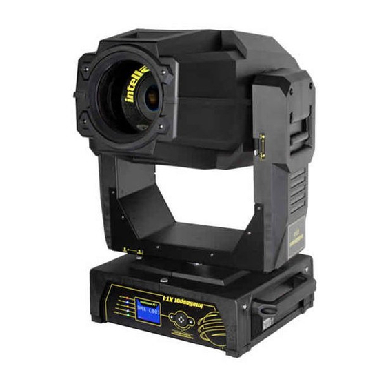
intellaspot™ XT-1
User Manual
© Barco Lighting Systems, 2010, All Rights Reserved
Information and specifications in this document are subject to change without notice. High End Systems, Inc.
assumes no responsibility or liability for any errors or inaccuracies that may appear in this manual.
Trademarks used in this text:
High End Systems, Wholehog, Dataflash, and Lithopatterns are registered trademarks: and intellaspot, Internal
Effects, the High End Systems globe logo, Light Burst, Electronic Dimming, and the Hog logo are trademarks of
Barco Lighting Sytems, High End Systems, Inc. or High End Systems Europe Ltd. Hog is a registered trademark
of Flying Pig Systems. Belden is a registered trademark of Belden, Inc.
Other trademarks and trade names may be used in this document to refer to either the entities claiming the
marks and names or their products. High End Systems disclaims any proprietary interest in trademarks and
trade names owned by others.
tellaspot™ XT-1
in
User Manual
December, 2010
Advertisement
Table of Contents
Troubleshooting

Related Manuals for High End Systems intellaspot XT-1

Summary of Contents for High End Systems intellaspot XT-1
-
Page 1: User Manual
High End Systems, Wholehog, Dataflash, and Lithopatterns are registered trademarks: and intellaspot, Internal Effects, the High End Systems globe logo, Light Burst, Electronic Dimming, and the Hog logo are trademarks of Barco Lighting Sytems, High End Systems, Inc. or High End Systems Europe Ltd. Hog is a registered trademark of Flying Pig Systems. -
Page 2: Contact Information
Contact Information U.S. and the Americas Sales Department Barco Lighting Systems 2105 Gracy Farms Lane Austin, TX 78758 USA voice: 512.836.2242 fax: 512.837.5290 Toll Free: 800.890.8989 Customer Service Barco Lighting Systems 2105 Gracy Farms Lane Austin, TX 78758 USA voice: 800.890.8989 fax: 512.834.9195 toll free: 800.890.8989... -
Page 3: Declaration Of Conformity
ISO/IEC Guide 22 and EN45104 Manufacturer’s name: Barco Lighting Systems Manufacturer’s address: 2105 Gracy Farms Lane Austin, Texas 78758 USA Distributor’s name: High End Systems, Inc. Distributor’s address: 2105 Gracy Farms Lane Austin, Texas 78758 USA Declares that the product: Product Name: intellaspot XT-1... -
Page 4: Important Safety Information
Umständen gegen die diesbezüglichen Sicherheitsnormen verstoßen. Avvertenza Sulla Modifica Del Prodotto I prodotti di High End Systems sono stati progettati e fabbricati per soddisfare i requisiti delle normative di sicurezza statunitensi ed internazionali. Qualsiasi modifica al prodotto potrebbe pregiudicare la sicurezza e rendere il prodotto non conforme agli standard di sicurezza pertinenti. - Page 5 FCC Information This equipment has been tested and found to comply with the limits for a Class A digital device, pursuant to part 15 of the FCC rules. These limits are designed to provide reasonable protection against harmful interference when the equipment is operated in a commercial environment. This equipment generates, uses, and can radiate radio frequency energy and, if not installed and used in accordance with the instruction manual, may cause harmful interference to radio communications.
-
Page 6: Warranty Information
Lamps are covered by the lamp manufacturer’s warranty. A fixture must be returned in its original packaging. Any other parts returned to High End Systems must be packaged in a suitable manner to ensure the protection of such product unit or parts, and such package shall be clearly and prominently marked to indicate that the package contains returned Product units or parts and with an RMA number. - Page 7 Patents This product may use one or more of the following patents: US 4,392,187; US 4,602,321; US 4,688,161; US 4,701,833; US 4,709,311; US 4,779,176; US 4,800,474; US 4,962,687; US 4,972,306; US 4,980,806; US 5,010,459; US 5,031,078; US 5,073,847; US 5,078,039; US 5,186,536; US 5,209,560; US 5,278,742; US 5,282,121;...
- Page 8 viii intellaspot XT-1 User Manual...
- Page 9 Cables and Connectors .................. 5 Related Products and Accessories ..............5 Chapter 2: Setup and Configuration Installation of your intellaspot XT-1 fixture includes mounting, connecting to power and DMX linking and configuration. Unpacking the Fixture ................... 7 Pan and Tilt Locking ..................7 Installing a Power Cord Cap ................
- Page 10 Mounting the Fixture ..................9 Mounting the Fixture Upright ................9 Truss Mounting ..................10 Linking intellaspot XT-1 Fixtures ..............11 Cable Connectors ..................11 Connecting to the Link ................12 Powering On the Fixture ................12 Setting the DMX Start Channel ..............13 Setting a Start Channel in Battery Mode ............
- Page 11 Lamp Life Limit ..................29 Lamp Level ..................... 29 Data Loss Timeout ................... 29 Lamp Strike Mode ..................30 Data Source .................... 30 Fixture Mode Menu ..................31 Crossloading Fixture Software ..............31 Test Options Menu ..................32 Homing the Fixture .................. 32 Lamp State .....................
- Page 12 CMY color, multiple gobo patterns and effects, as well as a variety of Shutter/Lamp functions. This chapter discusses the DMX programming options and describes the parameters in the intellaspot XT-1 DMX protocol. DMX Programming Overview ..............41 Full Speed verses MSpeed Control ..............41 16-bit Functionality ..................
- Page 13 Macro ......................56 Control ......................57 Chapter 5: General Maintenance and Troubleshooting Maintaining and servicing intellaspot XT-1 fixtures includes replacing parts and cleaning the unit. General troubleshooting tips help you identify potential problems. Replacing Parts ................... 60 Replacing Fuses ..................60 Replacing Display Batteries ................
- Page 14 intellaspot XT-1 User Manual...
-
Page 15: This Chapter Describes The Features And Specifications Of The Intellaspot™ Xt
This chapter describes the features and specifications of the intellaspot™ XT-1 fixture along with a list of related products and accessories. The intellaspot XT-1 is a hard-edged moving yoke light featuring smooth CMY color mixing and with variable CTO. A fixed color wheel allows instant color choices via easily exchangeable dichroic filters. -
Page 16: Optics
CHAPTER 1 Product Overview Optics • 5:1 Zoom 11° – 55° • Mechanical and Electronic strobe • Variable soft edge • Fast mechanical iris Effects • CMY color mixing plus variable CTO • Color wheel with replaceable positions • Two seven position plus open rotating gobo wheels •... -
Page 17: Specifications
CHAPTER 1 Product Overview Specifications Mechanical Specifications Dimensions: 381 mm x 551 mm x 909 mm (15 in x 21.7 in x 35.7 in) Shipping Box Dimensions: 597 mm x 610 mm x 1124 mm (23.5 x 24 x 44.25) Fixture weight: 52.17 kg (115 lbs) 66 mm (26.3 in) -
Page 18: Wheel Components
CHAPTER 1 Product Overview Wheel Components Animation Wheel: Diameter: 127.0 mm ± .25 mm (5.0 in ± .10 in) Thickness: 1.75 mm ± .25 mm (.69 in ± .008 in) Maximum image area: 30 mm ± 0.425 mm (1.18 in ± .01 in) Lithopatterns: Diameter: 36.8 mm ±... -
Page 19: Cables And Connectors
2105 Gracy Farms Lane Austin, TX 78758 USA voice:800.890.8989 fax: 512.834.9195 intellaspot XT-1 color wheel dichroic wedge filters toll free: 800.890.8989 Replacement, Module link fuse, 6.3A 250V, SB 90403019EF Replacement display, 2-phase and 3-phase board fuse, 2.5 A, 125 V, Slow... - Page 20 CHAPTER 1 Product Overview intellaspot XT-1 User Manual...
-
Page 21: Unpacking The Fixture
5. Configure the fixture for DMX control using the battery mode or after connecting to power. Unpacking the Fixture The intellaspot XT-1 fixture ships in a box or an optional road case specifically designed to protect the product during transport. When unpacking, inspect the fixture for physical damage to components. High End Systems assumes no responsibility for products that are damaged ®... -
Page 22: Installing A Power Cord Cap
Setup and Configuration Installing a Power Cord Cap The custom power cord for intellaspot XT-1 fixtures ships without a power cord cap. Use the information in this section to install the correct power cord cap for your location. Because of the variety of power cord caps used worldwide, High End Systems, Inc. cannot make specific recommendations for the power cord cap. -
Page 23: Mounting The Fixture
1. Place the fixture on a sturdy, stable non-flammable surface that will support more than the 52.2 kg (115 lb) weight of the intellaspot XT-1 fixture. If the surface is above floor height, use safety cables to secure the fixture to the surface. -
Page 24: Truss Mounting
• Verify the truss or support will handle the combined weight of all the devices on the truss. Each intellaspot XT-1 fixture weighs 52.2 kg (115 lb). • Always mount an intellaspot XT-1 fixture using the mounting bracket assembly that shipped with your fixture and a safety cable attached to the fixture’s base. -
Page 25: Linking Intellaspot Xt-1 Fixtures
Setup and Configuration Linking intellaspot XT-1 Fixtures The intellaspot XT-1 fixture operates on standard DMX512 link controlled by a DMX console. The number of fixtures on a link will be determined by the combined number of channels required by all the fixtures. An intellaspot XT-1 fixture requires a 39 channel footprint on a standard DMX512 link. -
Page 26: Connecting To The Link
Do not unplug motor harnesses while unit is powered. To power on the intellaspot XT-1 fixture, simply connect it to a 100V-240V AC power source. Once the intellaspot XT-1 fixture is connected to a power source, it automatically begins a homing procedure to verify that fixture components are functioning. -
Page 27: Setting The Dmx Start Channel
Each intellaspot XT-1 fixture requires a block of 39 consecutive channels on a standard DMX512 link. Up to 13 standard intellaspot XT-1 fixtures can be assigned to a single link. For more information on Start Channels, see Determining DMX Start Channel Assignment on page 26. -
Page 28: Setting A Start Channel In Battery Mode
CHAPTER 2 Setup and Configuration Setting a Start Channel in Battery Mode Note: This option only applies when no power is applied to the fixture. 1. Turn on the menu system by pressing and holding Set DMX Start the MENU and ENTER buttons at the same time. The Channel: 001 display will show Set DMX Start Channel: ### ... -
Page 29: Shutting Down The Fixture
This is the only pan position that locks. 2. Gently move the fixture head and yoke to verify that both pan and tilt positions are locked in place. 3. Place the intellaspot XT-1 fixture in the road case as shown for shipping. intellaspot XT-1 User Manual... - Page 30 CHAPTER 2 Setup and Configuration intellaspot XT-1 User Manual...
-
Page 31: Menu System Components
Chapter 3: Menu System This chapter shows you how to access and navigate the onboard Menu system and the options available at each menu level with examples. Menu System Components The front panel on intellaspot fixtures has a full color LCD screen and three navigation buttons to display and operate the onboard menu system. -
Page 32: Navigation Buttons
Press and hold both the Menu and Enter buttons to access the battery mode. Note: The intellaspot XT-1 fixture can sense orientation and automatically inverts the display and button functions when the fixture is mounted upside down. Battery Mode Before applying power, you have the option to address the fixture in battery mode. -
Page 33: Display In Menu Locked Mode
• any errors present Fixture Software Version The software version loaded on the fixture can vary even between units purchased at the same time. The latest software version is always posted on the High End Systems website (www.highend.com/support). DMX Start Channel The DMX Start Channel is the first channel currently assigned to that fixture in its range of channels on a DMX link. -
Page 34: Intellaspot™ Xt-1 Menu Map
CHAPTER 3 Menu System intellaspot™ XT-1 Menu Map Menu Level 2 Level 3 Option/Setting Description/Notes Sets the first value of a unique Set DMX Start DMX ADDRESS 1‐474 39-channel range on DMX link. Channel: ### Indicates factory default change Reset Factory Default Settings: XXXXX Reverts to default setting Restores default Pan and Tilt Disabled Pan/Tilt Swap:... - Page 35 Menu NetWork Safe setting Crossload Uploads fixture software to all Mode Firmware: intellaspot XT-1 fixtures on the link. Home Fixture: Homes all fixture functions Indicates or turns lamp off Lamp State: Indicates or turns lamp on Does nothing when selected Copy Boot:...
- Page 36 Information Static Color Menu Function Static Color DMX Values Position Displays current DMX decimal value of each of the 39 Gobo 1 Function By Parameter channels used by the Gobo 1 Position intellaspot XT-1 fixture Gobo 1 Rotate Function Gobo 1 Rotate Coarse Gobo 1 Rotate Fine Gobo 2 Function Gobo 2 Position Gobo 2 Rotate Function Gobo 2 Rotate Coarse Gobo 2 Rotate ...
- Page 37 Option/Setting Description/Notes Effect Function Effect Rotate Coarse Effect Rotate Fine Animate Function Animate Rotate Soft Edge Focus Function Displays current value of each Focus Coarse of the 39 channels used by the intellaspot XT-1 Focus Fine Zoom Coarse DMX Values By Parameter Zoom Fine Iris Lamp Function Shutter M‐Speed Macro Control Information DMX Breaks Menu DMX Framing Err...
- Page 38 CHAPTER 3 Menu System Menu Level 2 Level 3 Option/Setting Description/Notes Lamp operation time in Lamp Hours: hours:minutes Current number of lamp strikes Lamp Strikes: Default “safe” setting Lamp Hr/Strike Press Enter for 5 seconds to Reset: ### reset fixture hours to 0 Lamp Off Lamp On Current lamp Lamp Status:...
-
Page 39: Menu System Options
CHAPTER 3 Menu System Menu System Options The following sections describe and give examples for selecting and/or setting available fixture configuration options. Address Menu Address is the top level menu selection used to set the fixture’s DMX start channel. You can address the fixture before applying power in the battery mode or in normal mode after you power up the fixture. -
Page 40: Determining Dmx Start Channel Assignment
Channel range is the number of consecutive channels a fixture requires. Each intellaspot XT-1 fixture requires a block of 39 consecutive channels on a 512-Channel DMX link. The Start channel is the first number of a fixture’s channel range. -
Page 41: Set Parameters Menu
This option lets you return all factory options to their default settings or changes the factory options DMX [ ] individually. An intellaspot XT-1 fixture ships with the following factory default settings: Pan Tilt Swap = Tilt Invert = Lamp Life Limit =... -
Page 42: Pan/Tilt Swap
CHAPTER 3 Menu System Pan/Tilt Swap This option swaps the pan motor and tilt motor operation to coordinate movements between fixtures on a link mounted perpendicular to each other. To swap Pan and Tilt: 1. Navigate to and select the Set Parameters Menu (see Set Parameters Menu on page 27). -
Page 43: Lamp Life Limit
CHAPTER 3 Menu System Lamp Life Limit Use this menu option to display the warning message when the current lamp hours reach the Lamp Life Error rated lamp life. When the parameter is Lamp Life Limit enabled, the fixture tracks the number of hours the lamp Lamp Life ... -
Page 44: Lamp Strike Mode
CHAPTER 3 Menu System Lamp Strike Mode This menu option lets you choose when the lamp will strike (turn on). To set the Lamp Strike Mode Lamp Strike 1. Navigate to and select the Set Parameters Menu (see Set Parameters Menu on page 27). Mode: Auto 2. -
Page 45: Fixture Mode Menu
4. Use the up and down arrows on the Center button to scroll to the option and press the Enter button to store. The fixture will upload its software to all other intellaspot XT-1 fixtures on the link. When the crossload has finished successfully, will appear briefly in the Crossloading Complete... -
Page 46: Test Options Menu
TEST icon in the screen banner and the first option of the next menu level. Homing the Fixture The intellaspot XT-1 fixture automatically homes DMX [ ] whenever it is turned on. To manually home the fixture: 1. Unlock the menu system and navigate to the as shown above. -
Page 47: Copying The Boot Code
CHAPTER 3 Menu System Copying the Boot Code When new software is uploaded to intellaspot XT-1 fixtures, it may contain a new boot code which must be copied to each fixture. This is apparent if the fixture displays a error. -
Page 48: Setup Motors
CHAPTER 3 Menu System Setup Motors This option is used when calibrating flag motors in Production Homing, see Production Homing on page 51. To run the motor setup routine: Setup Motors: 1. Navigate to and select the Test Options Menu (see Test Options Menu on page 32). 2. -
Page 49: Information Menu
You will know if the sensor is working properly if the value changes as you move the fixture’s position. Unique Number Each intellaspot XT-1 fixture has a unique number similar to a serial number. To view the fixture’s unique number: Unique Number... -
Page 50: Dmx Values Menu
CHAPTER 3 Menu System DMX Values Menu This menu option lets you view the current DMX value for every channel on the DMX link that includes this fixture. You can view all the DMX values on the link by channel or DMX Values ... -
Page 51: Temperatures Menu
CHAPTER 3 Menu System Temperatures Menu The intellaspot XT-1 fixture contains temperature sensors that track current, maximum and minimum temperatures produced in the unit. Sensors monitor the air Temperatures temperature of the electronics housing and the lamp Menu housing. Initially, the setting for current, maximum and minimum temperatures are equal. -
Page 52: Fan Speed Menu
CHAPTER 3 Menu System Fan Speed Menu The intellaspot XT-1 fixture contains four actively controlled internal fans labeled Topbox 1 (located in the electronics housing) Optics, Head 1 and Head 2. Fan Speed Menu To view the current fan speed: 1. Navigate to and select the Information Menu (see Information Menu on page 35). -
Page 53: Lamp Strikes
CHAPTER 3 Menu System Lamp Strikes Knowing the number of lamp strikes helps you to track lamp life and adjust for color temperature changes over the life of a lamp. To view the total number of lamp strikes: 1. Navigate to and select the (see Information Menu on page 35). -
Page 54: Software Version
Channels Needed This option displays the number of channels this fixture requires based on its configuration. A standard configuration intellaspot XT-1 requires 39 channels. Next DMX Channel Use this option to view the next available DMX Start channel on the link following this fixture and is based on the fixture’s specific configuration. -
Page 55: Dmx Programming Overview
Road Hog lighting consoles; and Hog 3PC software are available from High End Systems to control intellaspot XT-1 fixtures (see Related Products and Accessories on page 5). For information on whether your DMX controller supports intellaspot XT-1 fixtures, contact the controller’s vendor. -
Page 56: Intellaspot Xt-1 Dmx Protocol
All DMX values indicated in the detailed parameter descriptions are in decimal units. Pan and Tilt Parameters The intellaspot XT-1 fixture has a 540° pan range and a 270° tilt range. Two DMX channels provide 16-bit adjustment to a fraction of a degree for pan and tilt position. intellaspot... -
Page 57: Color Parameters
CHAPTER 4 Fixture Programming MSpeed values control the pan and tilt motion for intellaspot XT-1 fixtures by default, see MSpeed (Motor Speed) on page 55. To control the Pan and Tilt parameters with DMX controller crossfading, set Pan/Tilt MSpeed off in the Control parameter (see Control on page 57). -
Page 58: Cyan, Magenta, And Yellow
CHAPTER 4 Fixture Programming Cyan, Magenta, and Yellow These three parameters determine the Cyan, Magenta, and Yellow color wheel position and movement. The Color Function parameter value you choose determines how the individual color mixing wheels can move. Color Function Parameter Cyan, Magenta, and Yellow Parameter Options Setting... -
Page 59: Static Color Function
CHAPTER 4 Fixture Programming Static Color Function Open Blue/White White/Red (White) The Static Color Function parameter determines how the Blue fixed color wheel moves and can be enabled in either full speed (controller crossfading the wheel Amber/Blue Red/Pink positions), or MSpeed (MSpeed control of the wheel motor). -
Page 60: Gobo Wheel Parameters
Fixture Programming Gobo Wheel Parameters An intellaspot XT-1 fixture has two Gobo wheels each with seven rotating lithopatterns™ and effects plus an optional lithopattern for position four on Gobo wheel 1. Each Gobo wheel uses Gobo Function and Gobo Position parameters to control the positioning and rotation of the wheels. -
Page 61: Gobo Function
CHAPTER 4 Fixture Programming Gobo Function The Gobo 1 and Gobo 2 Function parameters determine how a gobo wheel moves. The Gobo Function parameter can be enabled in either full speed, or MSpeed (MSpeed control of the wheel motor). For more information about MSpeed, see MSpeed (Motor Speed) on page 55. Gobo Function Parameter Description... -
Page 62: Gobo Rotate
CHAPTER 4 Fixture Programming Gobo Rotate Two channels for each Gobo Wheel provide 16-bit control for smooth and precise Gobo Rotation. Rotate Coarse and Rotate Fine parameters determine the apertures’ rotation position and speed. Gobo Rotate Gobo Rotate Parameter Options Function Parameter Indexed Rotate the specified indexed aperture to any position... -
Page 63: Effect Parameters
CHAPTER 4 Fixture Programming Effect Parameters The intellaspot XT-1 fixture has separate 4-facet prism that can be placed and rotated in the optical path and used along with gobo patterns and color mixing. Effect Function The Effect Rotate Function parameter determines how the prism effect wheel moves and can be enabled in either full speed (controller crossfading the wheel positions), or MSpeed (MSpeed control of the wheel motor). -
Page 64: Animation Wheel Parameters
The Animation effect wheel is a separate lithopattern wheel providing another effect that can be layered onto the light beam output of an intellaspot XT-1 fixture. Animation Function The Animation Function parameter determine how the animation effect wheel moves and can... -
Page 65: Soft Edge Parameter
CHAPTER 4 Fixture Programming Soft Edge Parameter The Soft Edge parameter settings add a haze or fog effect in increasing/decreasing densities to the projected pattern. The soft edge effect is achieved with a single flag that moves into the optical path. Soft Edge Description Parameter Setting... -
Page 66: Focus Parameters
The Focus Course and Focus Fine parameters focus from in to out, Zoom Parameter The intellaspot XT-1 fixture has a 5:1 zoom ranging from 11° to 55°. The Zoom Coarse and Zoom Fine parameters provide 16-bit continuous control for smooth and precision zoom function from in to out. -
Page 67: Shutter And Lamp Parameters
Shutter/Lamp Function The Lamp Function parameter) modifies the Shutter parameter and Dim parameter functions to enhance and expand the range of effects available on the intellaspot XT-1 fixture including Light Burst™ effects, lightning strikes and Electronic Dimming™ effects. The Light Burst™ effect boosts the Lamp above the 850 Watt level for the specified period of time. - Page 68 CHAPTER 4 Fixture Programming Lamp Function Setting Shutter Parameter Options Close Shutter Periodically strobe the lamp with shutters open boosting the lamp above 850 W Randomly strobe the lamp with shutters open boosting the lamp above 850 W Synchronize random lamp strobing between all intellaspot XT- 1 fixtures controlled by the same DMX console.
-
Page 69: Mspeed (Motor Speed)
CHAPTER 4 Fixture Programming MSpeed (Motor Speed) MSpeed is the time required for a motor to complete movement when changing from one position to another. MSpeed provides a means for all motors to reach their target position at the same time, even though each motor may have different distances to travel. -
Page 70: Macro
Each Internal Effects™ macro modifies a specific set of parameters, while allowing user control of all other parameters in the scene. The four Internal Effects macros available on a standard configuration intellaspot XT-1 fixture are Pan Sweep, Tilt Sweep, Clockwise Circle and Counterclockwise Circle. -
Page 71: Control
CHAPTER 4 Fixture Programming Control The Control parameter allows remote control of Pan and Tilt MSpeed, Display, Homing, Lamp and Shutdown. Note: To access all control settings (except for Pan & Tilt MSpeed Off), first select a control channel value, then set the Shutter channel to “0.” Control Parameter Setting Description Safe... - Page 72 CHAPTER 4 Fixture Programming intellaspot XT-1 User Manual...
-
Page 73: Chapter 5: General Maintenance And Troubleshooting
Maintaining and servicing intellaspot XT-1 fixtures includes replacing parts and cleaning the unit. General troubleshooting tips help you identify potential problems. The intellaspot XT-1 fixture is designed for simple maintenance. Modules are easily removed for repair or custom configurations. The module driver boards are identical and use orientation to differentiate their function for a specific module. -
Page 74: Replacing Parts
CHAPTER 5 General Maintenance and Troubleshooting Replacing Parts WARNING: Disconnect power before servicing. Replace fuses with the specified type and rating only. Equipment surfaces may reach temperatures up to 130° C (266° F). Allow the fixture to cool before handling. Replacing Fuses To replace a fuse: 1. -
Page 75: Replacing Display Batteries
General Maintenance and Troubleshooting Replacing Display Batteries Four AA cell rechargeable batteries power the intellaspot XT-1 LCD display. They are located in a bracket on the back of the display panel. Replace with Sanyo Eneloop, Rayovac Platinum, or comparable precharged rechargeable AA cell 1.2V NiMH batteries. - Page 76 CHAPTER 5 General Maintenance and Troubleshooting To replace the lamp: 1. Disconnect power to the fixture. If the fixture has been operating, wait for the lamp to cool before handling. 2. Put on protective eyewear and gloves. Lamp 3. Using a wide tip, flat head screwdriver, assembly loosen (but do not remove) the two lamp screws...
-
Page 77: Optimizing The Lamp
CHAPTER 5 General Maintenance and Troubleshooting Optimizing the Lamp Optimize the lamp after replacement, or if there is a “hot spot” of brightness anywhere other than the center of the light beam. 1. Orient the fixture so that the beam will project onto a flat, white surface at least 10 feet (3m) away. -
Page 78: Replacing Interchangeable Motor Driver Boards
General Maintenance and Troubleshooting Replacing Interchangeable Motor Driver Boards The intellaspot XT-1 fixture is designed with two basic types of motor driver boards: 1. Interchangeable 2-phase boards drive the motors for each of the user-configured modules, and the Focus/Frost/Zoom functions. -
Page 79: Phase Board Configuration
CHAPTER 5 General Maintenance and Troubleshooting 2-Phase Board Configuration Board 1 MTG2 MTG1 M1 Animation M2 Animation Rotate M3 Prism FX Position Sensor M4 Prism FX Rotate S1 Animation Sensor MTG3 MTG4 S3 Prism FX Position Sensor Board 2 MTG2 M1 Dim 1 MTG1 M2 Cyan... -
Page 80: Phase Board Location And Configuration
CHAPTER 5 General Maintenance and Troubleshooting 3-Phase Board Location and Configuration Two 3-phase boards drive Pan and Tilt motors. They are located on the back of the electronic housing’s display panel. Pan Board MTG1 MTG2 Pan Motor Pan Encoder Lamp Power Supply Pan Sensor Lamp Power Supply Fan Optics Fan... -
Page 81: Replacing A Motor Driver Board
CHAPTER 5 General Maintenance and Troubleshooting Replacing a Motor Driver Board When changing a board, align the screw holes and standoffs to ensure correct orientation in the fixture. To replace a 2-phase driver board: 1. After remove the bezel and electronic housing cover if applicable, Use a 3 mm allen wrench to remove the addressing screws and star washers. -
Page 82: Replacing Static Color Wheel Dichroic Wedges
CHAPTER 5 General Maintenance and Troubleshooting Replacing Static Color Wheel Dichroic Wedges Replace color wedges if they are damaged or broken, to change their order in the wheel, or to install a new or custom color. (See Related Products and Accessories on page 5 for ordering information.) To replace a color wedge: 1. - Page 83 For dichroic wedge specifications, see the intellaspot XT-1 support page at www.highend.com/support/ automated_luminaires/. 10. Slide the module back into the fixture and tighten the thumbscrew screw to secure it.
-
Page 84: Replacing Intellaspot Xt-1 Lithopatterns
General Maintenance and Troubleshooting ® Replacing intellaspot XT-1 Lithopatterns You can use the steps in this section to replace lithopatterns if they are damaged or broken, to change their order in the wheel, to clean them, or to install a new or custom lithopattern or effect. -
Page 85: Replacing The Animation Wheel
CHAPTER 5 General Maintenance and Troubleshooting Replacing the Animation Wheel WARNING! To avoid electrical shock, disconnect power before servicing. Equipment surfaces may reach temperatures up to 130° C (266° F). Allow the fixture to cool before handling. Use these steps to replace the animation wheel if it is broken, or to change to a custom wheel. Note: You can find drawings and specifications for a custom animation wheel on the intellaspot support page at www.highend.com/support/automated_luminaires. -
Page 86: Cleaning The Fixture
Filters Bezel filters are located on the There are five washable inside of each cover over air intakes. filters in intellaspot XT-1 fixtures. Two are behind the intake vents on the electronics housing. Two are located on the inside of one head cover and one on the other head cover. -
Page 87: Troubleshooting
CHAPTER 5 General Maintenance and Troubleshooting Troubleshooting System State LEDs Five labeled LEDs on the display panel indicate the following system activity: Problem Name Color State Description (45 sec On/1.4 sec.Off) Running normal motion-control code Status Green Fixture code not running Lamp is on Lamp is off Lamp... - Page 88 CHAPTER 5 General Maintenance and Troubleshooting Location LED # State Problem? Description Green Board receiving proper voltage Dim green Board not receiving data Board not receiving power HD6 sensor open 3-phase board Green HD6 sensor closed Flashing red Board not receiving data Board not receiving data or power Green Board programmed properly...
-
Page 89: Appendix A: Mspeed Conversion Table
Appendix A: MSpeed Conversion Table The following table lists the MSpeed (motor) movement times and their corresponding DMX controller values. If you have a numeric-type controller, use the Value Decimal (dec.) column. If you have a fader-type controller, use the Value Percentage (%) column. If your controller allows you to program hex values, use the Value (hex) column. - Page 90 Appendix A MSpeed Conversion Table Time Value Value Value Time Value Value Value Time Value Value Value (sec.) (dec.) (hex) (sec.) (dec.) (hex) (sec.) (dec.) (hex) 51.33 102.77 175.24 52.24 104.05 176.92 53.16 105.35 178.61 54.09 106.65 180.30 55.02 107.96 182.01 55.96v 109.28...
-
Page 91: Appendix B: Important Safety Information
Appendix B: Important Safety Information Warning: For Continued Protection Against Fire 1. This equipment is designed for use with specified lamps only. Use of any other type lamp may be hazardous and may void the warranty. 2. Do not mount on a flammable surface. 3. - Page 92 Appendix B Important Safety Information Warning: For Continued Protection Against Injury To Persons 1. Use secondary safety cable when mounting this fixture. 2. Caution: Hot lamp may be an explosion hazard. Do not open for 5 minutes after switching off. Wear eye and hand protection when re-lamping.
-
Page 93: Appendice B: Importantes Informations Sur La Sécurité
Appendix B Important Safety Information Appendice B: Importantes Informations Sur La Sécurité Mise En Garde: Pour Une Protection Permanente Contre Les Incendies 1. Cet appareil est conçu pour l'usage avec les lampes spécifiées seulement. Son utilisation avec tout autre type de lampe peut être dangereuse et annuler la garantie. 2. -
Page 94: Anhang B: Wichtige Hinweise Für Ihre Sicherheit
Appendix B Important Safety Information Anhang B: Wichtige Hinweise Für Ihre Sicherheit Warnung: Zum Schutz Vor Brandgefahr 1. Diese Ausrüstungen sind für Gebrauch mit angegebenen Lampen nur entworfen. Der Gebrauch irgend eines anderen Lampentyps könnte Sie gefährden und Ihre Garantie außer Kraft setzen. -
Page 95: Apéndice B: Información Importante De Seguridad
Appendix B Important Safety Information Apéndice B: Información Importante De Seguridad Advertencia: Para Protección Continua Contra Incendios 1. Este equipo se diseña para el uso con lámparas especificadas sólo. El uso de cualquier otro tipo de lámpara puedá resultar peligroso, y puedá anular la garantía. 2. -
Page 96: Appendice B: Importanti Informazioni Di Sicurezza
Appendix B Important Safety Information Appendice B: Importanti Informazioni Di Sicurezza Avvertenza: Per Prevenire Incendi 1. Quest'apparecchiatura è disegnata per l'uso con le lampade specificate soltanto. L'uso di qualunque altra lampada di tipo può essere pericoloso e può nullo la garanzia. 2. -
Page 97: Vigtig Sikkerhedsinformation
Appendix B Important Safety Information Vigtig Sikkerhedsinformation Advarsel: Beskyttelse mod elektrisk chock. VIGTIGT! LEDEREN MED GUL/GROEN ISOLATION MAA KUN TILSLUTTES KLEMME MAERKET ELLER intellaspot XT-1 User Manual... - Page 98 Appendix B Important Safety Information intellaspot XT-1 User Manual...
Need help?
Do you have a question about the intellaspot XT-1 and is the answer not in the manual?
Questions and answers