Table of Contents
Advertisement
Quick Links
Digital Energy
Multilin
Software Revision: 5.0x
Manual P/N: 1601-0122-A8
Manual Order Code: GEK-106474G
Copyright © 2009 GE Multilin
GE Multilin
215 Anderson Avenue, Markham, Ontario
Canada L6E 1B3
Tel: (905) 294-6222 Fax: (905) 201-2098
Internet:
http://www.GEmultilin.com
*1601-0122-A8*
469 Motor Management
Relay
Instruction Manual
GE Multilin's Quality Management
System is registered to
ISO9001:2000
QMI # 005094
UL # A3775
Advertisement
Table of Contents

Summary of Contents for GE Multilin 469
- Page 1 Multilin 469 Motor Management Relay Instruction Manual Software Revision: 5.0x Manual P/N: 1601-0122-A8 Manual Order Code: GEK-106474G Copyright © 2009 GE Multilin GE Multilin 215 Anderson Avenue, Markham, Ontario Canada L6E 1B3 Tel: (905) 294-6222 Fax: (905) 201-2098 Internet: http://www.GEmultilin.com...
- Page 2 The contents of this manual are the property of GE Multilin Inc. This documentation is furnished on license and may not be reproduced in whole or in part without the permission of GE Multilin. The content of this manual is for informational use only and is subject to change without notice.
- Page 3 ......................... 2-8 ROTECTION ........................2-10 IGITAL NPUTS ........................2-11 ONITORING ........................2-13 OWER UPPLY CPU ............................2-13 ..........................2-13 ESTING ........................2-14 ERTIFICATION ..........................2-15 HYSICAL ......................... 2-15 NVIRONMENTAL ......................2-15 TERM TORAGE 469 MOTOR MANAGEMENT RELAY – INSTRUCTION MANUAL TOC–I...
- Page 4 ENERVISTA 469 SETUP SOFTWARE INTERFACE ........4-10 ..........................4-10 VERVIEW ........................... 4-11 ARDWARE 469 S ............ 4-13 NSTALLING THE ISTA ETUP OFTWARE CONNECTING ENERVISTA 469 SETUP TO THE RELAY ......4-16 ............... 4-16 ONFIGURING ERIAL OMMUNICATIONS ................4-17 SING THE UICK ONNECT EATURE ..............4-18...
- Page 5 RENDING OGGER ....................... 4-45 VENT ECORDER ......................4-46 ODBUS ....................4-46 IEWING CTUAL ALUES USING ENERVISTA VIEWPOINT WITH THE 469 ......... 4-49 ....................4-49 LUG AND XAMPLE 5: SETTINGS OVERVIEW ......................5-1 ....................5-1 ETTINGS ESSAGE .................... 5-6 RIPS LARMS LOCKS ..................
- Page 6 ....................5-107 PEED NDERCURRENT ...................... 5-107 PEED CCELERATION 6: ACTUAL VALUES OVERVIEW ......................6-1 ......................6-1 CTUAL ALUES ........................6-3 ESCRIPTION A1 STATUS ......................6-4 ....................... 6-4 ETWORK TATUS ........................6-5 OTOR TATUS TOC–IV 469 MOTOR MANAGEMENT RELAY – INSTRUCTION MANUAL...
- Page 7 NPUTS AND UTPUTS ........................7-10 UTPUT ELAYS ADDITIONAL FUNCTIONAL TESTING ............7-11 ..................... 7-11 VERLOAD URVE .................... 7-11 OWER EASUREMENT ........................ 7-12 NBALANCE ..................7-13 OLTAGE HASE EVERSAL ......................7-14 HORT IRCUIT 469 MOTOR MANAGEMENT RELAY – INSTRUCTION MANUAL TOC–V...
- Page 8 EU D ................. A-10 ECLARATION OF ONFORMITY CHANGE NOTES ....................A-11 ......................A-11 EVISION ISTORY 469 M ..................A-11 HANGES TO THE ANUAL GE MULTILIN WARRANTY ................A-13 ..................... A-13 ARRANTY TATEMENT TOC–VI 469 MOTOR MANAGEMENT RELAY – INSTRUCTION MANUAL...
-
Page 9: Important Procedures
– mounting screws • For product information, instruction manual updates, and the latest software updates, please visit the GE Multilin website at http://www.GEmultilin.com. If there is any noticeable physical damage, or any of the contents listed are missing, please Note contact GE Multilin immediately. - Page 10 2–6. The remainder of this manual should be read and kept for reference to ensure maximum benefit from the 469 Motor Management Relay. For further information, please consult your local sales representative or the factory. Comments about new features or modifications for your specific requirements are welcome and encouraged.
-
Page 11: M Enu N Avigation
Power Quantities including apparent, real and reactive power. Current and power demand including peak values. Analog inputs Vector information. Motor Learned Data: Learned and last acceleration time. Learned and last starting current. 469 MOTOR MANAGEMENT RELAY – INSTRUCTION MANUAL 1–3... - Page 12 Pressing the keys will scroll through all MESSAGE MESSAGE the available Settings page headers. Settings page headers look as follows: 1–4 469 MOTOR MANAGEMENT RELAY – INSTRUCTION MANUAL...
- Page 13 The following procedure illustrates the key sequence to access the Current Demand actual values. Press the key until you reach the actual values main menu. MENU Press key to enter the first actual values page. MESSAGE ENTER 469 MOTOR MANAGEMENT RELAY – INSTRUCTION MANUAL 1–5...
- Page 14 MESSAGE ENTER Press while at the Demand Metering sub-page MESSAGE ENTER heading to display the following: CURRENT DEMAND: Amps Press key to return to the Demand Metering sub-page MESSAGE heading. 1–6 469 MOTOR MANAGEMENT RELAY – INSTRUCTION MANUAL...
- Page 15 MESSAGE return the display to the previous level. MOTOR STARTING Press the key twice to return to the MESSAGE A3 LEARNED DATA page header. ACTUAL VALUES A3 LEARNED DATA 469 MOTOR MANAGEMENT RELAY – INSTRUCTION MANUAL 1–7...
-
Page 16: Panel Keying Example
Press the menu key until the relay displays the actual values page. ACTUAL VALUES Press the MESSAGE or ENTER key ACTUAL VALUES Press the MESSAGE ACTUAL VALUES Press the MESSAGE ACTUAL MOTOR LEARNED ACCELERA- MESSAGE MESSAGE VALUES STARTING TION LEARNED STARTING MESSAGE CURRENT: 1–8 469 MOTOR MANAGEMENT RELAY – INSTRUCTION MANUAL... -
Page 17: Changing Settings
MESSAGE these top menus. All of the 469 settings fall into one of following categories: device settings, system settings, digital input settings, output relay settings, thermal model settings, current element settings, motor starting settings, RTD temperatures settings, voltage element settings, power element settings, monitoring settings, analog input/output settings, two speed motor settings, and testing settings. -
Page 18: The Help Key
The first method uses the 469 numeric keypad in the same way as any electronic calculator. A number is entered one digit at a time with the 0 to 9 and decimal keys. The left-most digit is entered first and the right-most digit is entered last. - Page 19 To set the phase Motor Full Load Amps FLA, modify the S2 SYSTEM SETUP CURRENT settings as shown below. SENSING MOTOR FULL LOAD AMPS FLA Press the key until the relay displays the Settings menu header. MENU 469 MOTOR MANAGEMENT RELAY – INSTRUCTION MANUAL 1–11...
- Page 20 Press the keys until 318 A is VALUE MOTOR FULL LOAD displayed, or enter the value directly via AMPS the numeric keypad. Press the key to store the ENTER NEW SETTINGS settings. 1–12 469 MOTOR MANAGEMENT RELAY – INSTRUCTION MANUAL...
- Page 21 Press the keys until 50 A is VALUE GROUND CT PRI- displayed, or enter the value directly via MARY: the numeric keypad. Press the key to store the ENTER NEW SETTINGS settings. 469 MOTOR MANAGEMENT RELAY – INSTRUCTION MANUAL 1–13...
- Page 22 100 is the minimum settings value, 36000 is the maximum, and 1 is the step value. To have access to information on maximum, minimum, and step value, press the key. HELP 1–14 469 MOTOR MANAGEMENT RELAY – INSTRUCTION MANUAL...
- Page 23 “General Sw. A” to something more descriptive. If an application is to be using the relay as a station monitor, it is more informative to rename this input “Station Monitor”. 469 MOTOR MANAGEMENT RELAY – INSTRUCTION MANUAL 1–15...
- Page 24 ENTER view the result. Once a character is entered, by pressing the key, ENTER it is automatically saved in flash memory, as a new settings. SWITCH NAME: Stn. Monitor 1–16 469 MOTOR MANAGEMENT RELAY – INSTRUCTION MANUAL...
-
Page 25: Application Example
Application Example 1.4.1 Description The 469 Motor Management Relay contains many features designed to accommodate a wide range of motor management applications. This chapter is provided to guide you, the first-time user, through a real-world application. The following is typical example of how to determine the relay settings for a specific motor that has been applied conservatively. - Page 26 • Define if the output relays will be set as failsafe type. • Define if the 469 relay will be used to start the motor. If so, gather information on the required conditions to execute the command. • Define if the 469 will be involved in the motor starting process, particularly on reduced voltage start applications.
- Page 27 CHAPTER 1: GETTING STARTED To begin, simply power on the unit and follow the instructions in this tutorial. Assume the following system characteristics and that the 469 settings are unaltered from their factory default values. Refer to the following figures for schematics related to this application example.
- Page 28 CHAPTER 1: GETTING STARTED FIGURE 1–2: Typical Relay Connection Diagram 1–20 469 MOTOR MANAGEMENT RELAY – INSTRUCTION MANUAL...
- Page 29 CHAPTER 1: GETTING STARTED COMMON 806552A2.CDR FIGURE 1–3: Typical Control Diagram 469 MOTOR MANAGEMENT RELAY – INSTRUCTION MANUAL 1–21...
- Page 30 CHAPTER 1: GETTING STARTED 806551A1.CDR FIGURE 1–4: Typical Breaker Control Diagram 1–22 469 MOTOR MANAGEMENT RELAY – INSTRUCTION MANUAL...
- Page 31 System: 3 , 4 wire Φ b) Frequency: 60 Hz c) Line voltage: 600 V • Motor Data As per the following motor data sheet information: FIGURE 1–6: Motor Data Sheet Information 469 MOTOR MANAGEMENT RELAY – INSTRUCTION MANUAL 1–23...
- Page 32 – Trip and close to breaker control circuit (Trip and Auxiliary2 relays) – Relay failure alarm to RTU (self-test warning relay, no programming required) – Alarm contact (setup in General Sw. A for “Station Monitor”) – No data communications to other equipment. 1–24 469 MOTOR MANAGEMENT RELAY – INSTRUCTION MANUAL...
- Page 33 RTU. Similar information could be exchanged between the RTU and the relay via an RS485 or RS422 Serial Link using the Modbus RTU protocol. Refer to GE Publication GEK- 106491C: 469 Communications Guide for additional information. 1.4.2 Instrument Transformer Data •...
- Page 34 CHAPTER 1: GETTING STARTED Select the standard overload curve to be just below the cold thermal limit to give maximum process uptime, without compromising protection. The best fitting curve is curve 7 (see figure below) 1–26 469 MOTOR MANAGEMENT RELAY – INSTRUCTION MANUAL...
- Page 35 CHAPTER 1: GETTING STARTED FIGURE 1–8: Overload Curve Matching (Example) 469 MOTOR MANAGEMENT RELAY – INSTRUCTION MANUAL 1–27...
- Page 36 If the motor is hot, thus having some thermal capacity used, the relay will not allow a start if the available thermal capacity is less than the required thermal capacity for a start. 1–28 469 MOTOR MANAGEMENT RELAY – INSTRUCTION MANUAL...
- Page 37 This will enable the temperature from the Stator RTD sensors, to be included in the calculations of thermal capacity. This model determines the thermal capacity used based on the temperature of the Stator and is separate from the overload model for calculating thermal capacity used. 469 MOTOR MANAGEMENT RELAY – INSTRUCTION MANUAL 1–29...
-
Page 38: S2 S Ystem S Ettings
In our example, these characteristics are specified under the Power System Data and Instrument Transformer Data headings in the previous sub- section. From this information and the resulting calculations, program the page S2 settings as indicated. 1–30 469 MOTOR MANAGEMENT RELAY – INSTRUCTION MANUAL... - Page 39 SYSTEM PHASE SEQUENCE The example calls for remote control via serial communications, received from the master station, through the RTU. Motor starting and stopping is possible via any of the three 469 communication ports. When a start command is issued, the auxiliary relay assigned for starting control is activated for 1 second to complete the close coil circuit for a breaker application, or complete the start control circuit for a contactor application.
- Page 40 Control System Requirements heading. Program the S3 settings as indicated. Some of the functions assigned to the digital inputs of the 469 Motor Management Relay are pre-defined functions, which can be selected from a list. There are four user-defined functions, called General Switch A to D, associated to the assignable inputs.
-
Page 41: S5 Thermal Model
From this data and the resulting calculations, program the S6 settings page as indicated. When setting the relay for the first time, other settings not listed in this example should be left disabled. 469 MOTOR MANAGEMENT RELAY – INSTRUCTION MANUAL 1–33... - Page 42 For the Current Unbalance element, enter the following values in the S6 CURRENT page. Press the key after each settings MESSAGE ELEMENTS CURRENT UNBALANCE is entered to move to the next message. 1–34 469 MOTOR MANAGEMENT RELAY – INSTRUCTION MANUAL...
-
Page 43: S8 Rtd T Emperature
START INHIBIT BLOCK : “25%” TC USED MARGIN With these settings, the 469 relay prevents motor starting if there is insufficient thermal capacity for a successful motor start. Refer to Start Inhibit on page 5–66 for additional information. There is not information available to set Starts/Hour, Time Between Starts, or the Restart Block features. -
Page 44: O Ther S Ettings
• The function will be active only if there is voltage in the line feeding the motor, to avoid nuisance trips due to the lack of voltage. The 469 will consider the bus energized only 1–36 469 MOTOR MANAGEMENT RELAY – INSTRUCTION MANUAL... - Page 45 UNDERVOLTAGE TRIP : “3-Phase” UNDRVOLTAGE TRIP MODE : “Trip” ASSIGN TRIP RELAYS : “0.8 x RATED” UNDERVOLTAGE TRIP PICKUP : “0.7 x RATED” STARTING U/V TRIP PICKUP : “13.0 s” UNDERVOLTAGE TRIP DELAY 469 MOTOR MANAGEMENT RELAY – INSTRUCTION MANUAL 1–37...
-
Page 46: Installation
1.5.1 Testing Extensive commissioning tests are available in Chapter 7. Tables for recording required settings are available in Microsoft Excel format from the GE Multilin website at http:// www.GEmultilin.com/. The website also contains additional technical papers and FAQs relevant to the 469 Motor Management Relay. -
Page 47: Overview
The 469 Motor Management Relay is a microprocessor based relay designed for the protection and management of medium and large horsepower motors and driven equipment. The 469 is equipped with six (6) output relays for trips, alarms, and start blocks. Motor protection, fault diagnostics, power metering, and RTU functions are integrated into one economical drawout package. - Page 48 A second overload curve is provided for two-speed motors. Ground faults or earth leakage as low as 0.25 A may be detected using the GE Multilin 50:0.025 Ground CT. CT inputs for phase differential protection are also provided. The 12 RTD inputs provided may be individually field programmed for different RTD types.
- Page 49 Fault diagnostics are provided through pretrip data, event record, trace memory, and statistics. Prior to issuing a trip, the 469 takes a snapshot of the measured parameters and stores them with the cause of the trip. This pre-trip data may be viewed using the...
- Page 50 CT inputs are field programmable for CTs with 1 A or 5 A secondaries. There are two ground CT inputs, one for the GE Multilin 50:0.025 core balance CT and one for a ground CT with a 1 A or 5 A secondary, also field programmable. The VT inputs will accommodate VTs in either a delta or wye configuration.
-
Page 51: Example Order Code
• HGF3, HGF5, HGF8: For sensitive ground detection on high resistance grounded systems. • 469 1-inch Collar: For shallow switchgear, reduces the depth of the relay by 1 3/8 inches • 469 3-inch Collar: For shallow switchgear, reduces the depth of the relay by 3 inches •... -
Page 52: Specifications
CT (1 A/5 A) withstand: .........1 second at 80 × rated current, 2 seconds at 40 × rated current, continuous at 3 × rated current CT (50:0.025) withstand: ......continuous at 150 mA PHASE CURRENT INPUTS CT primary: ............1 to 5000 A 2–6 469 MOTOR MANAGEMENT RELAY – INSTRUCTION MANUAL... -
Page 53: O Utputs
4 Assignable Outputs: ........phase A, B, and C current; three-phase average current; ground current; phase AN (AB), BN (BC), and CN (CA) voltages; three-phase average voltage; hottest stator RTD; hottest bearing RTD, hottest other RTD; RTDs 1 to 12; 469 MOTOR MANAGEMENT RELAY – INSTRUCTION MANUAL 2–7... -
Page 54: P Rotection
OUTPUT RELAYS Relay contacts are unsafe to touch when the 469 is energized! If the output relay contacts are required for low voltage accessible applications, it is the customer's responsibility to ensure proper insulation levels. - Page 55 Pickup level: ............2.0 to 20.0 × CT primary in steps of 0.1 of any one phase Time delay:............0 to 1000 ms in steps of 10 Pickup accuracy: ...........as per phase current inputs 469 MOTOR MANAGEMENT RELAY – INSTRUCTION MANUAL 2–9...
-
Page 56: D Igital I Nputs
Configuration: ..........assign to digital inputs 1 to 4 Time delay: ............0.1 to 5000.0 s in steps of 0.1 Block from start: ..........0 to 5000 s in steps of 1 Timing accuracy: ...........±250 ms or ±0.5% of total time 2–10 469 MOTOR MANAGEMENT RELAY – INSTRUCTION MANUAL... -
Page 57: M Onitoring
Demand interval: ...........5 to 90 min. in steps of 1 Update rate:............1 minute Elements:............Alarm METERED REACTIVE ENERGY CONSUMPTION Description: ............Continuous total reactive energy consumption Range:..............0 to 999999.999 Mvar·hours Timing accuracy: ...........±0.5% Update rate:............5 seconds METERED REACTIVE ENERGY GENERATION 469 MOTOR MANAGEMENT RELAY – INSTRUCTION MANUAL 2–11... - Page 58 × 2 × CT × VT × VT full scale at I > 2 × CT±1.5% of × 20 × CT × VT × VT full scale Timing accuracy: ...........±0.5 s or ±0.5% of total time 2–12 469 MOTOR MANAGEMENT RELAY – INSTRUCTION MANUAL...
-
Page 59: T Esting
CLOCK Accuracy: ............±1 minute/month Supercap backup life: .........45 days when control power is off 2.2.8 Testing TYPE TESTING The table below lists the 469 type tests: Standard Test Name Level EIA 485 RS485 Communications Test 32 units at 4000 ft. -
Page 60: C Ertification
FCC: ...............conforms to RF emissions for North America, part 15 IEC:.................conforms to 1010-1, LVD - CE for Europe ISO: ................Manufactured under an ISO9001 registered system. UL:................UL listed E83849 for the USA and Canada 2–14 469 MOTOR MANAGEMENT RELAY – INSTRUCTION MANUAL... -
Page 61: P Hysical
Environment section above, are taken. It is recommended that all relays be powered up once per year, for one hour Note continuously, to avoid deterioration of electrolytic capacitors and subsequent relay failure. 469 MOTOR MANAGEMENT RELAY – INSTRUCTION MANUAL 2–15... - Page 62 CHAPTER 2: INTRODUCTION 2–16 469 MOTOR MANAGEMENT RELAY – INSTRUCTION MANUAL...
-
Page 63: Mechanical Installation
3.1.1 Description The 469 is packaged in the standard GE Multilin SR-series arrangement, which consists of a drawout unit and a companion fixed case. The case provides mechanical protection to the unit and is used to make permanent connections to all external equipment. The only electrical components mounted in the case are those required to connect the unit to the external wiring. - Page 64 3.1.2 Product Identification Each 469 unit and case are equipped with a permanent label. This label is installed on the left side (when facing the front of the relay) of both unit and case. The case label details which units can be installed.
- Page 65 3.1.3 Installation The 469 case, alone or adjacent to another SR-series unit, can be installed in the panel of a standard 19-inch rack (see below for panel cutout dimensions). Provision must be made when mounting for the front door to swing open without interference to, or from, adjacent equipment.
- Page 66 FIGURE 3–4: Single 469 Cutout Panel FIGURE 3–5: Double 469 Cutout Panel After the mounting hole in the panel has been prepared, slide the 469 case into the panel from the front. Applying firm pressure on the front to ensure the front bezel fits snugly against the front of the panel, bend out the pair of retaining tabs (to a horizontal position) from each side of the case as shown below.
-
Page 67: Nsertion
Release the locking latch, located below the locking handle, by pressing upward on the latch with the tip of a screwdriver. FIGURE 3–7: Press Latch to Disengage Handle 469 MOTOR MANAGEMENT RELAY – INSTRUCTION MANUAL 3–5... - Page 68 Grasp the locking handle from the center and press down firmly, rotating the handle from the raised position toward the bottom of the unit. 3–6 469 MOTOR MANAGEMENT RELAY – INSTRUCTION MANUAL...
-
Page 69: E Thernet C Onnection
The unit does not require cleaning. 3.1.5 Ethernet Connection If using the 469 with the Ethernet 10Base-T option, ensure that the network cable is disconnected from the rear RJ45 connector before removing the unit from the case. This prevents any damage to the connector. - Page 70 3.1.6 DeviceNet Connection If using the 469 DeviceNet option (Refer to GEK-106491C: 469 Communications Guide), ensure that the network cable is disconnected from the rear terminal block before removing the unit out of the case to prevent any damage to the connector.
-
Page 71: T Erminal L Ocations
Switch Common RTD #2 Compensation Switch +24 V DC RTD #2 Hot Computer RS485 + RTD #3 Hot Computer RS485 – RTD #3 Compensation Computer RS485 Common RTD Return 1 Trip NC 469 MOTOR MANAGEMENT RELAY – INSTRUCTION MANUAL 3–9... - Page 72 RTD #12 Hot Phase B CT Starter Status Phase C CT Emergency Restart 1A/5A Ground CT Remote Reset 50:0.025 Ground CT Assignable Switch 1 Control Power – Assignable Switch 2 Control Power + 3–10 469 MOTOR MANAGEMENT RELAY – INSTRUCTION MANUAL...
-
Page 73: Electrical Installation
CHAPTER 3: INSTALLATION Electrical Installation 3.2.1 Typical Wiring FIGURE 3–12: Typical Wiring Diagram 469 MOTOR MANAGEMENT RELAY – INSTRUCTION MANUAL 3–11... -
Page 74: D Escription
See FIGURE 3–11: Terminal Layout on page 3–9 and Table 3–1: 469 Terminal List on page 3–9 for terminal arrangement. -
Page 75: C Urrent I Nputs
The ground CT circuits are shorted by automatic mechanisms on the 469 case if the unit is withdrawn. The 1 A / 5 A tap is used either for zero-sequence / core balance applications or residual ground connections where the summation of the three phase current CTs is passed through the ground current input (see the figure below). - Page 76 FIGURE 3–14: Residual Ground CT Connection The 469 measures up to 5 A secondary current if the 1 A / 5 A tap is used. Since the conversion range is relatively small, the 1 A or 5 A option is field programmable. Proper selection of this settings ensures proper reading of primary ground current.
- Page 77 CHAPTER 3: INSTALLATION FIGURE 3–15: Core Balance Ground CT Installation – Unshielded Cable FIGURE 3–16: Core Balance Ground CT Installation – Shielded Cable 469 MOTOR MANAGEMENT RELAY – INSTRUCTION MANUAL 3–15...
- Page 78 1 A or 5 A option is field programmable. Proper selection of this settings ensures proper reading of primary phase differential current. The 1 A / 5 A differential CT chosen must be capable of driving the 469 differential CT burden (see Specifications on page 2–6 for ratings).
-
Page 79: V Oltage I Nputs
Diagram on page 3–11) or wye (see below). The voltage channels are connected in wye internally, which means that the jumper shown on the delta-source connection of the typical wiring diagram, between the phase B input and the 469 neutral terminal, must be installed for open delta VTs. -
Page 80: D Igital I Nputs
469 relay and the long digital input cable. This will help prevent the relay falsely sensing the digital input as "closed" due to induced voltage on the cables as a result of the capacitive effect. -
Page 81: Analog Input
3.2.7 Analog Inputs The 469 provides terminals for four 0 to 1mA, 0 to 20mA, or 4 to 20mA current input signals (field programmable). This current signal can be used to monitor external quantities such as vibration, pressure, or flow. The four inputs share one common return. Polarity of these inputs must be observed for proper operation The analog input circuitry is isolated as a group with the analog output circuitry and the RTD circuitry. - Page 82 RTD Sensor Connections Description The 469 monitors up to 12 RTD inputs for Stator, Bearing, Ambient, or Other temperature monitoring. The type of each RTD is field programmable as 100 Ω Platinum (DIN 43760), 100 Ω Nickel, 120 Ω Nickel, or 10 Ω Copper. RTDs must be three wire type. Every two RTDs shares a common return.
- Page 83 There will be an error in temperature readings due to lead and connection resistances. This technique is NOT recommended for 10 Ω Copper RTDs. If the RTD Return lead to the 469 or any of the jumpers break, all RTDs from the point of the break will read open.
-
Page 84: Output Relay
RTD Grounding Grounding of one lead of the RTDs is done at either the 469 or at the motor. Grounding should not be done in both places as it could cause a circulating current. Only RTD Return leads may be grounded. - Page 85 This will provide failsafe operation of the motor; that is, the motor will be tripped off line in the event that the 469 is not protecting it. If however, the process is critical, annunciation of such a failure will allow the operator or the operation computer to either continue, or do a sequenced shutdown.
-
Page 86: D Rawout I Ndicator
FIGURE 3–26: Alternate Wiring for Contactors 3.2.11 Drawout Indicator The Drawout Indicator is simply a jumper from terminals E12 to F12. When the 469 is withdrawn from the case, terminals E12 and F12 are open. This may be useful for differentiating between loss of control power as indicated by the 6 SERVICE relay and withdrawal of the unit. -
Page 87: D Ielectric S Trength
It may be required to test a complete motor starter for dielectric strength (“flash” or “hipot”) with the 469 installed. The 469 is rated for 1.9 kV AC for 1 second, or 1.6 kV AC for 1 minute (per UL 508) isolation between relay contacts, CT inputs, VT inputs, trip coil supervision, and the safety ground terminal G12. - Page 88 CHAPTER 3: INSTALLATION FIGURE 3–28: Testing for Dielectric Strength 3–26 469 MOTOR MANAGEMENT RELAY – INSTRUCTION MANUAL...
- Page 89 CHAPTER 3: INSTALLATION 3.2.14 2-Speed Motor Wiring 469 MOTOR MANAGEMENT RELAY – INSTRUCTION MANUAL 3–27...
- Page 90 CHAPTER 3: INSTALLATION 3–28 469 MOTOR MANAGEMENT RELAY – INSTRUCTION MANUAL...
-
Page 91: Faceplate Interface
The control keys are used to select the appropriate message for entering settings or displaying measured values. The RS232 program port is also provided for connection with a computer running the EnerVista 469 Setup software. 4.1.2 Display The 40-character liquid crystal display allows visibility under varied lighting conditions. -
Page 92: Led I Ndicators
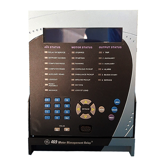
CHAPTER 4: INTERFACES 4.1.3 LED Indicators There are three groups of LED indicators. They are 469 Status, Motor Status, and Output Relays. 806977A1.CDR FIGURE 4–1: 469 LED INDICATORS 469 Status LED Indicators • 469 IN SERVICE: This LED indicates that control power is applied, all monitored inputs/outputs and internal systems are OK, the 469 has been programmed, and the 469 is in protection mode, not simulation mode. -
Page 93: Rs232 Port
EnerVista 469 Setup software. Local interrogation of settings and actual values is also possible. New firmware may also be downloaded to the 469 flash memory through this port. Upgrading of the relay firmware does not require a hardware EPROM change. -
Page 94: Keypad
CHAPTER 4: INTERFACES 4.1.5 Keypad Description The 469 display messages are organized into main menus, pages, and sub-pages. There are three main menus labeled settings, Actual Values, and Target Messages. Pressing the key followed by the key scrolls through the three main... - Page 95 ENTER view the result. Once a character is entered, by pressing the key, it is ENTER automatically saved in Flash Memory, as a new setting. SWITCH NAME: Stn. Monitor 469 MOTOR MANAGEMENT RELAY – INSTRUCTION MANUAL 4–5...
-
Page 96: S Ettings E Ntry
CHAPTER 4: INTERFACES The 469 does not have ‘+’ or ‘–’ keys. Negative numbers may be entered in one of two manners. Immediately pressing one of the keys causes the settings to VALUE scroll through its range including any negative numbers. -
Page 97: D Iagnostic M Essages
These messages provide a summary of the present state of the relay. The Message LED flashes when there are diagnostic messages available; press the key until the relay displays , then press the MENU TARGET MESSAGES 469 MOTOR MANAGEMENT RELAY – INSTRUCTION MANUAL 4–7... - Page 98 4.1.8 Self-Test Warnings The 469 relay performs self test diagnostics at initialization (after power up) and continuously as a background task to ensure the hardware and software is functioning correctly. Self-test warnings indicate either a minor or major problem. Minor problems are problems that does not compromise motor protection.
-
Page 99: F Lash M Essages
Table 4–1: Self-Test Warnings Message Severity Failure description Relay Not Configured This warning occurs when the 469 CT Primary or Minor Consult User Manual FLA is set to “None”. Caused by a failure of the real time clock circuit. Service Required... -
Page 100: Enervista 469 Setup Software Interface
It can be used while disconnected (i.e. off-line) or connected (i.e. on-line) to a 469 device. In off-line mode, Settings files can be created for eventual downloading to the device. -
Page 101: H Ardware
CHAPTER 4: INTERFACES 4.2.2 Hardware Communications from the EnerVista 469 Setup to the 469 can be accomplished three ways: RS232, RS485, and Ethernet communications. The following figures illustrate typical connections for RS232 and RS485 communications. For Ethernet connection details FIGURE 4–2: Communications using The Front RS232 Port 469 MOTOR MANAGEMENT RELAY –... - Page 102 CHAPTER 4: INTERFACES FIGURE 4–3: Communications using Rear RS485 Port 808839A1.CDR FIGURE 4–4: Communications using Rear Ethernet Port 4–12 469 MOTOR MANAGEMENT RELAY – INSTRUCTION MANUAL...
- Page 103 CHAPTER 4: INTERFACES 4.2.3 Installing the EnerVista 469 Setup Software The following minimum requirements must be met for the EnerVista 469 Setup software to operate on your computer. • Pentium class or higher processor (Pentium II 400 MHz or better recommended) •...
- Page 104 CHAPTER 4: INTERFACES Click the Add Now button to list software items for the 469. EnerVista Launchpad will obtain the latest installation software from the Web or CD and automatically start the installation process. A status window with a progress bar will be shown during the downloading process.
- Page 105 EnerVista 469 Setup software to the Windows start menu. Click Finish to end the installation. The 469 device will be added to the list of installed IEDs in the EnerVista Launchpad window, as shown below. 469 MOTOR MANAGEMENT RELAY – INSTRUCTION MANUAL...
- Page 106 “Pumping Station 1” as the site name. Click the OK button when complete. The new site will appear in the upper-left list in the EnerVista 469 Setup window. Click the Add Device button to define the new device. Enter the desired name in the Device Name field and a description (optional) of the site.
- Page 107 Using the Quick Connect Feature The Quick Connect button can be used to establish a fast connection through the front panel RS232 port of a 469 relay. The following window will appear when the Quick Connect button is pressed: 469 MOTOR MANAGEMENT RELAY – INSTRUCTION MANUAL...
- Page 108 As indicated by the window, the Quick Connect feature quickly connects the EnerVista 469 Setup software to a 469 front port with the following settings: 9600 baud, no parity, 8 bits, 1 stop bit. Select the PC communications port connected to the relay and press the Connect button.
- Page 109 The new device will be added to the Site List window (or Online window) located in the top left corner of the main EnerVista 469 Setup window. The 469 Site Device has now been configured for Ethernet communications. Proceed to the following section to begin communications. 4.3.4...
- Page 110 FIGURE 4–5: Main Window after Connection The Front Panel Settings window will open with a corresponding status indicator on the lower left of the EnerVista 469 Setup window. If the status indicator is red, verify that the serial cable is properly connected to the relay, and that the relay has been properly configured for communications (steps described earlier).
- Page 111 Other settings and commands windows can be displayed and edited in a similar manner. Actual values windows are also available for display. These windows can be locked, arranged, and resized at will. Refer to the EnerVista 469 Setup Help File for additional information about the using the Note software.
-
Page 112: Working With Settings And Settings Files
4.4.1 Engaging a Device The EnerVista 469 Setup software may be used in on-line mode (relay connected) to directly communicate with a 469 relay. Communicating relays are organized and grouped by communication interfaces and into sites. Sites may contain any number of relays selected from the SR or UR product series. - Page 113 Opening any EnerVista 469 Setup file will automatically launch the application or provide focus to the already opened application. If the file is a Settings file (has a ‘469’ extension) which had been removed from the Settings List tree menu, it will be added back to the Settings List tree.
- Page 114 • User Memory Map Setting Tool Factory default values are supplied and can be restored after any changes. The EnerVista 469 Setup display relay settings with the same hierarchy as the front panel display. For specific details on settings, refer to Chapter 5.
- Page 115 Open. The new file and complete path will be added to the file list. Creating a New Settings File using Motor Settings Auto-Config The EnerVista 469 Setup software allows the user to create new Settings files independent of a connected device. These can be uploaded to a relay at a later date.
- Page 116 On the main menu, select File > Motor Settings Auto-Config The EnerVista 469 Setup software displays the following box, allowing the configuration of the Settings File as shown. . It is important to define the correct firmware version to ensure that settings not available...
- Page 117 Select the file name and path to store the file, or select any displayed file name to update an existing file. All 469 Settings Files should have the extension ‘469’ (for example, ‘motor1.469’). Click Next and OK to continue the process.
- Page 118 CHAPTER 4: INTERFACES Continue filling in the fields as indicated. Once you have completed all 6 Steps, the final window will show as follows: 4–28 469 MOTOR MANAGEMENT RELAY – INSTRUCTION MANUAL...
- Page 119 Creating a New Settings File without using Motor Settings Auto-Config The EnerVista 469 Setup software allows the user to create new Settings files independent of a connected device. These can be uploaded to a relay at a later date. The following manual procedure - as distinct from the Motor Settings Auto-Config option described above - illustrates how to create new Settings Files.
- Page 120 Select the file name and path to store the file, or select any displayed file name to update an existing file. All 469 Settings Files should have the extension ‘469’ (for example, ‘motor1.469’). Click the appropriate radio button (yes or no) to choose between Auto- Config or manual creation of the Settings File.
- Page 121 Upgrading Settings Files to a New Revision It is often necessary to upgrade the revision code for a previously saved Settings file after the 469 firmware has been upgraded (for example, this is required for firmware upgrades). This is illustrated in the following procedure.
- Page 122 469. Printing Settings and Actual Values The EnerVista 469 Setup software allows the user to print partial or complete lists of settings and actual values. Use the following procedure to print a list of settings: Select a previously saved Settings file in the File pane or establish communications with a 469 device.
- Page 123 4–31 for instructions on changing the revision number of a Settings file. The following procedure illustrates how to load settings from a file. Before loading a Settings file, it must first be added to the EnerVista 469 Setup environment as described in Adding Settings Files to the Environment on page 4–24.
- Page 124 Right-click on the selected file. Select the Write Settings to Device item. The EnerVista 469 Setup software will generate the following warning message, to remind the user to remove the relay from service, before attempting to load settings into an in- service relay.:...
-
Page 125: Upgrading Relay Firmware
4.5.2 Saving Settings to a File Before upgrading firmware, it is very important to save the current 469 settings to a file on your PC. After the firmware has been upgraded, it will be necessary to load this file back into the 469. - Page 126 The EnerVista 469 Setup software now prepares the 469 to receive the new firmware file. The 469 will display a message indicating that it is in Upload Mode. While the file is being loaded into the 469, a status box appears showing how much of the new firmware file has been transferred and how much is remaining, as well as the upgrade status.
- Page 127 Cycling power to the relay is recommended after a firmware upgrade. Note After successfully updating the 469 firmware, the relay will not be in service and will require settings programming. To communicate with the relay, the following settings will have to me manually programmed.
-
Page 128: Advanced Enervista 469 Setup Features
The EnerVista 469 Setup software can be used to capture waveforms (or view trace memory) from the 469 relay at the instance of a trip. A maximum of 128 cycles can be captured and the trigger point can be adjusted to anywhere within the set cycles. A maximum of 16 traces can be buffered (stored) with the buffer/cycle trade-off. - Page 129 CHAPTER 4: INTERFACES The waveform file numbering starts with the number zero in the 469; therefore, the maximum trigger number will always be one less then the total number triggers available. Click on the Save to File button to save the selected waveform to the local PC.
-
Page 130: P Hasors
4.6.3 Phasors The EnerVista 469 Setup software can be used to view the phasor diagram of three-phase currents and voltages. The phasors are for: phase voltages Va, Vb, and Vc; phase currents Ia, Ib, and Ic. With the EnerVista 469 Setup software running and communications established, Open the Actual Values >... - Page 131 The 469 Motor Management Relay was designed to display lagging angles. Therefore, if a system condition would cause the current to lead the voltage by 45°, the 469 relay will display such angle as 315° Lag instead of 45° Lead.
- Page 132 Several parameters can be trended and graphed at sampling periods ranging from 1 second up to 1 hour. The parameters which can be trended by the EnerVista 469 Setup software are: • Currents/Voltages:...
- Page 133 CHAPTER 4: INTERFACES With EnerVista 469 Setup running and communications established, Select the Actual Values > Trending menu item to open the trending window. The following window will appear. To prepare for new trending, Select Stop to stop the data logger and Reset to clear the screen.
- Page 134 Press “Run” to start the data logger. If the Log Samples to File item is selected, the EnerVista 469 Setup software will begin collecting data at the selected sampling rate and will display it on the screen.
-
Page 135: E Vent R Ecorder
4.6.5 Event Recorder The 469 event recorder can be viewed through the EnerVista 469 Setup software. The event recorder stores generator and system information each time an event occurs (e.g. breaker failure). A maximum of 256 events can be stored, where E256 is the most recent event and E01 is the oldest event. -
Page 136: Modbu User Map
CHAPTER 4: INTERFACES 4.6.6 Modbus User Map The EnerVista 469 Setup software provides a means to program the 469 User Map (Modbus addresses 0180h to 01F7h). Refer to GE Publication GEK-106491C: 469 Communications Guide for additional information on the User Map. - Page 137 This includes the maximum temperature measured by each of the 12 RTDs. Event recorder downloading tool Product information This includes model number, firmware version, additional product information, and calibration dates. Oscillography and data logger downloading tool 469 MOTOR MANAGEMENT RELAY – INSTRUCTION MANUAL 4–47...
- Page 138 The windows can be re-arranged to maximize data viewing as shown in the following figure (showing actual current, voltage, and motor status values tiled in the same window): FIGURE 4–10: Actual Values Display 4–48 469 MOTOR MANAGEMENT RELAY – INSTRUCTION MANUAL...
- Page 139 If desired, a short description of site can also be entered along with the display order of devices defined for the site. Click the OK button when complete. The new site will appear in the upper-left list in the EnerVista 469 Setup window. Click the Add Device button to define the new device.
- Page 140 469 Setup to the Relay on page 4–16 for details. FIGURE 4–12: Device Setup Screen (Example) Click the Read Order Code button to connect to the 469 device and upload the order code. If a communications error occurs, ensure that communications values entered in the previous step correspond to the relay setting values.
- Page 141 CHAPTER 4: INTERFACES FIGURE 4–13: ‘Plug and Play’ Dashboard Click the Dashboard button below the 469 icon to view the device information. We have now successfully accessed our 469 through EnerVista Viewpoint. 469 MOTOR MANAGEMENT RELAY – INSTRUCTION MANUAL 4–51...
- Page 142 CHAPTER 4: INTERFACES FIGURE 4–14: EnerVista Plug and Play Screens For additional information on EnerVista viewpoint, please visit the EnerVista website at http://www.enervista.com. 4–52 469 MOTOR MANAGEMENT RELAY – INSTRUCTION MANUAL...
-
Page 143: Overview
Overview 5.1.1 Settings Message Map The 469 has a considerable number of programmable settings which makes it extremely flexible. The settings have been grouped into a number of pages and sub-pages as shown below. Each page of settings (e.g. ) has a section which describes in detail S2 SYSTEM SETUP all the settings found on that page. - Page 144 END OF PAGE MESSAGE See page –34. SETTINGS RELAY MESSAGE See page –35. FORCE END OF PAGE MESSAGE See page –38. SETTINGS THERMAL MESSAGE See page –39. OVERLOAD END OF PAGE MESSAGE 5–2 469 MOTOR MANAGEMENT RELAY – INSTRUCTION MANUAL...
- Page 145 See page –67. JOGGING MESSAGE See page –69. RESTART END OF PAGE MESSAGE See page –70. SETTINGS TYPES MESSAGE See page –71. MESSAGE See page –71. MESSAGE See page –71. ↓ MESSAGE 469 MOTOR MANAGEMENT RELAY – INSTRUCTION MANUAL 5–3...
- Page 146 See page –84. TORQUE MESSAGE See page –85. OVERTORQUE END OF PAGE MESSAGE See page –86. SETTINGS TRIP MESSAGE See page –86. STARTER MESSAGE See page –87. CURRENT MESSAGE See page –87. DEMAND 5–4 469 MOTOR MANAGEMENT RELAY – INSTRUCTION MANUAL...
- Page 147 INPUT ANALOG MESSAGE See page –96. INPUT END OF PAGE MESSAGE See page –98. SETTINGS SIMULATION PRE- MESSAGE See page –99. FAULT MESSAGE See page –100. FAULT MESSAGE See page –101. TEST 469 MOTOR MANAGEMENT RELAY – INSTRUCTION MANUAL 5–5...
- Page 148 Immediately prior to issuing a trip, the 469 takes a snapshot of motor parameters and stores them as pre- trip values which will allow for troubleshooting after the trip occurs. The cause of last trip message is updated with the current trip and the 469 display defaults to that message.
- Page 149 As soon as an alarm occurs, the alarms messages are updated to reflect the alarm and the 469 display defaults to that message. Since it may not be desirable to log all alarms as events, each alarm feature may be programmed to log as an event or not.
-
Page 150: P Asscode
Passcodes are also ignored when programming settings via the RS485 port. However when programming settings using the front RS232 port and the EnerVista 469 Setup software, a passcode is required (if enabled). settings is seen only if the passcode is not 0 and ENTER PASSCODE FOR ACCESS is “Restricted”. -
Page 151: P References
• DISPLAY UPDATE INTERVAL: Sets the duration for which the metered current and voltage readings are averaged before being displayed. It does not affect relay 469 MOTOR MANAGEMENT RELAY – INSTRUCTION MANUAL 5–9... -
Page 152: C Ommunications
The front port is for local use only and responds regardless of the slave address programmed. This port may be connected to a personal computer running EnerVista 469 Setup. The software can download and upload settings files as well as upgrade the 469 firmware. - Page 153 DCS, PLC, or PC. The auxiliary RS485 port may be used for redundancy or, it may be used to talk to auxiliary GE Multilin devices. The RS485 COM2 port is disabled if the Ethernet or DeviceNet option is ordered.
- Page 154 Enter the dedicated MAC ID and baud rate as per the DeviceNet design (Refer to GEK- 106491C: 469 Communications Guide). The DeviceNet option is implemented by the 469 relay using the AnyBus-S DeviceNet (HMS) module as a communication adapter. The module is ODVA certified and acts as a server between the relay and the DeviceNet network.
-
Page 155: Real Time Clock
If the RS485 serial communication link is used, then all the relays can keep synchronized time. A new clock time is pre-loaded into the 469 memory via the RS485 port by a remote computer to each relay connected on the communications channel. After the computer broadcasts (address 0) a “set clock”... -
Page 156: M Essage S Cratchpad
MESSAGE Range: 40 alphanumeric characters TEXT 2 MESSAGE Range: 40 alphanumeric characters TEXT 3 MESSAGE Range: 40 alphanumeric characters TEXT 4 MESSAGE Range: 40 alphanumeric characters GE MULTILIN MESSAGE 469 MOTOR RELAY 5–14 469 MOTOR MANAGEMENT RELAY – INSTRUCTION MANUAL... -
Page 157: Clear Data
CLEAR PEAK DEMAND DATA: Clears the peak demand values. • CLEAR RTD MAXIMUMS: All maximum RTD temperature measurements are stored and updated each time a new maximum temperature is established. This command clears the maximum values. 469 MOTOR MANAGEMENT RELAY – INSTRUCTION MANUAL 5–15... -
Page 158: I Nstallation
Range: No, Yes RESET STARTER MESSAGE INFORMATION: No These commands clear various informative and historical data when the 469 is first applied on a new installation. • RESET MOTOR INFORMATION: Counters for number of motor starts and emergency restarts can be viewed in actual values. The 469 also learns various motor characteristics through motor operation. -
Page 159: S2 System Setup
50:0.025 ground CT input is used. To use the 50:0.025 input, select “50:0.025” for the settings. No additional ground CT messages will appear. On solidly grounded GROUND CT systems where fault currents may be quite large, the 469 1A or 5A secondary ground CT 469 MOTOR MANAGEMENT RELAY – INSTRUCTION MANUAL 5–17... - Page 160 CTs, simply enter the same value here as well. Example 1: Consider a 469 with a 5 A Phase CT secondary and Ground Fault Detection set to Residual and a motor with the following specifications: Motor Nameplate FLA: 87 A; Low Resistance Grounded; Maximum Fault: 400 A The following settings are required: “100”...
-
Page 161: V Oltage S Ensing
S2 SYSTEM SETUP POWER SYSTEM Range: 50 Hz, 60 Hz, Variable NOMINAL SYSTEM POWER FREQUENCY: 60 Hz Range: ABC, ACB SYSTEM PHASE MESSAGE SEQUENCE: ABC Range: ABC, ACB SPEED2 PHASE MESSAGE SEQUENCE: ABC 469 MOTOR MANAGEMENT RELAY – INSTRUCTION MANUAL 5–19... - Page 162 Auxiliary3 TROL If enabled, motor starting and stopping is possible via any of the three 469 communication ports. Refer to GE publication GEK-106491: 469 Communications Guide for command formats. When a stop command is issued, the 1 TRIP relay is activated for 1 second to complete the trip coil circuit for a breaker application or break the contact coil circuit for a contactor application.
- Page 163 MESSAGE START TIMER: 200 The 469 can control the transition of a reduced voltage starter from reduced to full voltage. That transition may be based on “Current Only”, “Current and Timer”, or “Current or Timer” (whichever comes first). When the 469 measures the transition of no motor current to some value of motor current, a 'Start' is assumed to be occurring (typically current will rise quickly to a value in excess of FLA, e.g.
- Page 164 Auxiliary ‘b’ contacts from the reduced voltage contactor and the full voltage contactor. Once transition is initiated, the 469 assumes the motor is still running for at least 2 seconds. This prevents the 469 from recognizing an additional start if motor current goes to zero during an open transition.
- Page 165 REDUCED VOLTAGE STARTER AUXILIARY ‘A’ STATUS INPUT REDUCED VOLTAGE AUXILIARY ‘b’ STARTER STATUS SWITCH INPUT (Setpoint = ‘Starter Auxiliary B’) FULL VOLTAGE AUXILIARY ‘b’ REDUCED VOLTAGE STARTER AUXILIARY ‘B’ STATUS INPUT 808723A1.CDR FIGURE 5–3: Reduced Voltage Starter Inputs 469 MOTOR MANAGEMENT RELAY – INSTRUCTION MANUAL 5–23...
-
Page 166: S3 Digital Inputs
(see Passcode on page 5–8). Test Switch Once the 469 is in service, it may be tested from time to time as part of a regular maintenance schedule. The relay will have accumulated statistical information relating historically to starter and motor operation. This information includes: last trip data,... -
Page 167: S Tarter S Tatus
Starter Auxiliary B STARTER This input is necessary for all motors. The 469 determines that a motor has stopped when the phase current falls below the level that the relay can measure (5% of CT primary). Monitoring an auxiliary contact from the breaker or contactor prevents the relay from detecting additional starts when an unloaded motor is loaded, or issuing a block start after an unloaded motor is started and running at less than 5% CT rated primary current. - Page 168 D23 are monitored for a contact closure. Closure of the contact signifies that the motor is in Speed 2 or High Speed. If the input is open, it signifies that the motor is in Speed 1. This allows the 469 to determine which settings should be active at any given point in time. Remote Alarm...
- Page 169 A trip relay may be selected. A contact closure on the switch input assigned as load shed trip will cause a trip within 100 ms. 469 MOTOR MANAGEMENT RELAY – INSTRUCTION MANUAL 5–27...
- Page 170 Block time indicates that the feature is always active, when the motor is stopped or running. After the block delay has expired, the digital input will be monitored. If a closure occurs, after the specified delay, a trip will occur. 5–28 469 MOTOR MANAGEMENT RELAY – INSTRUCTION MANUAL...
- Page 171 Once Vibration Switch Trip is chosen for a digital input, the settings shown follow the assignment message. When the motor is stopped or running, the digital input will be monitored. If a closure occurs, a trip will occur after the specified delay. 469 MOTOR MANAGEMENT RELAY – INSTRUCTION MANUAL 5–29...
- Page 172 Tachometer PATH: SETTINGS S3 DIGITAL INPUTS ASSIGNABLE INPUT 1(4) Range: See above INPUT 1 FUNCTION: ASSIGNABLE Tachometer Range: 100 to 7200 RPM in steps of 1 RATED SPEED: MESSAGE 3600 RPM 5–30 469 MOTOR MANAGEMENT RELAY – INSTRUCTION MANUAL...
- Page 173 The probe could be powered from the +24 V from the input switch power supply. The NPN transistor output could be taken to one of the assignable switch inputs configured as a tachometer. 469 MOTOR MANAGEMENT RELAY – INSTRUCTION MANUAL 5–31...
- Page 174 If the switch is not in its normal state after the specified delay, an alarm or trip will occur. Capture Trace PATH: SETTINGS S3 DIGITAL INPUTS ASSIGNABLE INPUT 1(4) Range: See above. INPUT 1 FUNCTION: ASSIGNABLE Capture Trace 5–32 469 MOTOR MANAGEMENT RELAY – INSTRUCTION MANUAL...
- Page 175 S13 469 TESTING SIMULATION MODE setting via a switch input. This is typically used for relay or system SIMULATION MODE testing. There are no additional Digital Input settings associated with this value. 469 MOTOR MANAGEMENT RELAY – INSTRUCTION MANUAL 5–33...
-
Page 176: S4 Output Relays
Obviously, when control power is lost to the 469, the output relays must be de-energized and therefore, they will be in their non- operated state. Shorting bars in the drawout case ensure that when the 469 is drawn out, no trip or alarm occurs. -
Page 177: Force Output Relay
NOT allowed when the selected relay output is already FORCE OUTPUT RELAY active due to trip or alarm condition, when the 469 is in start block condition, or when the 469 is not in service. IMPORTANT NOTE: The forced relay will override any trip or alarm conditions. (i.e. when the Note relay is forced and trip occurs, the relay will still be enabled when the trip condition is reset). -
Page 178: S5 Thermal Model
The motor manufacturer should provide a safe stall time or thermal limit curves for any motor they sell. To program the 469 for maximum protection, it is necessary to ask for these items when the motor is out for bid. These thermal limits are intended to be used as guidelines and their definition is not always precise. - Page 179 CURVES AT 100%, 90%, AND 80%VOLTAGE, REPECTIVELY E,F, AND G ARE THE SAFE STALL THERMAL LIMIT TIMES AT 100%, 90%, AND 80%VOLTAGE, REPECTIVELY % CURRENT 806827A1.CDR FIGURE 5–5: Typical Time-Current and Thermal Limit Curves (ANSI/IEEE C37.96) 469 MOTOR MANAGEMENT RELAY – INSTRUCTION MANUAL 5–37...
-
Page 180: Thermal Model
MESSAGE ALARM EVENTS: Off The primary protective function of the 469 is the thermal model. It consists of five key elements: the overload curve and overload pickup level, the unbalance biasing of the motor current while the motor is running, the motor cooling time constants, and the biasing of the thermal model based on Hot/Cold motor information and measured stator temperature. - Page 181 The 469 overload curve can take one of three formats: Standard, Custom Curve, or Voltage Dependent. Regardless of the selected curve style, thermal memory is retained in the register.
- Page 182 If the motor starting times are well within the safe stall times, it is recommended that the 469 Standard Overload Curve be used. The standard overload curves are a series of 15 curves with a common curve shape based on typical motor thermal limit curves (see the figure and table below).
- Page 183 CHAPTER 5: SETTINGS Table 5–1: 469 Standard Overload Curve Multipliers PICKUP STANDARD CURVE MULTIPLIERS (× FLA) × 1 × 2 × 3 × 4 × 5 × 6 × 7 × 8 × 9 × 10 × 11 × 12 ×...
- Page 184 CHAPTER 5: SETTINGS Table 5–1: 469 Standard Overload Curve Multipliers PICKUP STANDARD CURVE MULTIPLIERS (× FLA) × 1 × 2 × 3 × 4 × 5 × 6 × 7 × 8 × 9 × 10 × 11 × 12 ×...
- Page 185 Range: 0.5 to 99999.9 s in steps of 0.1 TIME TO TRIP AT MESSAGE 4.25 x FLA: 20.5 Range: 0.5 to 99999.9 s in steps of 0.1 TIME TO TRIP AT MESSAGE 4.50 x FLA: 18.2 469 MOTOR MANAGEMENT RELAY – INSTRUCTION MANUAL 5–43...
- Page 186 The distinct parts of the thermal limit curves now become more critical. For these conditions, it is recommended that the 469 custom curve thermal model be used. The custom overload curve feature allows the user to program their own curve by entering trip times for 30 pre-determined current levels.
- Page 187 MULTIPLE OF FULL LOAD CURRENT SETPOINT 806803A6.CDR FIGURE 5–7: Custom Curve Example During the interval of discontinuity, the longer of the two trip times is used to reduce the Note chance of nuisance tripping during motor starts. 469 MOTOR MANAGEMENT RELAY – INSTRUCTION MANUAL 5–45...
- Page 188 Range: 0.5 to 99999.9 s in steps of 0.1 TIME TO TRIP AT MESSAGE 4.25 x FLA: 20.5 Range: 0.5 to 99999.9 s in steps of 0.1 TIME TO TRIP AT MESSAGE 4.50 x FLA: 18.2 5–46 469 MOTOR MANAGEMENT RELAY – INSTRUCTION MANUAL...
- Page 189 The relay protecting the motor must be able to distinguish between a locked rotor condition, an accelerating condition, and a running condition. The Voltage Dependent 469 MOTOR MANAGEMENT RELAY – INSTRUCTION MANUAL 5–47...
- Page 190 The change in impedance is reflected by motor terminal voltage and line current. For any given speed at any given line voltage, there is only one value of line current. 5–48 469 MOTOR MANAGEMENT RELAY – INSTRUCTION MANUAL...
- Page 191 Enter the per unit current value for the acceleration overload curve intersect with the custom curve for 100% line voltage. Also enter the per unit current and safe stall protection time for 100% line voltage (see the Acceleration Curves below). 469 MOTOR MANAGEMENT RELAY – INSTRUCTION MANUAL 5–49...
- Page 192 GE Multilin HIGH INERTIA LOAD OVERLOAD CURVES 8800 HP, 13.2 kV, REACTOR COOLANT PUMP 1000 469 Custom Curve MULTIPLES OF FULL LOAD AMPS 806822A4.CDR FIGURE 5–9: Voltage Dependent Overload Curve (Custom Curve) 5–50 469 MOTOR MANAGEMENT RELAY – INSTRUCTION MANUAL...
- Page 193 HIGH INERTIA LOAD OVERLOAD CURVES 8800 HP, 13.2 kV, REACTOR COOLANT PUMP 1000 Acceleration intersect at 80%V Acceleration Intersect at 100%V MULTIPLES OF FULL LOAD AMPS 806823A4.CDR FIGURE 5–10: Voltage Dependent Overload Curves (Acceleration Curves) 469 MOTOR MANAGEMENT RELAY – INSTRUCTION MANUAL 5–51...
- Page 194 The 469 takes the information provided and create protection curves for any voltage between the minimum and 100%. For values above the voltage in question, the 469 extrapolates the safe stall protection curve to 110% voltage. This current level is calculated by taking the locked rotor current at 100% voltage and multiplying by 1.10.
- Page 195 The following two figures illustrate the resultant overload protection curves for 80% and 100% line voltage, respectively. For voltages in between, the 469 will shift the acceleration curve linearly and constantly based on measured line voltage during a motor start.
- Page 196 120 Hz for a 60 Hz system. The skin effect in the rotor bars at this frequency causes a significant increase in rotor resistance and therefore a significant increase in rotor heating. 5–54 469 MOTOR MANAGEMENT RELAY – INSTRUCTION MANUAL...
- Page 197 The 469 measures the ratio of negative to positive-sequence current. The thermal model may be biased to reflect the additional heating that is caused by negative sequence current when the motor is running.
- Page 198 FIGURE 5–15: Thermal Model Cooling Hot/Cold Safe Stall Ratio The motor manufacturer may provide thermal limit information for a hot/cold motor. The 469 thermal model adapts for these conditions if the settings HOT/COLD SAFE STALL RATIO is programmed. This settings value dictates the level of thermal capacity used the relay will settle at for current levels below the .
- Page 199 HOT/COLD SAFE STALL RATIO RTD Bias The 469 thermal replica operates as a complete and independent model. However, the thermal overload curves are based solely on measured current, assuming normal 40°C ambient and normal motor cooling. If the ambient temperature is unusually high, or motor cooling is blocked, the motor temperature will increase.
- Page 200 Presumably, the motor would trip on stator RTD temperature at that time. RTD Bias Maximum Hot/Cold = 0.85 Rated Temperature=130°C Insulation Rating=155°C RTD Bias Center Point RTD Bias Minimum –50 Maximum Stator RTD Temperature FIGURE 5–16: RTD Bias Curve 5–58 469 MOTOR MANAGEMENT RELAY – INSTRUCTION MANUAL...
- Page 201 TRIP DELAY application so it still responds very fast but rides through normal operational disturbances. Normally, the is set as quick as possible, 0 ms. This time may INTENTIONAL S/C TRIP DELAY 469 MOTOR MANAGEMENT RELAY – INSTRUCTION MANUAL 5–59...
-
Page 202: O Verload A Larm
RELAYS: Range: 1.01 to 3.00 x FLA in steps of MECHANICAL JAM MESSAGE 0.01 PICKUP: 1.50 x Range: 1 to 30 s in steps of 1 MECHANICAL JAM MESSAGE DELAY: 1 s 5–60 469 MOTOR MANAGEMENT RELAY – INSTRUCTION MANUAL... -
Page 203: U Ndercurrent
The level should be set lower than UNDERCURRENT ALARM PICKUP motor loading during normal operations. 469 MOTOR MANAGEMENT RELAY – INSTRUCTION MANUAL 5–61... -
Page 204: C Urrent U Nbalance
CURRENT UNBALANCE MESSAGE TRIP DELAY: 1 s For the 469 relay, unbalance is defined as the ratio of negative-sequence to positive- sequence current, I , if the motor is operating at a load (I ) greater than FLA. If the... -
Page 205: Ground Fault
Range: 0 to 1000 ms in steps of 1 INTENTIONAL GF MESSAGE TRIP Range: On, Off GROUND FAULT TRIP MESSAGE BACKUP: Off Range: Auxiliary2, Aux2 & Aux3, ASSIGN BACKUP MESSAGE Auxiliary3 RELAYS: 469 MOTOR MANAGEMENT RELAY – INSTRUCTION MANUAL 5–63... -
Page 206: P Hase D Ifferential
CTs to react differently and the net current into the ground input of the 469 will not be negligible. A 20 ms block of the ground fault elements when the motor starts enables the 469 to ride through this momentary ground current signal. - Page 207 STARTING DIFF. TRIP DELAY ride through the problem period during start. The running differential delay can then be fine tuned to an application such that it responds very fast to sensitive (low) differential current levels. 469 MOTOR MANAGEMENT RELAY – INSTRUCTION MANUAL 5–65...
-
Page 208: S7 Motor Starting
If enabled, the Acceleration Timer functions as follows. A motor start is assumed to be occurring when the 469 measures the transition of no motor current to some value of motor current. Typically current rises quickly to a value in excess of FLA (e.g. 6 x FLA). At this... -
Page 209: Jogging Block
It may also cause a lockout time that exceeds a Time Between Starts lockout that may have been active. Such a thermal lockout will remain until the motor has cooled to an acceptable temperature for a start. 469 MOTOR MANAGEMENT RELAY – INSTRUCTION MANUAL 5–67... - Page 210 Time Between Starts Permissible: A motor start is assumed to be occurring when the 469 measures the transition of no motor current to some value of motor current. At this point, the Time Between Starts timer is loaded with the entered time. Even unsuccessful start attempts will be logged as starts for this feature.
-
Page 211: Restart Block
The motor has now become a generator and applying supply voltage out of phase may result in catastrophic failure. The Restart Block feature is strictly a timer. The 469 does not sense rotor rotation. Note 469 MOTOR MANAGEMENT RELAY – INSTRUCTION MANUAL... -
Page 212: S8 Rtd Temperature
134.70 191.64 159.70 12.51 138.50 200.64 167.20 12.90 142.29 209.85 174.87 13.28 146.06 219.29 182.75 13.67 149.82 228.96 190.80 14.06 153.58 238.85 199.04 14.44 157.32 248.95 207.45 14.83 161.04 259.30 216.08 15.22 5–70 469 MOTOR MANAGEMENT RELAY – INSTRUCTION MANUAL... - Page 213 RTD #1 TRIP: MESSAGE Range: RTD #1 to RTD #12 RTD #1 TRIP VOT- MESSAGE ING: Range: Trip, Trip & Auxiliary2, Trip & ASSIGN TRIP MESSAGE Aux2 & Aux3, Trip & Auxiliary3 RELAYS: 469 MOTOR MANAGEMENT RELAY – INSTRUCTION MANUAL 5–71...
- Page 214 ING: Range: Trip, Trip & Auxiliary2, Trip & ASSIGN TRIP MESSAGE Aux2 & Aux3, Trip & Auxiliary3 RELAYS: Range: 1 to 250°C in steps of 1 RTD #7 TRIP MESSAGE TEMPERATURE: 90°C 5–72 469 MOTOR MANAGEMENT RELAY – INSTRUCTION MANUAL...
- Page 215 RTD 11 defaults to “Other” RTD type. The Other selection allows the RTD to be used to monitor any temperature that might be required, either for a process or additional bearings or other. There are individual alarm, high alarm and trip configurations for this 469 MOTOR MANAGEMENT RELAY – INSTRUCTION MANUAL 5–73...
- Page 216 RTD malfunction. If enabled, a second RTD must also exceed the trip temperature of the RTD being checked before a trip will be issued. If the RTD is chosen to vote with itself, the voting feature is disabled. The RTD name may be changed if desired. 5–74 469 MOTOR MANAGEMENT RELAY – INSTRUCTION MANUAL...
- Page 217 MESSAGE ALARM EVENTS: Off The 469 has an Open RTD Sensor alarm. This alarm will look at all RTDs that have either an alarm or trip programmed and determine if an RTD connection has been broken. Any RTDs that do not have a trip or alarm associated with them will be ignored for this feature. When a broken sensor is detected, the assigned output relay will operate and a message will appear on the display identifying the RTD that is broken.
-
Page 218: S9 Voltage Elements
Programming “No” for this settings ensures that the motor is tripped and may be restarted only after the bus is re-energized. 5–76 469 MOTOR MANAGEMENT RELAY – INSTRUCTION MANUAL... - Page 219 If the alarm is caused by an abnormal system conditions, a significant amount of unbalance current will be present. If the condition is not detected on time, the unbalance function or the underpower element will trip the motor. 469 MOTOR MANAGEMENT RELAY – INSTRUCTION MANUAL 5–77...
-
Page 220: O Vervoltage
PATH: SETTINGS S9 VOLTAGE ELEM. PHASE REVERSAL Range: Off, Latched, Unlatched PHASE REVERSAL PHASE TRIP: Off Range: Trip, Trip & Auxiliary2, Trip & ASSIGN TRIP MESSAGE Aux2 & Aux3, Trip & Auxiliary3 RELAYS: 5–78 469 MOTOR MANAGEMENT RELAY – INSTRUCTION MANUAL... -
Page 221: F Requency
CHAPTER 5: SETTINGS The 469 can detect the phase rotation of the three phase voltage. If the Phase Reversal feature is turned on when all 3 phase voltages are greater than 50% motor nameplate voltage, and the phase rotation of the three phase voltages is not the same as the settings, a trip and block start will occur in 500 to 700 ms. -
Page 222: S10 Power Elements
By convention, an induction motor consumes Watts and vars. This condition is displayed on the 469 as +Watts and +vars. A synchronous motor can consume Watts and vars or consume Watts and generate vars. These conditions are displayed on the 469 as +Watts, +vars, and +Watts, –vars respectively (see the figure below). -
Page 223: Power Factor
MESSAGE DELAY: 1.0 s If the 469 is applied on a synchronous motor, it is desirable not to trip or alarm on power factor until the field has been applied. Therefore, this feature can be blocked until the motor comes up to speed and the field is applied. From that point forward, the power factor trip and alarm elements will be active. -
Page 224: R Eactive P Ower
MESSAGE TRIP If the 469 is applied on a synchronous motor, it is desirable not to trip or alarm on kvar until the field has been applied. Therefore, this feature can be blocked until the motor comes up to speed and the field is applied. From that point forward, the kvar trip and alarm elements will be active. -
Page 225: U Nderpower
Power is a more accurate representation of loading and may be used for more sensitive detection of load loss or pump cavitation. This may be especially useful for detecting process related problems. 469 MOTOR MANAGEMENT RELAY – INSTRUCTION MANUAL 5–83... -
Page 226: Reverse Power
Disabled Range: 0.001 to 50.000 mΩ in steps of STATOR RESIS- MESSAGE 0.001 TANCE: Range: 2 to 128 in steps of 1 POLE PAIRS: MESSAGE Range: Newton-meter, Foot-pound TORQUE UNIT: MESSAGE Newton-meter 5–84 469 MOTOR MANAGEMENT RELAY – INSTRUCTION MANUAL... -
Page 227: O Vertorque
Detection of a motor overtorque condition, usually done to protect devices driven by the motor, can be set up here. The assigned relay activates when the torque measured exceeds the specified level for the specified time duration. 469 MOTOR MANAGEMENT RELAY – INSTRUCTION MANUAL 5–85... -
Page 228: S11 Monitoring
“Latched” or “Unlatched”, then the Starter Status STARTER FAILURE ALARM input and motor current are monitored when the 469 initiates a trip. If the starter status contacts do not change state or motor current does not drop to zero after the programmed time delay, an alarm occurs. -
Page 229: Demand
ASSIGN ALARM MESSAGE Alarm & Aux2 & Aux3, Alarm & RELAYS: Auxiliary3, Auxiliary2, Aux2 & Aux3, Auxiliary3 Range: 10 to 100000 A in steps of 1 CURRENT DEMAND MESSAGE LIMIT: 100 A 469 MOTOR MANAGEMENT RELAY – INSTRUCTION MANUAL 5–87... - Page 230 MESSAGE ALARM EVENTS: Off The 469 measures motor demand for several parameters (current, kW, kvar, and kVA). These values may be of interest for energy management programs where processes may be altered or scheduled to reduce overall demand on a feeder.
-
Page 231: Pulse Output
Range: 1 to 50000 kvarh in steps of 1 NEG kvarh PULSE MESSAGE Range: Off, Alarm, Auxiliary2, RUNNING TIME MESSAGE Auxiliary3 PULSE Range: 1 to 50000 s in steps of 1 RUNNING TIME MESSAGE PULSE 469 MOTOR MANAGEMENT RELAY – INSTRUCTION MANUAL 5–89... - Page 232 1 second. This feature should be programmed such that no more than one pulse per second will be Note required or the pulsing will lag behind the interval activation. 5–90 469 MOTOR MANAGEMENT RELAY – INSTRUCTION MANUAL...
-
Page 233: S12 Analog Inputs/Outputs
MESSAGE MAX: 1000 kW The 469 has four analog output channels (4 to 20 mA or 0 to 1 mA as ordered). Each channel may be individually configured to represent a number of different measured parameters as shown in the table below. The minimum value programmed represents the 4 mA output. - Page 234 1250 kVA Demand 0 to 50000 kVA 1500 Motor Load 0.00 to 20.00 x FLA 0.01 0.00 1.25 Analog Inputs 1-4 –50000 to +50000 +50000 Tachometer 100 to 7200 RPM 3500 3700 5–92 469 MOTOR MANAGEMENT RELAY – INSTRUCTION MANUAL...
-
Page 235: Analog Input 1 To
ANALOG INPUT 1 MESSAGE ALARM Range: Off, Latched, Unlatched ANALOG INPUT 1 MESSAGE TRIP: Off Range: Trip, Trip & Auxiliary2, Trip & ASSIGN TRIP MESSAGE Aux2 & Aux3 Trip & Auxiliary3 RELAYS: 469 MOTOR MANAGEMENT RELAY – INSTRUCTION MANUAL 5–93... - Page 236 “0” minutes. Set the alarm for a BLOCK ANALOG INPUT 1(4) FROM START reasonable level slightly higher than the normal vibration level. Program a delay of “3 s” and a pickup value of “Over”. 5–94 469 MOTOR MANAGEMENT RELAY – INSTRUCTION MANUAL...
- Page 237 The comparison logic can also be selected as one input greater than the other (“1>2”) or vice versa (“2>1”) or as absolute difference (“1<>2”). The compared analog inputs must be programmed with the same units type prior to programming this feature. 469 MOTOR MANAGEMENT RELAY – INSTRUCTION MANUAL 5–95...
- Page 238 CHAPTER 5: SETTINGS For example, two motors on a dual motor drive are each protected a 469. The motors should be at the same power level (kW). Connect the analog outputs (programmed for kW) from both relays to the analog inputs of one relay. Program the analog input differential to monitor the two motors kW and trip at a predetermined level.
- Page 239 (“3>4”) or vice versa (“4>3”) or as absolute difference (“3<>4”). Note that the compared analog inputs must be programmed with the same unit type prior to using this feature. 469 MOTOR MANAGEMENT RELAY – INSTRUCTION MANUAL 5–97...
-
Page 240: S13 469 Testing
If however, the 469 has been installed and will remain installed on a specific motor, it might be desirable to short the 469 Test input (C3 and C4) to prevent all of this data from being corrupted or updated. In any case, when in simulation mode, the 469 In Service LED (indicator) will flash, indicating that the 469 is not in protection mode. - Page 241 Range: 0 to 100% in steps of 1 PRE-FAULT ANALOG MESSAGE INPUT 4: 0% The values entered under Pre-Fault Values will be substituted for the measured values in the 469 when the simulation mode is “Simulate Pre-Fault”. 469 MOTOR MANAGEMENT RELAY – INSTRUCTION MANUAL 5–99...
- Page 242 Range: 0 to 100% in steps of 1 FAULT ANALOG MESSAGE INPUT 4: 0% The values entered under Fault Values will be substituted for the measured values in the 469 when the simulation mode is “Simulate Fault”. 5–100 469 MOTOR MANAGEMENT RELAY – INSTRUCTION MANUAL...
-
Page 243: Test Output Relay
FORCE OPERATION OF RELAYS output relays will revert back to their normal states. If any relay is forced, the 469 In Service LED will flash, indicating that the 469 is not in protection mode. 5.14.5 Test Analog Outputs... -
Page 244: Comm Port Monitor
During the course of troubleshooting communications problems, it can be very useful to see the data that is first being transmitted to the 469 from some master device, and then see the data that the 469 transmits back to that master device. The messages shown here should make it possible to view that data. -
Page 245: S14 Two-Speed Motor
Speed 2; if the input is open, it signifies that the motor is in Speed 1. This allows the 469 to determine which settings should be active at any given point in time. Two-speed motor protection is enabled with the... - Page 246 Range: 0.5 to 99999.9 in steps of 0.1 SPEED2 TRIP AT MESSAGE 6.50 x FLA: 8.5 s Range: 0.5 to 99999.9 in steps of 0.1 SPEED2 TRIP AT MESSAGE 7.00 x FLA: 7.3 s 5–104 469 MOTOR MANAGEMENT RELAY – INSTRUCTION MANUAL...
- Page 247 Range: 0.5 to 99999.9 in steps of 0.1 SPEED2 TRIP AT MESSAGE 2.50 x FLA: 66.6 Range: 0.5 to 99999.9 in steps of 0.1 SPEED2 TRIP AT MESSAGE 2.75 x FLA: 53.3 469 MOTOR MANAGEMENT RELAY – INSTRUCTION MANUAL 5–105...
- Page 248 SPEED2 MIN ALLOW- MESSAGE ABLE Range: 2.00 to 15.00 x FLA in steps of SPEED2 ISTALL @ MESSAGE 0.01 Range: 0.5 to 999.9 s in steps of 0.1 SPEED2 SAFE STALL MESSAGE 5–106 469 MOTOR MANAGEMENT RELAY – INSTRUCTION MANUAL...
- Page 249 S14 2-SPEED MOTOR SPEED2 ACCELERATION Range: 1.0 to 250.0 s in steps of 0.1 SPEED2 ACCEL. SPEED2 TIMER Range: 1.0 to 250.0 s in steps of 0.1 ACCEL. TIMER FROM MESSAGE SPEED1-2: 10.0 s 469 MOTOR MANAGEMENT RELAY – INSTRUCTION MANUAL 5–107...
- Page 250 Speed 2 from a stopped condition. The other is an acceleration timer for the transition from Speed 1 to Speed 2. Also, while the motor is running, the 469 will ignore Mechanical Jam protection during the acceleration from Speed 1 to Speed 2 until the motor current has dropped below Speed 2 FLA ×...
-
Page 251: Overview
MESSAGE See page –7. STATUS START MESSAGE See page –9. BLOCKS MESSAGE See page –9. DIGITAL REAL MESSAGE See page –10. TIME END OF PAGE MESSAGE ACTUAL See page –11. VALUES CURRENT 469 MOTOR MANAGEMENT RELAY – INSTRUCTION MANUAL 6–1... - Page 252 INPUT END OF PAGE MESSAGE ACTUAL See page –30. VALUES TRIP MESSAGE See page –31. GENERAL MESSAGE See page –32. TIMERS END OF PAGE MESSAGE ACTUAL EVENT See page –33. VALUES ↓ 6–2 469 MOTOR MANAGEMENT RELAY – INSTRUCTION MANUAL...
-
Page 253: D Escription
Value mode. Actual values may be accessed via one of the following methods: The front panel, using the keys and display. The front program port and a portable computer running the EnerVista 469 Setup software supplied with the relay. The rear RS485 port and a PLC/SCADA system running user-written software. -
Page 254: A1 Status
MESSAGE Established, Time-out, CONNECTN: Nonex- Deferred Delete Range: Nonexistent, Configuring, COS CONNECTION MESSAGE Established, Time-out, STATUS: Nonexis- Deferred Delete These values appear when the relay is ordered with the DeviceNet (D) option. 6–4 469 MOTOR MANAGEMENT RELAY – INSTRUCTION MANUAL... -
Page 255: Last Trip Data
Low Speed These messages describe the motor status at any given point in time. If the motor has been tripped and the 469 has not yet been reset, the value will be “Tripped”. MOTOR STATUS... - Page 256 Analog Input 4 is “Disabled”. PreTrip: 0 Units Immediately prior to issuing a trip, the 469 takes a snapshot of motor parameters and stores them as pre-trip values that allow for troubleshooting after the trip occurs. The message is updated with the current trip and the screen defaults to CAUSE OF LAST TRIP that message.
- Page 257 Rated Vab= 4992 V 120% Range: 0.00, 20.00 to 120.00 Hz SYSTEM FREQUENCY MESSAGE ALARM: 59.4 Hz Range: 0.00 to 0.99 Lead or Lag, 0.00, POWER FACTOR MESSAGE 1.00 ALARM PF: 0.00 469 MOTOR MANAGEMENT RELAY – INSTRUCTION MANUAL 6–7...
- Page 258 The status is “Active” if the condition that caused the alarm is still present. If the 469 chassis is only partially engaged with the case, the ALARM, 469 NOT INSERTED service alarm appears after 1 second. Secure the chassis handle to ensure that PROPERLY all contacts mate properly.
-
Page 259: D Igital I Nputs
Range: Open, Shorted EMERGENCY RESTART MESSAGE SWITCH STATE: Range: Open, Shorted REMOTE RESET MESSAGE SWITCH STATE: Range: Open, Shorted ASSIGNABLE DIGI- MESSAGE Range: Open, Shorted ASSIGNABLE DIGI- MESSAGE Range: Open, Shorted ASSIGNABLE DIGI- MESSAGE 469 MOTOR MANAGEMENT RELAY – INSTRUCTION MANUAL 6–9... -
Page 260: Real Time Clock
Range: 01 to 12 / 01 to 31 / 1995 to REAL DATE: 01/01/1994 2094 TIME TIME: 12:00:00 CLOCK The time and date from the 469 real time clock may be viewed here. 6–10 469 MOTOR MANAGEMENT RELAY – INSTRUCTION MANUAL... -
Page 261: A2 Metering Data
/ FLA. This derating is necessary to prevent nuisance alarms and trips when a motor is lightly loaded. The value shows the U/B BIASED MOTOR LOAD equivalent motor heating current caused by the unbalance k factor. 469 MOTOR MANAGEMENT RELAY – INSTRUCTION MANUAL 6–11... -
Page 262: T Emperature
RTD is set as “Stator”. If no RTDs are programmed in , the THIS FEATURE NOT S8 RTD TEMPERATURE flash message will appear when an attempt is made to enter this group of PROGRAMMED messages. 6–12 469 MOTOR MANAGEMENT RELAY – INSTRUCTION MANUAL... -
Page 263: V Oltage M Etering
If no digital input is configured as tachometer in S3 DIGITAL INPUTS ASSIGNABLE , the flash message will appear when an THIS FEATURE NOT PROGRAMMED INPUT1(4) attempt is made to enter this group of messages. 469 MOTOR MANAGEMENT RELAY – INSTRUCTION MANUAL 6–13... -
Page 264: P Ower M Etering
Real Power (hp) is converted directly from Real Power (kW). This display-only value is not Note used for protection functions. This message will not display more than 65535 hp regardless of the actual kW that are being metered. 6–14 469 MOTOR MANAGEMENT RELAY – INSTRUCTION MANUAL... -
Page 265: D Emand M Etering
Range: –5100 to 4900%. Seen only if ANALOG 1-2 MESSAGE Analog In Diff 1-2 set to %Diff 0 Percent Range: –100000 to 100000. Seen only ANALOG 1-2 MESSAGE if Analog In Diff 1-2 is Abs Diff 0 Units 469 MOTOR MANAGEMENT RELAY – INSTRUCTION MANUAL 6–15... -
Page 266: P Hasors
EnerVista 469 Setup software are not fixed values. The EnerVista 469 Setup software is a useful tool to view the vectors seen by the relay in graphical format. The same information described above is displayed by the EnerVista 469 Setup software as follows: 6–16... - Page 267 Load FIGURE 6–2: Flow Direction of Signed Values for Watts and Vars All phasors calculated by 469 relays are rotating phasors that maintain the correct phase angle relationships with each other at all times. For display purposes, all phasor angles in a given relay are referred to phase Van or Vab, depending on the settings.
- Page 268 30 degrees. FIGURE 6–4: Current Lagging Voltage by 30° Display The phasors shown by the relay and the EnerVista 469 Setup software are a clear representation of the relationship between the system quantities as seen by the relay.
- Page 269 ) and G1 (V ) is displayed by the relay as “Vc Phasor” and “Vcb” by the EnerVista 469 Setup software. In this case, Vc Phasor is equal to the system quantity Vcb or –Vbc. • The voltage between H2 (V ) and G1 (V ) is zero.
- Page 270 : “100.0% at 48° Lag” IA PHASOR : “100.0% at 168° Lag” IB PHASOR : “100.0% at 288° Lag” IC PHASOR The EnerVista 469 Setup software displays the following screen for A2 METERING DATA values: PHASORS 6–20 469 MOTOR MANAGEMENT RELAY – INSTRUCTION MANUAL...
- Page 271 FIGURE 6–7: Phasor Diagram for Open Delta Example Table 6–1: Three-phase Open Delta VT Connection 0.3 pf (72.5°) 0.7 pf 1.00 pf 0.7 pf 0.3 pf (72.5°) Rotation (45°) lag (0°) lag (45°) lead lead 0° 0° 0° 469 MOTOR MANAGEMENT RELAY – INSTRUCTION MANUAL 6–21...
- Page 272 0.3 pf (72.5°) 0.7 pf 1.00 pf 0.7 pf 0.3 pf (72.5°) Rotation (45°) lag (0°) lag (45°) lead lead 0° 0° 0° ---- ---- ---- ---- ---- kVAR – – + (=kW) 6–22 469 MOTOR MANAGEMENT RELAY – INSTRUCTION MANUAL...
- Page 273 FIGURE 6–9: Typical Phasor Diagram for Wye Connection Using the same example as for the open delta connection, except for the VT CONNECTION setting to “Wye”, the following quantities are displayed by the relay and EnerVista 469 TYPE Setup software:...
- Page 274 18.2° is the angle between Van and Ia, Vbn and Ib, and Vcn and Ic. The phase-to-phase quantities are not shown in the menu A2 METERING DATA PHASORS and the EnerVista 469 Setup software. However, they are shown on the following figure. Phase Rotation System Voltages: Van; Vab Vbn; Vbc Vcn;...
- Page 275 – – + (= kW) 0.3 pf (72.5°) 0.7 pf 1.00 pf 0.7 pf 0.3 pf (72.5°) rotation (45°) lag (0°) lag (45°) lead lead 0° lag 0° lag 0° lag 469 MOTOR MANAGEMENT RELAY – INSTRUCTION MANUAL 6–25...
- Page 276 CHAPTER 6: ACTUAL VALUES Table 6–2: Three-phase Wye VT Connection 0.3 pf (72.5°) 0.7 pf 1.00 pf 0.7 pf 0.3 pf (72.5°) rotation (45°) lag (0°) lag (45°) lead lead kVAR – – + (=kW) 6–26 469 MOTOR MANAGEMENT RELAY – INSTRUCTION MANUAL...
-
Page 277: A3 Learned Data
MESSAGE CAPACITY: 0% used The 469 learns the acceleration time, the starting current, as well as, the thermal capacity required during motor starts. This data is accumulated based on the last five starts. The 469 also keeps statistics for last acceleration time, last starting current, and last starting capacity. -
Page 278: Average Motor Load
AVERAGE MOTOR AVERAGE LOAD LEARNED: 0.00 x MOTOR LOAD The 469 can learn the average motor load over a period of time. This time is specified by settings S1 469 SETUP PREFERENCES AVERAGE MOTOR LOAD CALC. PERIOD (default 15 minutes). The calculation is a sliding window and is ignored during motor starting. -
Page 279: Analog Input Min/Max
Range: –50000 to 50000 ANALOG I/P 4 MESSAGE MAX: 0 Units The 469 will learn the minimum and maximum values of the analog inputs since they were last cleared. This information can be cleared with the S1 469 SETUP CLEAR DATA settings. -
Page 280: A4 Maintenance
Range: 0 to 50000 BEARING RTD MESSAGE TRIPS: 0 Range: 0 to 50000 OTHER RTD MESSAGE TRIPS: 0 Range: 0 to 50000 AMBIENT RTD MESSAGE TRIPS: 0 Range: 0 to 50000 UNDERVOLTAGE MESSAGE TRIPS: 0 6–30 469 MOTOR MANAGEMENT RELAY – INSTRUCTION MANUAL... -
Page 281: G Eneral C Ounters
GENERAL COUNTERS Range: 0 to 50000 GENERAL NUMBER OF MOTOR STARTS: 0 COUNTERS Range: 0 to 50000 NUMBER OF EMER- MESSAGE GENCY Range: 0 to 50000 NUMBER OF STARTER MESSAGE OPERATIONS: 0 469 MOTOR MANAGEMENT RELAY – INSTRUCTION MANUAL 6–31... -
Page 282: Timer
STARTS/HOUR TIM- MESSAGE One of the 469 timers accumulates the total running time for the Motor. This may be useful for scheduling routine maintenance. When this timer exceeds 100000, it will reset to 0. This timer can be cleared using the... -
Page 283: A5 Event Recorder
Range: 0.00, 20.00 to 120.00 Hz. Not SYSTEM FREQUENCY MESSAGE seen if VT Connection is None. EVENT01: 0.00 Hz Range: –50000 to 50000 kVA. Not seen MESSAGE if VT Connection is set as None 469 MOTOR MANAGEMENT RELAY – INSTRUCTION MANUAL 6–33... - Page 284 Alarm, which always records as events), loss of control power, application of control power, emergency restarts, and motor starts when a blocking function is active. The latter event could occur if the block start contacts were shorted out to bypass the 469 and start the motor.
- Page 285 Force 3 AUX Disabled Disabled Force 5 BLOCK Forced Relay Motor Started No Event/Trip to Date Disabled Relay Not Inserted Serial Trace Trigger Service Alarm Simulation Started Simulation Stopped Start While Blocked 469 MOTOR MANAGEMENT RELAY – INSTRUCTION MANUAL 6–35...
-
Page 286: A6 Product Info
MESSAGE number. All of the 469 model information may be viewed here when the unit is powered up. In the event of a product software upgrade or service question, the information shown here should be jotted down prior to any inquiry. -
Page 287: Diagnostics
LED (indicator) will be on solid. From any point in the message structure, pressing the NEXT key will cause the 469 to revert back to the normal default messages. When normal default messages are being displayed, pressing displays the next default message NEXT immediately. -
Page 288: F Lash M Essages
Flash messages are warning, error, or general information messages that are temporarily displayed in response to certain key presses. These messages are intended to assist with navigation of the 469 messages by explaining what has happened or by prompting the user to perform certain actions. - Page 289 INPUT FUNCTION IS ALREADY ASSIGNED: The Assignable Digital Input functions may only be used once. If an attempt is made to assign the same function to two different switches, this message will appear. 469 MOTOR MANAGEMENT RELAY – INSTRUCTION MANUAL 6–39...
- Page 290 OUT OF RANGE! ENTER: #### - ##### by #: If an entered settings value that is outside of the acceptable range of values, the 469 displays this message, substituting the proper values for that settings. An appropriate value may then be entered.
- Page 291 TOP OF LIST: This message will indicate when the top of subgroup has been reached. • TOP OF PAGE: This message will indicate when the top of a page has been reached. 469 MOTOR MANAGEMENT RELAY – INSTRUCTION MANUAL 6–41...
- Page 292 CHAPTER 6: ACTUAL VALUES 6–42 469 MOTOR MANAGEMENT RELAY – INSTRUCTION MANUAL...
-
Page 293: Overview
Since the 469 is packaged in a drawout case, a demo case (metal carry case in which an 469 may be mounted) may be useful for creating a portable test set. Testing of the relay during commissioning using a primary injection test set will ensure that CTs and wiring are correct and complete. - Page 294 CHAPTER 7: TESTING FIGURE 7–1: Secondary Injection Test Setup 7–2 469 MOTOR MANAGEMENT RELAY – INSTRUCTION MANUAL...
-
Page 295: Hardware Functional Testing
Hardware Functional Testing 7.2.1 Phase Current Accuracy Test The 469 specification for phase current accuracy is ±0.5% of 2 × CT when the injected current is less than 2 × CT. Perform the steps below to verify accuracy. Alter the following settings: “1000 A”... -
Page 296: Test
Ground and Differential Accuracy Test The 469 specification for differential current and 1 A/5 A ground current input accuracy is ±0.5% of 1 × CT for the 5 A input and 0.5% of 5 × CT for the 1 A input. Perform the steps below to verify accuracy. -
Page 297: Rtd Accuracy Test
1000 A 7.2.4 GE Multilin 50:0.025 Ground Accuracy Test The 469 specification for GE Multilin 50:0.025 ground current input accuracy is ±0.5% of CT rated primary (25 A). Perform the steps below to verify accuracy. Alter the following settings: “50:0.025”... - Page 298 Table 7–3: 100 Ω NICKEL TEST APPLIED EXPECTED RTD MEASURED RTD TEMPERATURE RESISTANCE TEMPERATURE SELECT ONE: ____(°C) ____(°F) 100 Ω READING NICKEL °Celsius °Fahrenheit 71.81 Ω –50°C –58°F 100.00 Ω 0°C 32°F 131.45 Ω 50°C 122°F 7–6 469 MOTOR MANAGEMENT RELAY – INSTRUCTION MANUAL...
-
Page 299: Upervision
ACTUAL VALUES A1 STATUS DIGITAL INPUTS Close switches of all of the digital inputs and the trip coil supervision circuit. View the status of the digital inputs and trip coil supervision in: 469 MOTOR MANAGEMENT RELAY – INSTRUCTION MANUAL 7–7... - Page 300 Coil 7.2.7 Analog Inputs and Outputs The 469 specification for analog input and analog output accuracy is ±1% of full scale. Perform the steps below to verify accuracy. Verify the Analog Input +24 V DC with a voltmeter. 4 to 20 mA Analog Input Alter the following settings: “4-20 mA”...
- Page 301 INPUT READING FORCE AMMETE READING (mA) INPUT (units) VALUE READING READIN 0 mA 0 mA 0.25 mA 250 mA 0.50 mA 500 mA 0.75 mA 750 mA 100% 1.00 mA 1000 mA 469 MOTOR MANAGEMENT RELAY – INSTRUCTION MANUAL 7–9...
-
Page 302: Output Relay
3 AUXILIARY 4 ALARM 5 BLOCK START 6 SERVICE All Relays No Relays The 6 SERVICE relay is failsafe or energized normally. Operating the 6 SERVICE relay causes Note it to de-energize. 7–10 469 MOTOR MANAGEMENT RELAY – INSTRUCTION MANUAL... -
Page 303: Additional Functional Testing
7.3.1 Overload Curve Test The 469 specification for overload curve timing accuracy is ±100 ms or ±2% of time to trip. Pickup accuracy is as per the current inputs (±0.5% of 2 × CT when the injected current is less than 2 × CT and ±1% of 20 × CT when the injected current is ≥ 2 × CT). Perform the steps below to verify accuracy. -
Page 304: U Nbalance T Est
Vc = 120 V ∠168° 7.3.3 Unbalance Test The 469 measures the ratio of negative sequence current (I ) to positive sequence current ). This value as a percent is used as the unbalance level when motor load exceeds FLA. - Page 305 Ic = 2.5 A ∠113° 7.3.4 Voltage Phase Reversal Test The 469 can detect voltage phase rotation and protect against phase reversal. To test the phase reversal element, perform the following steps: Alter the following settings: 469 MOTOR MANAGEMENT RELAY – INSTRUCTION MANUAL...
- Page 306 Vc = 120 V ∠120° 7.3.5 Short Circuit Test The 469 specification for short circuit timing is +50 ms. The pickup accuracy is as per the phase current inputs. Perform the steps below to verify the performance of the short circuit element.
-
Page 307: Two-Phase Ct Configuration
A + C in order for the sum of all the vectors to equate to zero. Note that there is only one ground connection as shown. If two ground connections are made, a parallel path for current has been created. 469 MOTOR MANAGEMENT RELAY – INSTRUCTION MANUAL A–1... - Page 308 To illustrate the point further, the following diagram shows how the current in phases A and C sum up to create phase 'B'. 1.73 2-PHASE CT CURRENTS 2-PHASE CT CURRENTS 180° OUT-OF-PHASE 808701A1.CDR A–2 469 MOTOR MANAGEMENT RELAY – INSTRUCTION MANUAL...
- Page 309 Phase B and C would both read the magnitude of Phase C. If on the other hand, phase B was lost, at the supply, Phase A would be 180° out-of-phase with Phase C and the vector addition would equal zero at Phase B. 469 MOTOR MANAGEMENT RELAY – INSTRUCTION MANUAL A–3...
-
Page 310: Cool Time Constants
(rotor and stator) without impeding the normal and expected operating conditions of the motor. The 469 thermal model provides integrated rotor and stator heating protection. If supplied with the motor, the cooling time constants recommended by the manufacturer should be used. - Page 311 5 hours. • Since the rotor cools faster when the motor is running, a reasonable setting for the running cool time constant might be half the stopped cool time constant or 150 minutes. 469 MOTOR MANAGEMENT RELAY – INSTRUCTION MANUAL A–5...
-
Page 312: Current Transformers
A.3.1 Ground Fault CTs for 50:0.025 A CT CTs that are specially designed to match the ground fault input of GE Multilin motor protection relays should be used to ensure correct performance. These CTs have a 50:0.025A (2000:1 ratio) and can sense low leakage currents over the relay setting range with minimum error. - Page 313 A: APPENDIX HGF5C 808841A1 HGF8 808842A1 469 MOTOR MANAGEMENT RELAY – INSTRUCTION MANUAL A–7...
- Page 314 Current transformers in most common ratios from 50:5 to 1000:5 are available for use as phase current inputs with motor protection relays. These come with mounting hardware and are also available with 1 A secondaries. Voltage class: 600 V BIL 10 kV. A–8 469 MOTOR MANAGEMENT RELAY – INSTRUCTION MANUAL...
- Page 315 A: APPENDIX 808712A1.CDR 469 MOTOR MANAGEMENT RELAY – INSTRUCTION MANUAL A–9...
-
Page 316: Eu Declaration Of Conformity
, WKH XQGHUVLJQHG KHUHE\ GHFODUH WKDW WKH HTXLSPHQW VSHFLILHG DERYH FRQIRUPV WR WKH DERYH 'LUHFWLYHV DQG 6WDQGDUGV )XOO 1DPH -HII 0D]HUHHXZ 3RVLWLRQ 7HFKQRORJ\ 0DQDJHU 6LJQDWXUH 3ODFH $QGHUVRQ $YH 0DUNKDP 2QWDULR &DQDGD / ( % 'DWH -XQH A–10 469 MOTOR MANAGEMENT RELAY – INSTRUCTION MANUAL... -
Page 317: Change Notes
5.0x March 24, 2008 1601-0122-A7 5.0x October 7, 2008 1601-0122-A8 5.0x September 15, 2009 A.5.2 Changes to the 469 Manual Table A–1: Major Updates for 469 Manual Revision A8 SECT SECT CHANGE DESCRIPTION (A7) (A8) Title Title Update Manual part number to 1601-0122-A8 3.1.7... - Page 318 A: APPENDIX Table A–3: Major Updates for 469 Manual Revision A6 SECT SECT CHANGE DESCRIPTION (A5) (A6) Title Title Update Manual part number to 1601-0122-A6 2.1.3 2.1.3 Update Change DC power supply range Table A–4: Major Updates for 469 Manual Revision A5...
-
Page 319: Ge Multilin Warranty
In the event of a failure covered by warranty, GE Multilin will undertake to repair or replace the device providing the warrantor determined that it is defective and it is returned with all transportation charges prepaid to an authorized service centre or the factory. - Page 320 A: APPENDIX A–14 469 MOTOR MANAGEMENT RELAY – INSTRUCTION MANUAL...
- Page 321 ........................6-27 setpoints ........................... 5-66 setpoints for 2-speed motor ..................5-107 specifications ........................2-8 trip counter ........................6-30 ACCESS SWITCH ..................... 5-24 ACCESSORIES ........................2-5 ACTUAL VALUES A1 STATUS ........................... 6-5 469 MOTOR MANAGEMENT RELAY – INSTRUCTION MANUAL I–1...
- Page 322 ........................2-2 ASSIGNABLE DIGITAL INPUTS ..................5-25 ASYMMETRICAL CURRENT ................... 5-60 AUXILIARY RELAY see 2 AUXILIARY RELAY and 3 AUXILIARY RELAY AVERAGE MOTOR LOAD ..................5-9 6-28 AVERAGE PHASE CURRENT ..................6-11 I–2 469 MOTOR MANAGEMENT RELAY – INSTRUCTION MANUAL...
- Page 323 CURRENT DEMAND ....................5-87 6-15 CURRENT METERING ...................... 6-11 CURRENT SENSING ......................5-17 CURRENT TRANSFORMERS see CTs ..........................A-6 CURRENT UNBALANCE actual value ........................6-11 event record ........................6-33 pre-trip value ........................6-5 469 MOTOR MANAGEMENT RELAY – INSTRUCTION MANUAL I–3...
- Page 324 ........................6-32 preset ..........................5-16 setpoints ..........................5-30 specifications ........................2-10 DIGITAL INPUT FUNCTION capture trace ........................5-32 digital counter ......................... 5-30 general switch a-d ......................5-32 load shed trip ........................5-27 I–4 469 MOTOR MANAGEMENT RELAY – INSTRUCTION MANUAL...
- Page 325 ........................6-33 FACEPLATE .......................... 4-1 FAULT SETUP ........................5-100 FAULT SIMULATION ......................5-33 FEATURES ..........................2-3 FIRMWARE upgrading via EnerVista 469 setup software ............4-35 ..........................5-17 5-18 FLASH MESSAGES ..................6-38 6-39 6-41 FLOW ........................... 3-19 FORCE ANALOG OUTPUTS ..................
- Page 326 ..........................3-25 HOT/COLD CURVE RATIO ..................... 5-56 HOT/COLD SAFE STALL RATIO ................... 5-38 HOTTEST STATOR RTD ..................... 6-5 IED SETUP .......................... 4-13 INCOMPLETE SEQUENCE TRIPS ................. 6-30 INPUT SWITCH TRIPS ..................... 6-30 INPUTS I–6 469 MOTOR MANAGEMENT RELAY – INSTRUCTION MANUAL...
- Page 327 ................5-47 5-106 LOAD SHED frequency setpoints ....................... 5-79 specifications ........................2-11 trip ............................5-27 LOAD SHED TRIP ......................5-27 LOCKOUT TIME ......................... 5-67 LONG-TERM STORAGE ....................2-15 LOOP POWERED TRANSDUCER CONNECTION ..........3-19 469 MOTOR MANAGEMENT RELAY – INSTRUCTION MANUAL I–7...
- Page 328 ...................... 4-3 MOTOR THERMAL LIMITS ..................... 5-36 MOTOR TRIPS ........................5-24 MOUNTING TABS ....................... 3-5 MULTILIN USE ONLY ....................5-102 Mvarh METERING ....................5-15 5-24 MWh METERING ....................5-15 5-24 NAMEPLATE ......................... 1-1 I–8 469 MOTOR MANAGEMENT RELAY – INSTRUCTION MANUAL...
- Page 329 OVERLOAD CURVE TESTING ..................7-11 OVERLOAD CURVES custom ........................5-43 5-45 description ........................5-39 graph ..........................5-40 safe stall curve ........................ 5-52 selection ..........................5-38 setpoints ........................... 5-39 standard ......................... 5-39 5-40 469 MOTOR MANAGEMENT RELAY – INSTRUCTION MANUAL I–9...
- Page 330 ........................6-16 POLE PAIRS ........................5-84 POSITIVE-SEQUENCE CURRENT ............5-55 5-62 6-11 POWER apparent ..........................6-14 reactive ........................5-82 6-14 real ............................6-14 reverse ..........................5-84 underpower ........................5-83 POWER DEMAND ......................6-15 I–10 469 MOTOR MANAGEMENT RELAY – INSTRUCTION MANUAL...
- Page 331 RELAY ASSIGNMENT PRACTICES ................. 5-7 RELAY RESET MODE .................... 5-34 5-35 REMOTE ALARM ....................5-26 5-27 REMOTE ALARM STATUS ....................6-7 REMOTE RESET ......................... 5-25 REMOTE SWITCH ......................2-11 REMOTE TRIP ......................5-26 5-27 469 MOTOR MANAGEMENT RELAY – INSTRUCTION MANUAL I–11...
- Page 332 ....................6-31 ROLLING DEMAND ......................5-89 RS232 program port ........................4-3 RS232 COMMUNICATIONS configuring with EnerVista 469 setup ............4-16 4-18 configuring with EnerVista 750/760 Setup .............. 4-18 connections ........................4-11 setpoints ..........................5-10 RS485 COMMUNICATIONS see also COMMUNICATIONS and SERIAL PORTS configuring with EnerVista 469 setup ............
- Page 333 ................ 7-2 SERIAL COMMMUNICATIONS CONTROL ..............5-20 SERIAL COMMUNICATIONS see COMMUNICATIONS SERIAL NUMBER ......................6-36 SERIAL PORTS description ........................3-24 setpoints ........................... 5-20 wiring diagram ........................3-24 SERVICE RELAY see 6 SERVICE RELAY 469 MOTOR MANAGEMENT RELAY – INSTRUCTION MANUAL I–13...
- Page 334 S1 through S12 SETPOINT MESSAGE MAP ....................5-1 SETPOINTS changing ..........................1-9 entering with EnerVista 469 setup software ............4-22 loading from a file ......................4-33 messages ..........................5-1 numerical .......................... 1-10 saving to a file ......................... 4-35 text ............................
- Page 335 ....................... 7-11 phase current accuracy ....................7-3 phase reversal ......................... 7-13 power measurement ...................... 7-11 RTD accuracy ........................7-5 short circuit ........................7-14 simulation mode ......................5-98 unbalance ......................... 7-12 469 MOTOR MANAGEMENT RELAY – INSTRUCTION MANUAL I–15...
- Page 336 TWO-SPEED MOTOR acceleration ........................5-107 assignable input 4 ......................5-26 description ........................5-103 enabling ..........................5-17 setup ..........................5-103 undercurrent ......................... 5-107 wiring diagram ........................3-27 TYPICAL APPLICATIONS ....................2-2 TYPICAL WIRING I–16 469 MOTOR MANAGEMENT RELAY – INSTRUCTION MANUAL...
- Page 337 VOLTAGE INPUT ACCURACY TEST ................7-3 VOLTAGE INPUTS description ........................3-17 specifications ........................2-7 wye VT connection ......................3-18 VOLTAGE METERING ...................... 6-13 VOLTAGE PHASE REVERSAL see PHASE REVERSAL VOLTAGE PHASE REVERSAL TEST ................7-13 469 MOTOR MANAGEMENT RELAY – INSTRUCTION MANUAL I–17...
- Page 338 ............................. 3-17 WARRANTY ........................A-13 WAVEFORM CAPTURE capture trace ........................5-33 trace memory buffers ...................... 5-9 trace memory trigger ....................... 5-9 WITHDRAWAL ........................3-5 WYE VTs ..........................3-17 ZERO-SEQUENCE ....................3-14 5-18 I–18 469 MOTOR MANAGEMENT RELAY – INSTRUCTION MANUAL...
Need help?
Do you have a question about the 469 and is the answer not in the manual?
Questions and answers
Can you please provide SR469 Modbus registers