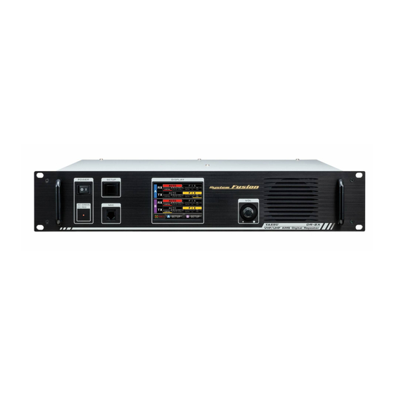
Yaesu DR-2X Operating Manual
Vhf/uhf c4fm/fm
50 ams digital repeater
Hide thumbs
Also See for DR-2X:
- Installation instructions manual (9 pages) ,
- Operating manual (56 pages) ,
- Setup (13 pages)
Table of Contents
Advertisement
Advertisement
Table of Contents

Related Manuals for Yaesu DR-2X


Summary of Contents for Yaesu DR-2X
- Page 1 VHF/UHF C4FM/FM 50W AMS DIGITAL REPEATER Operating Manual...
-
Page 2: Table Of Contents
Company and product names described in this manual are trademarks and registered trademarks of their respective companies. Unauthorized reproduction or copying of a part or all of the copyrights owned by Yaesu Musen Co., Ltd. in any form whatsoever is strictly prohibited. -
Page 3: Introduction
Congratulations on your purchase of the DR-2X/DR-2XE Yaesu 144/430MHz Dual Band Dual Receive C4FM/ FM Digital Repeater. The YAESU DR-2X/DR-2XE is a C4FM digital / analog FM dual mode and dual receive repeater that covers the VHF and UHF amateur radio bands. DR-2X/DR-2XE incorporates the use of Analog FM communication integrated with the C4FM digital communication through its unique AMS capability. - Page 4 Do not place the device on an unsteady or sloping surface, or This may result in injury, electric shock and equipment failure. in a location where there is a lot of vibration. The device may fall over or drop, resulting in fire, injury and equipment failure. DR-2X / DR-2XE Operating Manual...
-
Page 5: Setting Up The Repeater
About electrical grounding The DR-2X/DR-2XE repeater, like any other communications apparatus, requires an effective ground system for maximum electrical safety and best communications effectiveness. A good ground system can contribute to station efficiency in a number of ways: •... -
Page 6: Connecting Antenna Cables
Connecting Antenna Cables The figure above shows the rear panel of the DR-2X. 1 When using a duplexer, plug the coaxial cables from the TX ANT and RX ANT terminals into the jacks of the duplexer, and tighten the connectors. -
Page 7: Connecting The Power Supply
Connecting the Power Supply Connection for DR-2X (US and Asian versions) z Main power Use an AC outlet capable of supplying AC 100-240V at 50 or 60Hz. 1 Insert the socket of the provided AC power cord into the AC IN jack at the rear of the repeater. -
Page 8: Connecting External Devices
Make sure to switch off the power to the radio before connecting the cable. z When using the SCU-20, PC connection cable, a dedicated driver must be installed in the personal computer. Download and use the driver and installation manual from the YAESU website. DR-2X / DR-2XE Operating Manual... -
Page 9: Accessories And Options
Press “ | ” side to switch the repeater ON, and “” side to switch the repeater OFF. LED Indicator • When the indicator illuminates in green, the power is supplied from the AC IN jack (DR-2X only). • When the indicator illuminates in red, the power is supplied from the DC IN terminals (DR-2XE) or BACKUP terminals (DR-2X). -
Page 10: Rear Panel
A 15A fuse for the DC power supply through the BACKUP / DC IN jack is attached. Power Supply BACKUP Jack (DR-2X) / DC IN jack (DR-2XE) Connect to a 13.8V DC power supply with the supplied DC power cord. -
Page 11: Initial Set Up
(LED indicator) will illuminate. z When the power is supplied from the AC IN jack, the indicator illuminates in green (DR-2X only). z When the power is supplied through the BACKUP terminals / DC IN terminal (13.8V DC), the indicator illuminates in red. -
Page 12: Set Up Operation Mode
To reset, touch the area again. Single CH Operation If you do not need the second CH on DR-2X/DR-2XE, just enter any frequency on CH-B and do not connect the uplink antenna to RX ANT B. CH-B can be used exclusively for repeater control without any repeater operation. In this case, the downlink frequency of CH-B is not displayed. -
Page 13: Set Up Frequency
3. Set up Frequency Set up Dual Receive Frequency DR-2X/DR-2XE is equipped with dual receive feature that may receive two different frequencies in the VHF and the UHF Band of Amateur radio bands, so the other uplink and downlink frequency for emergency communications may be set separately from the normally used frequency. -
Page 14: Select Downlink Antenna
4 0 DOWN L I N K TO ANT-A 4 4 0 Since the DR-2X/DR-2XE has only one transmitter, even if the downlink frequency is set separately, the signal will not be transmitted simultaneously. DR-2X / DR-2XE Operating Manual... -
Page 15: Set Up Priority Channel
Priority mode Normal operation mode The uplinks may be received simultaneously, but since the DR-2X/DR-2XE has only one transmitter, even if the downlink frequency is set separately; the signals may not be transmitted simultaneously. In the FIX (Digital C4FM) mode, when CH-A or CH-B is set to Priority, a received C4FM digital signal including the registered DG-ID will have precedence over signals received on the other channel. -
Page 16: Set Up Other Functions
To avoid damage to the test equipment, always connect the signal generator directly to the RX antenna connector on the DR-2X/DR-2XE. z While the squelch level is being set, repeater transmit operation is temporarily permitted. This will facilitate checking the performance of the Duplexer, and allow evaluation of the receiver sensitivity degradation (“desense”), during... -
Page 17: Base Mode Operation
The repeater can be used as a VHF/UHF base station by connecting an optional MH-48A6JA or MH-42C6J microphone to the “MIC” jack on the front panel. z The base mode operation is available only on CH-A. z For Base Station operation, set CH-A to FIX DIGITAL mode. MH-48A6JA or MH-42C6J DR-2X / DR-2XE Operating Manual... -
Page 18: Set Up Dg-Id Number
• The latest firmware for each transceiver is available on the YAESU website. • The DR-2X/DR-2XE will repeat on the downlink, only the uplink signals with the corresponding DG-ID number if the DG-iD number is set to an arbitrary number from “01” to “99”, (other than “00”. and signals with a different DG-ID number will not transmit on the downlink. -
Page 19: Setting The Dg-Id Number
4 Touch [ ▲ ] or [ ▼ ] to select the desired DG-ID number to be registered LOCAL RPT DG-ID to the DR-2X/DR-2XE repeater. DG-ID Down Link OWN When using the DR-2X/DR-2XE as an Open Repeater that anyone may use, set the DG-ID to “00”. Name MY RPT BACK BACK [ Name ] twice. -
Page 20: Default Id Setting
Blue: Default DG-ID (TOT does not work on an uplink signal that includes the same DG-ID) BACK BACK 5 Touch [ ▲ ] or [ ▼ ] to select the desired DG-ID number and register it to the Group. DR-2X / DR-2XE Operating Manual... - Page 21 13 Touch [ ENT ] . The Group name setting is saved and the display will return to Group Caps DG-ID setting screen. 14 Touch [ BACK ] 4 times. The screen returns to the operation mode screen. DR-2X / DR-2XE Operating Manual...
-
Page 22: Dg-Id Tot Setting
5 Touch [ ▲ ] or [ ▼ ] to select TOT time. TX TOT 3 min Selectable from 0/30sec/1min/1.5min/2min/2.5min/3min/4min/5min/1 0min/CONT. IMRS TOT The default setting is 1 min. BACK BACK 6 Touch [ BACK ] 4 times. The screen returns to the operation mode screen. DR-2X / DR-2XE Operating Manual... -
Page 23: Set Up Dp-Id
DG-ID number of the controlling C4FM digital transceiver to the DR-2X/DR-2XE. When receiving the uplink signal containing the DP-ID that is registered to the DR-2X/DR-2XE, the signal is received and transmitted on the downlink preferentially. In addition, if connecting multiple repeaters via the Internet, signals containing the registered DP-ID will be transmitted on the multiple repeater downlinks (the local repeater signals may also be transmitted on the downlink.). - Page 24 • Sets the repeater function ON or OFF (only the locally connected repeater, or all the linked repeaters) • Changing Downlink Transmission Power • Recording / Playing / Clearing the Voice Message • Setting of the Emergency Call DR-2X / DR-2XE Operating Manual...
-
Page 25: Basic Set Up And Operations
CH-A is “AUTO AMS”. When communicating only with group members, only the C4FM digital transceiver may be received by changing the operation mode of CH-A to FIX DIGITAL, so only the group members with the same DG-ID may communicate. DR-2X / DR-2XE Operating Manual... -
Page 26: Advanced Set Up And Operations
10. [ Example ] Advanced Set up and Operations IMRS (Internet-linked Multi-site Repeater System) The repeater, installed the optional LAN Unit LAN-01A and connected the multiple DR-2X/DR-2XE repeaters via the Internet, may be accessed as stand-alone or as a group repeater (Up to 99 units). - Page 27 Transceiver beeps 3 times to notify that the accessed repeater failed to activate the downlink of the accessed repeaters. z Register all the DG-IDs used in the group for each DR-2X/DR-2XE. In the RPT Group, DG-ID registration screen of RPT-A, register all the DG-ID numbers 01,02, 03, 04, 10, 20, 50 used within the group members.
-
Page 28: Remote Controls
• Remote operation sends commands on the uplink frequency of CH-B. • When remote control is required, it is necessary to set whether to control the DR-2X/DR-2XE with analog FM or C4FM in advance. Selection of analog FM, C4FM digital Touch [ A SETUP ] or [ B SETUP ] on the operation mode screen. -
Page 29: C4Fm Digital Control
• Remote control with C4FM digital can be done only when the transceiver DP-ID has been registered to the DR-2X/DR-2XE in advance. Remote operation cannot be performed with a transceiver when the DP-ID has not been registered, so you can securely manage repeaters. -
Page 30: Change The Remote Command
8 Enter a 4-digit control code. ACTIVATE *1111 The screen returns to the command list. The same code as another function may not be set. Touch [ BACK ] 4 times. Space The screen returns to the operation mode screen. DR-2X / DR-2XE Operating Manual... -
Page 31: Actual Remote Control Procedure
When controlling remotely with the FTM-400D 1 Please confirm that the FTM-400D DP-ID is registered on the DR-2X/DR-2XE repeater. 2 Tune the transmit frequency of the FTM-400D to the uplink frequency of the CH-B side of the DR-2X/DR- 2XE. 3 Set the FTM-400D to the digital mode, then press and hold the “” key on the microphone (MH-48A6JA). -
Page 32: Voice Messages
In order to record a message, first register the transceiver DP-ID on the DR-2X/DR-2XE repeater. 1 Tune the transmit frequency to the uplink frequency of the CH-B side of the DR-2X/DR-2XE. 2 Set the transceiver to the C4FM digital mode, then press and hold the “” key on the microphone. -
Page 33: Setting The Interval And Number Of Voice Messages
14. Setting the interval and number of voice messages The DR-2X/DR-2XE has a message function that automatically transmits the recorded message on the downlink frequency at specified intervals and number of times. Setting the transmission interval of the message: 1 Touch [ A SETUP ] or [ B SETUP ] to display the frequency set up screen, then touch [ F ] on the bottom of the screen. -
Page 34: Operate Message Function At The Dr-2X/Dr-2Xe Site
To Record a message for Analog FM: 1 Connect an optional MH-48A6JA or MH-42C6J microphone to the “MIC” jack on the front panel of the DR-2X/DR-2XE. 2 Touch [ A SETUP ] or [ B SETUP ] on the bottom of the Operation Mode Screen, then touch [ F ] . - Page 35 C L E A R M E S S A G E F I X D I G I T A L * 3 3 3 3 A U T O * 4 4 4 4 P L A Y DR-2X / DR-2XE Operating Manual...
-
Page 36: Set Up Various Functions
4 RX100.0Hz TX100.0Hz 5 Touch [ ▲ ] or [ ▼ ] , or touch the item repeatedly. The set value will change each time it is touched. 8 4 RX123.0Hz TX100.0Hz DR-2X / DR-2XE Operating Manual... -
Page 37: Setting The Half Deviation Operation
Factory default: 023 z DCS codes between 023 and 754 can be selected. z Each TX and RX can be set to different code. z This setting item may be set on the CH-A and CH-B individually. DR-2X / DR-2XE Operating Manual... -
Page 38: Set The Tone Signal Type For Analog Fm Mode
When operating in the USA the CW ID SPEED setting time must not exceed 20 words per minute when keyed by an automatic device, to comply with the FCC rule Part 97: Sec. 97.119 (b)(1) Station identification. DR-2X / DR-2XE Operating Manual... -
Page 39: Setting The Sql Hysteresis
4 Touch [ BACK ] 4 times. The setting is determined and the display will return to the operation mode screen. z Factory default: 0ms z This setting item is common to CH-A and CH-B. DR-2X / DR-2XE Operating Manual... -
Page 40: Setting The Display Turn-Off Time
Enter the previously registered 4-digit password (default “0000”). z To reset the DR-2X/DR-2XE, press and hold in the [ SETUP ] button while turning the transceiver ON à the password input screen will appear à press and hold the [ SETUP ] button for 2 seconds à the reset confirmation screen will appear à... -
Page 41: Restoring Default Settings (Factory Reset)
17. Restoring Default Settings (Factory Reset) 1 Turn the DR-2X/DR-2XE OFF. POWER SETUP 2 Press and hold in the [ SETUP ] button while turning the transceiver Continue pressing the [ SETUP ] button until the operation mode screen appears on the display. -
Page 42: Connect To The Hri-200 Node Station
18. Connect to the HRI-200 node station To use WIRES-X with DR-2X/DR-2XE, connect HRI-200 directly to the 10-pin plug on the back of the DR-2X/ DR-2XE. Alternatively, there is a method the HRI-200 Node station may be located in a place different from the repeater site. - Page 43 While pressing and holding the [ SETUP ] button, press the [ POWER ] switch. POWER SETUP While the “YAESU” logo is being displayed, release the [ SETUP ] button. “HRI+REPEATER MODE” will appear on the display. Touch [ OK? ].
-
Page 44: Remote Operation With External Controller
You can transmit by the microphone and PTT input of the front panel in all settings except AMS/AMS. Control from external controller To control the DR-2X/DR-2XE remotely, optional cables can be used to connect the repeater to an external controller. - Page 45 This pin provides 13.8V, 2.0A, DC from the repeater supply. There is an internal 3 A fuse to prevent damage to the repeater. These functions may only be activated while the repeater is in Remote mode. ø DR-2X / DR-2XE Operating Manual...
- Page 46 Analog Analog audio output Even when using the DR-2X/DR-2XE with an external controller, the COR, analog and digital IDs, TOT, DCS/CTCSS, TX power, etc. are already controlled by the DR-2X/DR-2XE internal control. These internal controls cannot be disabled. The external controller must not conflict with these functions. Some functions of the internal controller cannot be overridden.
- Page 47 Setting to connect the repeater controller S-COM7330 Set up instructions to interface the Triple Repeater Controller S-COM7330 with the DR-2X/DR-2XE. Modification of S-COM7330 1 Remove the 6 screws from each side and 2 screws from the top cover of the S-COM7330, then remove the top cover.
- Page 48 Connecting S-COM7330 S-COM7330 PORT 3 PORT 2 PORT 1 RS232-2 RS232-1 INIT RESET DC 9V-36V This connection needs programming of S-COM7330. Repeater 1 Repeater 2 Repeater 3 DR-2X / DR-2XE Operating Manual...
-
Page 49: Specifications
: AC 100-240V (DR-2X only) DC 11.7 to 15.8 V, negative grounding Current consumption : AC: 2 A (max) (@ 117 V Input) (DR-2X only) DC: 1.5 A (receive) 10 A (50 W TX, 144 MHz / 430 MHz band) Operating temperature : DR-2X: −4°F to +140°F (−20°C to +60°C) -
Page 50: After-Market Services
Contact Yaesu Service Center for non-warranty repairs Repairs will be made at the user’s expense if normal functions can be maintained after the repair. Please check with the retail store or Yaesu service center for more information. Arrow Mark side up... - Page 51 EU Declaration of Conformity We, Yaesu Musen Co. Ltd of Tokyo, Japan, hereby declare that this radio equipment DR-2XE is in full compliance with EU Radio Equipment Directive 2014/53/EU. The full text of the Declaration of Conformity for this product is available to view at http://www.yaesu.com/jp/red...
- Page 52 Copyright 2017 YAESU MUSEN CO., LTD. All rights reserved. No portion of this manual may be reproduced without the permission of YAESU MUSEN CO., LTD. YAESU MUSEN CO., LTD. Tennozu Parkside Building 2-5-8 Higashi-Shinagawa, Shinagawa-ku, Tokyo 140-0002 Japan YAESU USA 1708H-AS-1 6125 Phyllis Drive, Cypress, CA 90630, U.S.A.
Need help?
Do you have a question about the DR-2X and is the answer not in the manual?
Questions and answers