Sign In
Upload
Download
Table of Contents
Contents
Add to my manuals
Delete from my manuals
Share
URL of this page:
HTML Link:
Bookmark this page
Add
Manual will be automatically added to "My Manuals"
Print this page
×
Bookmark added
×
Added to my manuals
Manuals
Brands
Yaesu Manuals
Repeater
DR-1X FR
Operating manual
Yaesu DR-1X FR Operating Manual
Vhf/uhf c4fm/fm 50w ams digital repeater
Hide thumbs
1
Table Of Contents
2
3
4
5
6
7
8
9
10
11
12
13
14
15
16
17
18
19
20
21
22
23
24
25
26
27
28
29
30
31
32
33
34
35
36
37
38
39
40
41
42
43
44
page
of
44
Go
/
44
Contents
Table of Contents
Bookmarks
Table of Contents
About this Manual
Table of Contents
Introduction
Features of this Repeater
About the Touch Panel
Safety Precautions (Make Sure to Read These)
Setting up the Repeater
Safety Measures for Installation
Installing the Repeater
About Electrical Grounding
Connecting Antenna Cables
Connecting the Power Supply
Connecting External Devices
Accessories and Options
Supplied Accessories
Optional Accessories
Name and Function of each Component
Front Panel
Rear Panel
1 Initial Set up
Turn the Power on
Set up the ID (Call Sign)
2 Set up Operation Mode
3 Set up Frequency
4 Set up Other Functions
Adjusting the Squelch Level
Adjusting the Transmit Power
Adjusting the Volume
Turning the Display on and off
5 Base Mode Operation
6 Set up DG-ID Number
Digital Group Identification (DG-ID)
Setting the DG-ID Number
7 Set up DP-ID
Digital Personal Identification (DP-ID)
Registering the DP-ID
Delete the Registered DP-ID
8 Remote Controls
Setting the Remote Control
C4Fm Digital Control
ECS (for Analog FM Mode)
Change the Remote Command
9 Actual Remote Control Procedure
Remote Control for C4FM Digital
Remote Control for Analog FM
10 Set up Various Functions
Setting the Tone Signals for Analog FM Mode
Setting the TOT (Time out Timer)
Setting the SQL HYSTERESIS
Setting the SQL TAIL LENGTH
Set the ID Announcement for Analog FM Mode
Set the Tone Signal Type for Analog FM Mode
Setting the Display Turn-Off Time
Password
Setting the Half Deviation Operation
11 Restoring Default Settings (Factory Reset)
12 Connect to the HRI-200 Node Station
13 Remote Operation with External Controller
Turning Remote Operation ON/OFF
Control from External Controller
Setting to Connect the Repeater Controller S-COM7330
Connection with S-COM7330 and DR-1X
Connecting S-COM7330
14 Installation of the Optional Accessories
Installing the Optional Voice Guide Unit FVS-2
15 Specifications
16 After-Market Services
Yaesu Limited Warranty
Advertisement
Quick Links
1
Restoring Default Settings (Factory Reset)
Download this manual
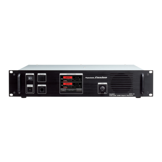
VHF/UHF C4FM/FM
50W AMS DIGITAL REPEATER
DR-1X FR
DR-1XE FR
Operating Manual
Table of
Contents
Previous
Page
Next
Page
1
2
3
4
5
Advertisement
Table of Contents
Need help?
Do you have a question about the DR-1X FR and is the answer not in the manual?
Ask a question
Questions and answers
Related Manuals for Yaesu DR-1X FR
Repeater Yaesu DR-1 Operating Manual
144/430mhz 50w vhf/uhf ams digital repeater (39 pages)
Repeater Yaesu DR-1 Operation Manual
Repeater, base and remote mode (2 pages)
Repeater Yaesu DR-1X Operating Manual
144/430mhz 50w vhf/uhf ams digital repeater. c4fm fdma/fm (48 pages)
Repeater Yaesu DR-1X Technical Supplement
Vhf/uhf ams digital repeater (113 pages)
Repeater Yaesu DR-1X Additional Sheet
(2 pages)
Repeater Yaesu DR-1X Installation Instructions Manual
(10 pages)
Repeater Yaesu DR-1X Operating Manual
System fusion 144/430mhz 50w vhf/uhf ams digital repeater c4fm fdma/fm (44 pages)
Repeater Yaesu DR-1XE Operating Manual
144/430mhz 50w vhf/uhf ams digital repeater (48 pages)
Repeater Yaesu DR-2X Operating Manual
Vhf/uhf c4fm/fm 50 ams digital repeater (52 pages)
Repeater Yaesu DR-2X Installation Instructions Manual
Rx-unit and dsp firmware (9 pages)
Repeater Yaesu DR2XLAN Operating Manual
Vhf/uhf c4fm/fm 50w ams digital repeater (56 pages)
Repeater Yaesu DR-2X Setup
(13 pages)
Repeater Yaesu DR-1XE FR Operating Manual
Vhf/uhf c4fm/fm 50w ams digital repeater (44 pages)
Repeater Yaesu FTR-710A Instruction Manual
Fm repeater 50w pa (154 pages)
Repeater Yaesu HRI-200 Reference Manual
(11 pages)
Repeater Yaesu WIRES-X HRI-200 Instruction Manual
Wide coverage internet repeater enhancement system wires-x connection kit hri-200 (107 pages)
This manual is also suitable for:
Dr-1xe fr
Table of Contents
Print
Rename the bookmark
Delete bookmark?
Delete from my manuals?
Login
Sign In
OR
Sign in with Facebook
Sign in with Google
Upload manual
Upload from disk
Upload from URL


Need help?
Do you have a question about the DR-1X FR and is the answer not in the manual?
Questions and answers